Marantz DV3100 Service Manual
Hide thumbs
Also See for DV3100:
- User manual (41 pages) ,
- Specifications (1 page) ,
- User manual (40 pages)
Table of Contents
Advertisement
Service
Manual
SECTION
1. TECHNICAL SPECIFICATIONS ................................................................................................................ 1
2. PRODUCT SAFETY SERVICING GUIDELINE FOR VIDEO PRODUCTS ................................................ 2
/SERVICING PRECAUTIONS .................................................................................................................... 3
3. INFORMATIONS ........................................................................................................................................ 4
4. SERVICING HINT ....................................................................................................................................... 5
5. REGIONAL CODES ................................................................................................................................... 6
6. LOCATION OF CUSTOMER CONTROLS ................................................................................................. 7
7. DISASSEMBLY ....................................................................................................................................... 2-2
8. EXPLODED VIEWS/PARTS LIST ........................................................................................................... 2-4
9. ELECTRICAL TROUBLESHOOTING GUIDE ......................................................................................... 3-2
10. BLOCK DIAGRAMS .............................................................................................................................. 3-12
11. CIRCUIT DIAGRAMS ............................................................................................................................ 3-18
12. PRINTED CIRCUIT DIAGRAMS/ELECTRICAL PARTS LIST .............................................................. 3-38
13. DECK MECHANISM ................................................................................................................................ 4-1
Please use this service manual with referring to the user guide (D.F.U) without fail.
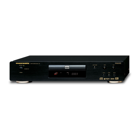
DVD PLAYER DV3100
STANDBY
STANDBY/ON
POWER
TABLE OF CONTENTS
DV3100
DV3100 /
DVD Player
OPEN/CLOSE
STOP
PLAY
PAUSE
N1B
PAGE
R
304W855020 ACT
3120 785 22450
First Issue:2000.10
Advertisement
Chapters
Table of Contents

Related Manuals for Marantz DV3100


Summary of Contents for Marantz DV3100
-
Page 1: Table Of Contents
Service DV3100 / Manual DVD Player DVD PLAYER DV3100 OPEN/CLOSE STOP PLAY STANDBY STANDBY/ON POWER PAUSE TABLE OF CONTENTS SECTION PAGE 1. TECHNICAL SPECIFICATIONS ........................ 1 2. PRODUCT SAFETY SERVICING GUIDELINE FOR VIDEO PRODUCTS ..........2 /SERVICING PRECAUTIONS ........................3 3. - Page 2 MARANTZ Parts for your equipment are generally available to our National Marantz Subsidiary or Agent. ORDERING PARTS : Parts can be ordered either by mail or by Fax.. In both cases, the correct part number has to be specified.
-
Page 3: Technical Specifications
TECHNICAL SPECIFICATIONS DVD VIDEO PLAYER Power supply AC 120V, 60Hz(U1B) /AC100V, 50/60Hz(F1N) /AC220~240V, 50Hz(N1B) /110~240V, 50Hz(K1G, A1B) Power consumption Mass 3.2kg(7.1lbs) External dimensions 430 x 88 x 215 (W x H x D) Signal system NTSC 525/60, PAL 625/50 Laser Semiconductor laser, wavelength 650nm Frequency range (audio) 4Hz to 20 kHz... -
Page 4: Product Safety Servicing Guideline For Video Products
PRODUCT SAFETY SERVICING GUIDELINES FOR VIDEO PRODUCTS CAUTION : DO NOT ATTEMPT TO MODIFY THIS PRODUCT IN ANY WAY, SUBJECT : X-RADIATION NEVER PERFORM CUSTOMIZED INSTALLATIONS WITHOUT MANUFAC- 1. BE SURE PROCEDURES AND INSTRUCTIONS TO ALL SERVICE PER- TURER’S APPROVAL. UNAUTHORIZED MODIFICATIONS WILL NOT ONLY SONNEL COVER THE SUBJECT OF X-RADIATION. -
Page 5: Servicing Precautions
SERVICING PRECAUTIONS CAUTION : Before servicing the DVD covered by this service Electrostatically Sensitive (ES) Devices data and its supplements and ADDENDUMS, read and follow Some semiconductor (solid state) devices can be damaged the SAFETY PRECAUTIONS. NOTE : if unforeseen circum- easily by static electricity. -
Page 6: Informations
Some discs have restriction levels that allow you to cut scenes THE DISCS THAT THE DV3100 CAN HANDLE or prevent playback of discs that have contents that you do The following discs can be played back with a DV3100. not want children to watch. disc... -
Page 7: Servicing Hint
4. SERVICING HINT SERVICE HINTS SERVICE TOOLS Audio signals disc 4822 397 30184 Disc without errors (SBC444)+ Disc with DO errors, black spots and fingerprints (SBC444A) 4822 397 30245 Disc (65 min 1kHz) without no pause 4822 397 30155 Max. diameter disc (58.0 mm) 4822 397 60141 Torx screwdrivers Set (straight) -
Page 8: Regional Codes
REGIONAL CODES What are "regional codes"? Motion picture studios want to control the home release of movies in different countries because theater releases arenít simultaneous (a movie may come out on DVD in the US when itís just hitting screens in Europe). Therefore they have required that the DVD standard include codes which can be used to lock out the playback of certain discs in certain geo- graphical regions. -
Page 9: Location Of Customer Controls
LOCATION OF CUSTOMER CONTROLS F R O N T PA N E L DISC TRAY PLAY BUTTON PAUSE BUTTON POWER INDICATOR STOP BUTTON OPEN/CLOSE BUTTON DVD PLAYER DV3100 OPEN/CLOSE STOP PLAY STANDBY STANDBY/ON POWER PAUSE DISPLAY WINDOW POWER BUTTON REMOTE SENSOR... - Page 10 R E M O T E C O N T R O L OPEN/CLOSE button POWER button REPEAT button A-B button POWER OPEN/CLOSE SETUP button RANDOM button SETUP REPEAT RANDOM SUBTITLE button ANGLE button AUDIO SUBTITLE ANGLE SURR. SURR. button AUDIO button TOP MENU MENU...
- Page 11 SECTION 2 CABINET & MAIN CHASSIS CONTENTS 1. DISASSEMBLY .........................2-2 CABINET DISASSEMBLY ......................2-2 CIRCUIT BOARD DISASSEMBLY ....................2-3 2. EXPLODED VIEWS .........................2-4 1. Cabinet and Main Frame Section ...................2-4 2. Packing Accessory Section ....................2-5...
-
Page 12: Disassembly
DISASSEMBLY CAUTION BEFORE STARTING SERVICING Electronic parts are susceptible to static electricity and may easily damaged, so do not forget to take a proper grounding treatment as required. Many screws are used inside the unit. To prevent missing, dropping, etc. of the screws, always use a magnetized screw driver in servicing. -
Page 13: Circuit Board Disassembly
CIRCUIT BOARD DISASSEMBLY Note: Before removing the main circuit board, be sure to shortcircuit the laserdiode output land. After replacing the main circuit board, open the land after inserting the flexible connector. (Refer to Mechanism Disassembly) 1. Disassembling of Main Circuit Board and Interface Board 2. -
Page 14: Exploded Views/Parts List
EXPLODED VIEWS 1. Cabinet and Main Frame Section Scart Jack... -
Page 15: Packing Accessory Section
2.Packing Accessory Section VIDEO AUDIO BATTERY REMOTE CONTROLLER OWNER'S MANUAL PACKING SHEET PACKING PACKING BOX CARTON POS. VERS. PART NO. DESCRIPTON PART NO. POS. VERS. PART NO. DESCRIPTON PART NO. COLOR (ANAM) COLOR (ANAM) (MJI) (MJI) TOP COVER (BLACK) /N1B 9965 000 06954 USER GUIDE (/N1B) 304W851310 /N1B... - Page 16 SECTION 3 ELECTRICAL CONTENTS ELECTRICAL TROUBLESHOOTING GUIDE ..............3-2 1. Power(SMPS) Circuit.......................3-2 2. µ-com Circuit ...........................3-3 3. MPEG Circuit ...........................3-6 4. Front Circuit(Digitron & Key) ....................3-7 5. RF/Servo Circuit ........................3-8 BLOCK DIAGRAMS ........................3-12 1. Overall Block Diagram ......................3-12 2. Power (SMPS) Block Diagram....................3-13 3.
-
Page 17: Electrical Troubleshooting Guide
ELECTRICAL TROUBLESHOOTING GUIDE 1. Power(SMPS) Circuit No 5V_D No VF+ or 5V_A . Is 5.2VA section working? Is 5.2VA section working? Is oscillation present at the Is oscillation present at the anode of D109? Base of Q108? No 5.2VA. Replace D109. Replace Q108. -
Page 18: Μ-Com Circuit
2. µ-COM Circuit A. No Power POWER ON Does Bar appear at FLD? Is P5901 Do all five Bars appear? connected normally? Reconnect it. Does Logo appear Check power. on the screen? (Refer to power) If power is normal Is P5901 Pin 24 normal? Refer to Front Part Is oscillation of waveform on A[00:21]... - Page 19 B. Audio abnormal C. Video abnormal AUDIO ABNORMAL VIDEO ABNORMAL Check Audio jack. Check Video jack. YES (If OK) YES (If OK) Check PLL FC of MPEG part. Refer to Video part. YES (If OK) YES (If OK) Refer to Audio part. Refer to Encoder part.
- Page 20 E. Picture abnormal PICTURE ABNORMAL Check the disc. Refer to Servo part If OK Check PLL IC of MPEG part YES (If OK) Check DSP YES (If OK) Check MPEG YES (If OK) Replace B/D F. Disc Error DISC ERROR Check Disc YES (If OK) Refer to Servo part...
-
Page 21: Mpeg Circuit
3. MPEG Circuit Power is on Does LG Logo appear Check power & clock. on the screen? Does the Check CD/DVD DSP output moving picture of the DVD Disc Is MPEG data signal normal? play on the screen signal. normally? Check MPEG Decoder input signal. -
Page 22: Front Circuit(Digitron & Key)
4. Front Circuit (Digitron & key) START Power on. Is oscillation of Check Power. LED ON? X901 normal? Check waveform Is Digitron on normally? Replace IC902. of IC901 Pin 6. Do all the Is waveform of IC901 Check waveform buttons work Pin 76 normal? of IC901 Pin 13. -
Page 23: Rf/Servo Circuit
5. RF/Servo Circuit CHECK POINT(General) Does signal goes "High" to IC201 Pin194 when the power is on? Does signal pulse Check "2.µ-COM Part". input to IC201 Pins 58, 59 when the power is on? Does Does Replace X301 or IC304 TTL pulse output to 33.8688MHz clock input IC201 Pins 140, 142? - Page 24 No disc .Power on Check loading Part. Push Pick-up to inner track to Does tray open or close? the end by hand. Does DECK assembly is defective. PMD03 Pin 7 change (Limit sw) high to low? Pressing the open/close key repeatedly, check the voltage of IC2M1 check µ-COM Part.
- Page 25 DISC IN OPEN/CLOSE Fig.3. FOCUS ERROR waveform Check Check IC2A1 Pin 11,12,13,14 the focus error moving the FOCUS ON? lens up and down. in DVD Mode (IC2A1 Pin 42) IC201 no output : Pick-up is defective. Does the TTL level change at IC201 Replace IC201.
- Page 26 CHECK A Fig.5. RF waveform Check RF Eye-Pattern. No signal: Pick-up is defective Check IC2A1 Pins 5, 6, 7, 8. RF : 1.5-1.6V(IC2A1 Pin 57) Does the sawtooth waveform emit Is the eye-pattern vivid? Does the 1.6V emit? Replace IC2A1. at IC2A1 Pin 41? Replace IC201.
-
Page 27: Block Diagrams
BLOCK DIAGRAMS 1. Overall Block Diagram 3-12... -
Page 28: Power(Smps) Block Diagram
2. Power(SMPS) Block Diagram TRANS SWITCHING TR RECTIFIER LINE FILTER 3-13... -
Page 29: Rf/Cd Dsp/Dvd Dsp/Dvd Servo Block Diagram
3. RF/CD DSP/DVD DSP/DVD SERVO Block Diagram 3-14... -
Page 30: Audio Block Diagram
4. Audio Block Diagram 3-15... -
Page 31: Mpeg Block Diagram
5. MPEG Block Diagram 3-16... -
Page 32: Μ-Com Block Diagram
6. µ-COM Block Diagram 3-17... -
Page 33: Circuit Diagrams
THIS CIRCUIT DIAGRAM MAY OCCASIONALLY DIF- 1. Shaded( ) parts are critical for safety. Replace only CUMSTANCES SHOULD THE ORIGINAL DESIGN BE 1. POWER(SMPS) CIRCUIT DIAGRAM (DV3100/U1B,/F1N) FER FROM THE ACTUAL CIRCUIT USED. THIS WAY, with specified part number. MODIFIED OR ALTERED WITHOUT PERMISSION IMPLEMENTATION OF THE LATEST SAFETY AND 2. - Page 34 WHEN SERVICING THIS CHASSIS, UNDER NO CIR- CATION. 1. Shaded( ) parts are critical for safety. Replace only CUMSTANCES SHOULD THE ORIGINAL DESIGN BE 1. POWER(SMPS) CIRCUIT DIAGRAM (DV3100/A1B,/N1B) THIS CIRCUIT DIAGRAM MAY OCCASIONALLY DIF- with specified part number. MODIFIED OR ALTERED WITHOUT PERMISSION FER FROM THE ACTUAL CIRCUIT USED.
-
Page 35: Dvd Dsp Circuit Diagram
2. DVD DSP CIRCUIT DIAGRAM IC203 is defective. AD Converter Error - No tracking/Focus control IC204 is defective. Scratched CD Audio abnormal. '00. 04. 17 R10536A MARANTZ TRACKING LOOP SLED LOOP WAVEFORM FOCUS LOOP SPINDLE LOOP 3-22 3-23... -
Page 36: Drive & Rf Circuit Diagram
IC2A2 is defective. Q2M3 is defective. Q2A1, Q2A2 are defective. '00. 04. 17. R10535A No fucus & tracking control. Spindle rotates in high speed. CD/DVD LD will not be on. MARANTZ TRACKING LOOP SLED LOOP WAVEFORM FOCUS LOOP SPINDLE LOOP 3-24... -
Page 37: Mpeg Circuit Diagram
IC306 is defective. CVBS/Y/C out bad. IC307 is defective. Component out bad. "B" *OPTION Table '00. 04. 17 R10538A IC302, IC303 are defective. C/No DV3100/N1B ect. X301 is defective. MARANTZ Q301, 304 are defective. A/V out bad. R3B1 0 ohm No power on. -
Page 38: Waveforms
• WAVEFORMS (RF/SERVO) (VIDEO ENCODER) Stop : 1 00kS/s 3290 Acqs Record Length Fit to Screen points in 10divs 1000 points in 20divs 2500 points in 50divs more M 500µs 280/mV 1 of 3 1.00V Trigger Record Horiz Time Base Horiz FastFrame Position... -
Page 39: Audio Dm & 5.1Ch Circuit Diagram
Q401 is defective. 2CH Audio out bad. IC401 is defective 2CH Audio out bad IC402 is defective. 2CH Audio out bad. IC403, Q404 are defective. Digital data out bad. '00. 04. 17 R10539A MARANTZ 2CH L SIGNAL 2CH R SIGNAL 3-30 3-31... -
Page 40: Μ-Com/Expander
6. µ-COM/EXPANDER CIRCUIT DIAGRAM DV3100/K1G(ASIA) : IC502(FLASH ROM) 16M DV3100/U1B, F1N, N1B, A1B : IC502(FlASH ROM) 8M Servo will not operate FLASH ROM SDRAM FLD Error MAIN CPU Video output level is unstable CPLD Audio output is unstable Open, Close Error... -
Page 41: Digitron & Key Circuit Diagram
7. DIGITRON(TIMER) & KEY CIRCUIT DIAGRAM Q901, Q902 are defective. DIG901 is defective. LED will not operate. FLD is distorted. FRONT CONTROL IC902 is defective. RESET Reset Error. RC901 is defective. R/C Error. REMOCON RECEIVE MIC OPTION '00. 04. 17 R10540A MARANTZ 3-34 3-35... -
Page 42: Jack Circuit Diagram
8. JACK CIRCUIT DIAGRAM DV3100/N1B, K1G, A1B ONLY /U1B, /A1B, /F1N ONLY SCART OPTION (DV3100/N1B OPTION) 16:9 can’t be changed '00. 04. 17 R10541A MARANTZ OPTICAL S VIDEO (C) COMP.VIDEO AUDIO (L) S VIDEO (Y) AUDIO (R) 3-36 3-37... -
Page 43: Printed Circuit Diagrams
PRINTED CIRCUIT DIAGRAMS 1. MAIN P.C.BOARD LOCATION GUIDE (TOP SIDE) (BOTTOM SIDE) 3-38 3-39... -
Page 44: Power,A/V,Front P.c.board
2. Power, A/V, Front P.C.BOARD LOCATION GUIDE 3-40 3-41... -
Page 45: Key P.c.board
3. KEY P.C.BOARD 4. Power LED P.C.BOARD 3-42... -
Page 46: Electrical Parts List
ELECTRICAL PARTS LIST NOTE ON SAFETY FOR FUSIBLE RESISTOR : ASSIGNMENT OF COMMON PARTS CODES. RESISTORS : 1) GD05 x x x 140, Carbon film fixed resistor, ±5% 1/4W The suppliers and their type numbers of fusible resistors are as : 2) GD05 x x x 160, Carbon film fixed resistor, ±5% 1/6W follows ;... - Page 47 5. ELECTRICAL PARTS LIST POS. VERS. PART NO. DESCRIPTON PART NO. POS. VERS. PART NO. DESCRIPTON PART NO. COLOR (ANAM) (MJI) COLOR (ANAM) (MJI) BC101 /N1B 9965 000 06959 BEAD CORE BFS3550R2FD8 *FC900210R C2B3 /N1B GRM39Y5V473Z25C500 PT266 BD101 4822 130 81248 S1WBA60 (1A 600V) *HD201400R C2B4 560PF 50V K NP0 1608...
- Page 48 POS. VERS. PART NO. DESCRIPTON PART NO. POS. VERS. PART NO. DESCRIPTON PART NO. COLOR (ANAM) (MJI) COLOR (ANAM) (MJI) C408 0.1µF 50V Z Y5V(F) 1508 FH101 FUSE CLIP C409 4822 124 11131 47µF 6.3V M 85STD(CYL) EY47600620 FH102 FUSE CLIP C410 4822 124 11131 47µF 6.3V M 85STD(CYL) EY47600620...
- Page 49 (ANAM) (MJI) COLOR (ANAM) (MJI) 2K Ω 1 / 16 W 1608 5% D PBJIG 9965 000 07006 DV3100 JIG ASSY *DV3100JIG R293 PBP00 PCB ASSY P.LED R294 150 1/16W 5 D. 2K Ω 1 / 16 W 1608 5% D...
- Page 50 POS. VERS. PART NO. DESCRIPTON PART NO. POS. VERS. PART NO. DESCRIPTON PART NO. COLOR (ANAM) (MJI) COLOR (ANAM) (MJI) R350 R535 10K 1/16W 5 D. 100 1/16W 5 D. R355 R555 R356 R557 100 1/16W 5 D. 0 1/16W 5 D. R558 100 1/16W 5 D.
- Page 51 POS. VERS. PART NO. DESCRIPTON PART NO. COLOR (ANAM) (MJI) RC901 9965 000 07015 TSOP2836WE1 TEMIC 19MM 36.7KHZ *HW100470R SW601 /N1B 9965 000 07016 SKQ-23D15-G3-NA LUP FUNG VDE/S *SS000660R SW901 9965 000 07017 THVV502GAA POSTECH NON 12V 5A *SP001000R SW906 SW908 9965 000 07017 THVV502GAA POSTECH NON 12V 5A *SP001000R...
- Page 52 3-49...
-
Page 53: Disassembly
SECTION 4 MECHANISM CONTENTS 5. Frame Assembly Up/Down ....4-4 DECK MECHANISM PARTS 6. Belt Loading........4-4 LOCATIONS 7. Gear Pulley........4-4 • Top View..........4-1 8. Gear Loading ........4-4 • Top View(without Tray) ......4-1 9. Guide Up/Down.........4-4 • Bottom View ...........4-1 10. PWB Assembly Loading ....4-4 DECK MECHANISM 11. -
Page 54: Deck Mechanism Parts Locations
DECK MECHANISM PARTS LOCATION • Top View (With Tray) Procedure Disass Fig- Parts Fixing Type embly Starting No. Holder 2 Screws, Clamp 2 Locking Tabs Clamp Assembly Disc 1, 2 Plate Clamp 1, 2, 3 Magnet Clamp 1, 2, 3, 4 Clamp Upper Tray Disc 1, 6... -
Page 55: Deck Mechanism Disassembly
DECK MECHANISM DISASSEMBLY HOLDER CLAMP PLATE CLAMP CLAMP ASSEMBLY DISC TRAY DISC MAGNET CLAMP CLAMP UPPER (S1) (S1) HOLDER CLAMP BASE MAIN (Fig. A) EMERGENCY EJECT HOLE (L1) BASE MAIN HOLDER CLAMP LEVER (L1) BASE MAIN BOTTOM SIDE VIEW Fig. 4-1 Fig. -
Page 56: Base Assembly Sled
DECK MECHANISM DISASSEMBLY (L2) GEAR ASSEMBLY FEED GEAR MIDDLE (S2) GEAR ASSEMBLY RACK (S2) (S3) (S2) PICK UP ASSEMBLY GENERAL BASE PU(OUTSERT) (C1) (S2) RUBBER REAR PICK UP ASSEMBLY GENERAL GEAR ASSEMBLY FEED GEAR MIDDLE MOTOR ASSEMBLY SPINDLE GAER ASSEMBLY RACK MOTOR ASSEMBLY SPINDLE Fig. -
Page 57: Frame Assembly Up/Down
DECK MECHANISM DISASSEMBLY GUIDE UP/DOWN GEAR LOADING (L3) (L6) GEAR PULLEY (L6) (L4) BASE MAIN BELT LOADING (H1) PWB ASSEMBLY LOADING (L6) (C2) (S5) BASE MAIN FRAME ASSEMBLY UP/DOWN (S4) (L5) FIG. (A) GUIDE UP/DOWN FIG. (B) GUIDE UP/DOWN GUIDE UP/DOWN FIG. -
Page 58: Deck Mechanism Adjustment
DECK MECHANISM ADJUSTMENT 1. Tools and Fixtures for SVC • For SVC Program Down-Load Not spare parts Included in <Jig board> PART NO.*DV3100JIG Fig.2. FFC Cable (15 pin) Fig.3. Jig Board Fig.4. Deviation Disc (0.8mm) Fig.1. Printer Cable • For T-Skew and R-Skew Adjustment Not spare parts Not spare parts Fig.7. - Page 59 DECK MECHANISM ADJUSTMENT M E M O CURRENT PICK UP POSITION ERROR RATE SIZE SECTOR : 200145 ERROR RATE (HEXADEAMAL) 0045 0065 AVERAGE ERROR RATE Fig.11. Adjusting Screen Display 3. Adjustment Procedure R-SKEW ADJUSTING HOLE 1. Insert Disc(Only Open/Close Key Pressing) T-SKEW ADJUSTING HOLE 2.
-
Page 60: Exploded View
EXPLODED VIEWS 1. Deck Mechanism Exploded View POS. VERS. PART NO. DESCRIPTON PART NO. COLOR (PCS) (MJI) DECK ASSY DVD PLAYER(DP2) 304W304500 9965 000 06956 CLAMP ASSY DISC(DP2) 304W005500 BASE ASSY MAIN(DP2 PLAYER) 304W064500 9965 000 06957 BASE ASSY SLED(DP2) 304W304510 BASE ASSY FRONT (ADVD3520NC 1UM1)