Table of Contents
Advertisement
Quick Links
RX-V661/HTR-6060/DSP-AX761
This manual has been provided for the use of authorized YAMAHA Retailers and their service personnel.
It has been assumed that basic service procedures inherent to the industry, and more specifically YAMAHA Products, are already
known and understood by the users, and have therefore not been restated.
WARNING:
IMPORTANT:
The data provided is believed to be accurate and applicable to the unit(s) indicated on the cover. The research, engineering, and
service departments of YAMAHA are continually striving to improve YAMAHA products. Modifications are, therefore, inevitable
and specifications are subject to change without notice or obligation to retrofit. Should any discrepancy appear to exist, please
contact the distributor's Service Division.
WARNING:
IMPORTANT:
I CONTENTS
To Service Personnel .......................................... 2
Front Panels ........................................................ 3–4
Rear Panels .......................................................... 5–8
Remote Control Panels ...................................... 9
Internal View ......................................................... 13
..................................... 18–25
1 0 1 0 4 2
AV RECEIVER/AV AMPLIFIER
Failure to follow appropriate service and safety procedures when servicing this product may result in personal
injury, destruction of expensive components, and failure of the product to perform as specified. For these reasons,
we advise all YAMAHA product owners that any service required should be performed by an authorized
YAMAHA Retailer or the appointed service representative.
The presentation or sale of this manual to any individual or firm does not constitute authorization, certification or
recognition of any applicable technical capabilities, or establish a principle-agent relationship of any form.
Static discharges can destroy expensive components. Discharge any static electricity your body may have
accumulated by grounding yourself to the ground buss in the unit (heavy gauge black wires connect to this buss).
Turn the unit OFF during disassembly and part replacement. Recheck all work before you apply power to the unit.
................................ 10–12
.......... 14–17
26–52
2007
This manual is copyrighted by YAMAHA and may not be copied or
redistributed either in print or electronically without permission.
SERVICE MANUAL
IMPORTANT NOTICE
Display Data ..................................................... 54–55
Ic Data ................................................................. 56–70
Block Diagrams .............................................. 71–75
Printed Circuit Boards ................................ 76–88
Pin Connection Diagrams ............................ 89–91
Schematic Diagrams .................................... 93–101
Replacement Parts List .......................... 103–129
Remote Control .......................................... 130–133
Scene Control ..................................................... 137
All rights reserved.
53
.... 134–136
P.O.Box 1, Hamamatsu, Japan
'07.03
Advertisement
Table of Contents

Related Manuals for Yamaha RX-V661


Summary of Contents for Yamaha RX-V661
-
Page 1: Service Manual
This manual has been provided for the use of authorized YAMAHA Retailers and their service personnel. It has been assumed that basic service procedures inherent to the industry, and more specifically YAMAHA Products, are already known and understood by the users, and have therefore not been restated. - Page 2 RX-V661/HTR-6060/DSP-AX761 I TO SERVICE PERSONNEL AC LEAKAGE WALL EQUIPMENT TESTER OR 1. Critical Components Information OUTLET UNDER TEST EQUIVALENT Components having special characteristics are marked s and must be replaced with parts having specifications equal to those originally installed. 2. Leakage Current Measurement (For 120V Models Only)
-
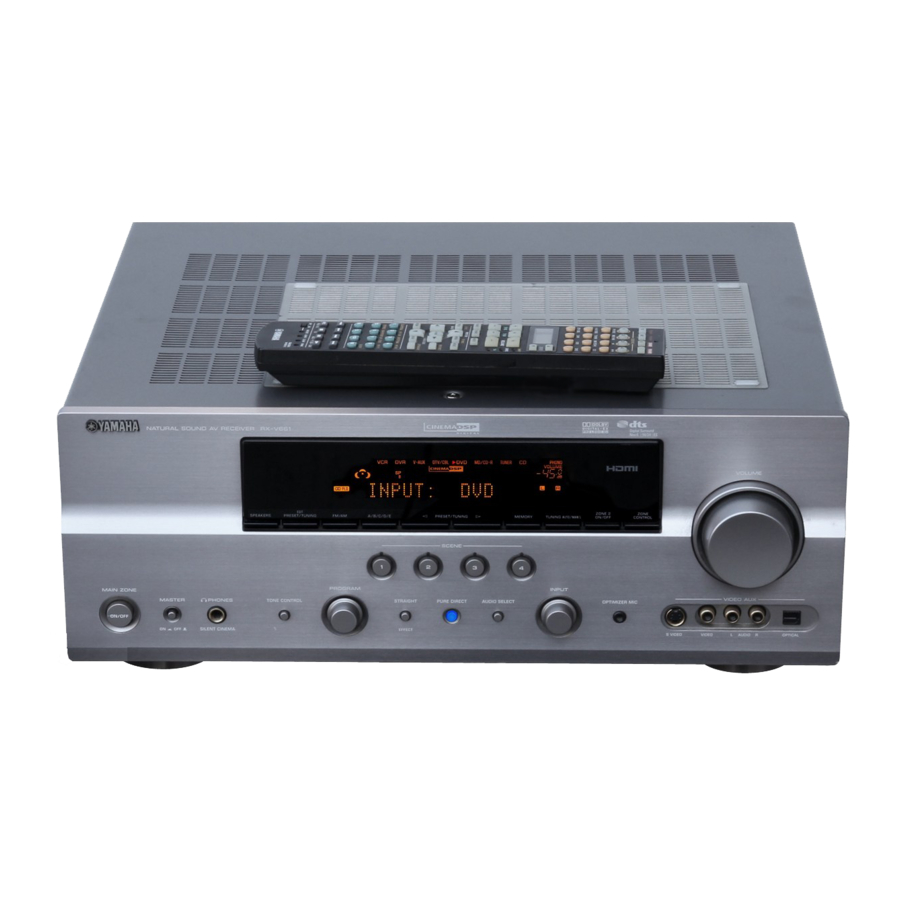
Page 3: Front Panels
RX-V661/HTR-6060/DSP-AX761 I FRONT PANELS RX-V661 (U, C models) RX-V661 (R, T, K, A, G, E, L models) HTR-6060 (U, C models) - Page 4 RX-V661/HTR-6060/DSP-AX761 HTR-6060 (G model) DSP-AX761 (B model) DSP-AX761 (J model)
-
Page 5: Rear Panels
RX-V661/HTR-6060/DSP-AX761 I REAR PANELS RX-V661 (U, C models) RX-V661 (R model) RX-V661 (T model) - Page 6 RX-V661/HTR-6060/DSP-AX761 RX-V661 (K model) RX-V661 (A model) RX-V661 (G, E models)
- Page 7 RX-V661/HTR-6060/DSP-AX761 RX-V661 (L model) HTR-6060 (U, C models) HTR-6060 (G model)
- Page 8 RX-V661/HTR-6060/DSP-AX761 DSP-AX761 (B model) DSP-AX761 (J model)
-
Page 9: Remote Control Panels
RX-V661/HTR-6060/DSP-AX761 I REMOTE CONTROL PANELS • RAV326 • RAV327 • RAV364 RX-V661 (U, C models) RX-V661 (R, T, A, L models) RX-V661 (K, G, E models) HTR-6060 (U, C models) DSP-AX761 (J model) HTR-6060 (G model) DSP-AX761 (B model) -
Page 10: Specifications
(IHF, 1 kHz, 100 % MOD.) Mono ..............2.8 µV (20.2 dBf) ................1.0 V / 1.2 k-ohms [RX-V661 (U, C, R, T, K, A, G, E, L models)/HTR-6060 (G model)] Signal to Noise Ratio / (IHF) ZONE2 OUT ..........200 mV / 1.2 k-ohms Mono / Stereo ............. - Page 11 (U, C models) MUSIC ENHANCER 7ch Stereo – – Maximum Power Consumption / (6ch drive, 10 % THD) “SILENT CINEMA” is a trademark of YAMAHA CORPORATION. iPod Listening DIGITAL AUDIO PLAYER iPod DOCK (V-AUX) MUSIC ENHANCER 7ch Stereo R model .................. 800 W...
- Page 12 RX-V661/HTR-6060/DSP-AX761...
-
Page 13: Internal View
DSP P.C.B. Tuner (U, C, R, T, K, A, G, E, L, J models) OPERATION (2) P.C.B. OPERATION (5) P.C.B. (RX-V661: U, C, R, T, K, A, G, E, L models / HTR-6060: G model) OPERATION (3) P.C.B. OPERATION (1) P.C.B. -
Page 14: Disassembly Procedures
RX-V661/HTR-6060/DSP-AX761 I DISASSEMBLY PROCEDURES (Remove parts in the order as numbered.) Disconnect the power cable from the AC outlet. 1. Removal of Top Cover a. Remove 4 screws (1), 5 screws (2) and screw (3). (Fig. 1) b. Slide the top cover rearward to remove it. (Fig. 1) 2. - Page 15 B. (Fig. 2) FUNCTION (5) P.C.B. b. Remove 2 push rivets (9). (Fig. 2) c. Remove 10 screws (RX-V661: U, C, R, T, K, A, G, E, L CB43 models, HTR-6060: G model, DSP-AX761: B model) / 9 screws (HTR-6060: U, C models) (0). (Fig. 4) CB47 d.
- Page 16 RX-V661/HTR-6060/DSP-AX761 6. Removal of HDMI P.C.B. When checking the P.C.B.: • Put the rubber sheet and cloth over the equipment. a. Remove screw (D). (Fig. 3) Then place the P.C.B.s upside down on the cloth and b. Remove 5 screws (E). (Fig. 4) check it.
- Page 17 RX-V661/HTR-6060/DSP-AX761 When checking the P.C.B.: • Put a cloth over the equipment. Put the P.C.B.s to- gether with the heat sink upright on the cloth and check them. (Fig. 7) • Reconnect all cables (connectors) that have been disconnected. •...
-
Page 18: Updating Firmware
RX-V661/HTR-6060/DSP-AX761 I UPDATING FIRMWARE / After replacing the DSP P.C.B. and microprocessor (IC81) on the DSP P.C.B. with the replacement parts, update the firmware according to the following procedure. The TI flash ROM (IC51) on the DSP P.C.B. is not sup- plied as a replacement part. - Page 19 RX-V661/HTR-6060/DSP-AX761 3. Connect the writing port of the main unit to the se- rial port (RS232C) of the PC with RS232C cross cable, RS232C conversion adapter and flexible flat cable as shown below. (Fig. 1) Writing port / Rear panel...
- Page 20 RX-V661/HTR-6060/DSP-AX761 When the “Timeout” error is displayed: Press the [Cancel] button and check the following items again. a. Is the power cable of the main unit connected to the AC outlet? b. Reconnect cables, etc. being used in Step 3 of the operation procedure and start “Flash...
- Page 21 RX-V661/HTR-6060/DSP-AX761 10. Press the [E.P.R...] button, and “Erase OK?” is displayed. (Fig. 4) Press the [OK] button and start writing. (Fig. 4) 11. When writing is completed, “Program Finished” is displayed. (Fig. 4) Press the [OK] button. (Fig. 4) 12. Disconnect the power cable of main unit from the AC outlet.
- Page 22 RX-V661/HTR-6060/DSP-AX761 1. Reconnect the power cable of main unit to the AC outlet. 2. Press the “MASTER ON/OFF” (RX-V661, HTR- 6060: G model) / “STANDBY/ON” (HTR-6060: U, C models, DSP-AX761) key while simultaneously pressing the “STRAIGHT” and “AUDIO SELECT” keys. (Fig. 5) Then the DIAG function is activated.
- Page 23 RX-V661/HTR-6060/DSP-AX761 Writing to DSP 1. Turn off the power of main unit and disconnect the power cable from the AC outlet. 2. Set the switch (SW301) of RS232C conversion adapter to the “OTHER” side. (Fig. 6) 3. Connect the writing port of the main unit to the serial...
- Page 24 [RDY] button Fig. 8 7. Reconnect the power cable of main unit to the AC outlet. 8. Press the “MASTER ON/OFF” (RX-V661, HTR-6060: G model) / “STANDBY/ON” (HTR-6060: U, C models, DSP-AX761) key while simultaneously pressing “STRAIGHT” and “AUDIO SELECT” keys of the main unit.
- Page 25 RX-V661/HTR-6060/DSP-AX761 11. When writing is completed, “Vx61 DSP Flash finished!” is displayed. (Fig. 10) Then, check the version and checksum of the firmware without turning off the power of the main unit. 12. Select the DIAG menu “23-5. TI FLASH version”. (Fig. 10) Check the displayed firmware version is the same as the written firmware version.
- Page 26 RX-V661/HTR-6060/DSP-AX761 I SELF DIAGNOSIS FUNCTION (DIAG) This unit has self diagnosis functions that are intended for inspection, measurement and location of faulty point. There are 24 DIAG menu items, each of which has sub- menu items. Listed in the table below are menu items and sub-menu items.
- Page 27 RX-V661/HTR-6060/DSP-AX761 DIAG menu Sub-menu HDMI INFORMATION 1. HMN 2. HPI 3. HVN HDMI SELECT 1. HDMI NONE 2. HDMI IN 1 3. HDMI IN 2 4. HDMI UPCONV. ( Not applied to these models. / 5. HDMI UP THR ( Not applied to these models.
- Page 28 If setting is at “2ch Stereo” when the DIAG function is activated, “SURROUND BACK L/R” and “EXTRA SP L/R” may fail to tune on. Press the “MASTER ON/OFF” (RX-V661, HTR-6060: G model) / “STANDBY/ON” (HTR-6060: U, C models, DSP-AX761) key while simultaneously pressing those two keys of the main unit as indicated in the figure be- low.
- Page 29 * In order to keep the user memory stored, be sure to select PRESET INHIBITED (Memory ini- tialization inhibited). 2. Turn off the power by pressing the “MASTER ON/ OFF” (RX-V661, HTR-6060: G model) / “STANDBY/ ON” (HTR-6060: U, C models, DSP-AX761) key of the main unit. •...
- Page 30 To avoid this, if protection function has been activated 3 times continuously, the power will not turn on even when the “MASTER ON/OFF” (RX-V661, HTR- 6060: G model) / “STANDBY/ON” (HTR-6060: U, C models, DSP-AX761) key is pressed. In order to...
- Page 31 RX-V661/HTR-6060/DSP-AX761 When there is a history of protection function due to abnormal voltage in the power supply section DC PRT :xxx G Cause: The voltage in the power supply section is abnormal. Supplementary information: The protection function worked due to a de- fect or overload in the power supply.
- Page 32 RX-V661/HTR-6060/DSP-AX761 • Operation procedure of DIAG menu and Sub-menu There are 24 menu items, each of having sub-menu items. DIAG menu selection: Select the menu using “PROGRAM” knob. Sub-menu selection: Select the sub-menu using “SCENE 2” (forward) / “SCENE 1” (reverse) keys or “PRESET/TUNING >” (forward) / “PRESET/TUNING <”...
- Page 33 RX-V661/HTR-6060/DSP-AX761 • Details of DIAG menu 1. BYPASS Using the sub-menu, it is possible to select ANALOG BYPASS output or DSP BYPASS output. ANALOG BYPASS The analog input audio signal is output to FRONT L/R by PURE DIRECT. 1.ANALOG BYPAS...
- Page 34 RX-V661/HTR-6060/DSP-AX761 2. RAM THROUGH Using the sub-menu, it is possible to select MARGIN output or FULL BIT output. RAM MARGIN The signal is output including the head margin. 2.RAM MARGIN FRONT L/R CENTER SURROUND L/R SURROUND BACK L/R SUBWOOFER +9.0 dB +13.5 dB...
- Page 35 RX-V661/HTR-6060/DSP-AX761 3. HDMI AUDIO The audio signals input to HDMI IN are selected by the sub-menu and output. * When selecting “DSD” be sure to connect an HDMI unit with DSD output function. SPDIF 3.SPDIF SPDIF signal is output. Multi (DVD-Audio) 3.Multi...
- Page 36 RX-V661/HTR-6060/DSP-AX761 FRONT: SML 0dB 4.FRNT:SML 0dB 90 Hz or lower signal is mixed to the channel specified by LFE/BASS and output. CENTER: NONE 4.CENTER:NONE The CENTER signal is assigned to FRONT L/R. LFE / BASS: FRONT 4.LFE/B:FRNT The LFE/BASS signal is assigned to FRONT L/R.
- Page 37 RX-V661/HTR-6060/DSP-AX761 5. XCH-INPUT The input source “MULTI CHANNEL INPUT” is se- lected. It is possible to select the 6 ch/8 ch and 6-ohm/8-ohm by using the sub-menu. 6 ch INPUT 6-ohm 5.6CH INPUT_6 Ω INPUT: MULTI CH INPUT SPEAKER OUT: 1 kHz, SUBWOOFER OUTPUT: 50 Hz...
- Page 38 RX-V661/HTR-6060/DSP-AX761 LIM / PLDET / THM LIM: Setting value of LIM (Limiter control) * As this is a development menu, do not change the setting value. PLDET: Power limiter detection The A/D conversion value during operation is displayed. (Reference voltage: 5.0 V=255)
- Page 39 RX-V661/HTR-6060/DSP-AX761 Checking FL display section / Check of the Video control section. (Monitor out) / Initial display / Initial display (OSD OFF) / All segments OFF / OSD OFF / All segments ON (dimmer 100 %) / OSD characters ON /...
- Page 40 RX-V661/HTR-6060/DSP-AX761 8. MANUAL TEST Noise is output to all channels through the noise gen- eration circuit which is included in the microprocessor. The noise frequency for LFE (SUBWOOFER) is 35 to 80 Hz. Other than that, the noise frequency is 500 to 2 kHz.
- Page 41 RX-V661/HTR-6060/DSP-AX761 10. A/D DATA CHECK This menu is used to display the A/D conversion value of the microprocessor which detects panel keys of the main unit and protection functions in using the sub- menu. During signal processing, the condition before execu- tion is maintained.
- Page 42 Value for canceling limiter operation PLDET (8-ohm/6-ohm) 255 / 255 LIM (Limiter control) K0/K1 K0:100 K1:100 RX-V661 (U, C, R, T, K, A, G, E, L models)/HTR-6060 (G model) HTR-6060 (U, C models)/DSP-AX761 (J model) Display / KEY0 KEY1 Display /...
- Page 43 RX-V661/HTR-6060/DSP-AX761 11. VIDEO CHECK The video circuit is checked by the sub-menu opera- tion. I2C (Inter integrated circuit) read/write check Self-diagnosis is executed to check whether data reading/writing between the microprocessor con- nected to the 12C line and each IC is done properly or not.
- Page 44 RX-V661/HTR-6060/DSP-AX761 Digital Y/C (S-Video) The signal passage as shown below is checked. DIGITAL Y/C Digital Y/C (S-Video) HDMI HDMI IC14 SII9033CTU SII9030CTU VIDEO VIDEO VIDEO IC305 IC312 IC311 ADV7172 ADV7180 S-Video S-Video VIDEO VIDEO ENCODER DECODER Video Video Analog bypass The signal passage as shown below is checked.
- Page 45 RX-V661/HTR-6060/DSP-AX761 Video information Displays the information of image signals being input. Example / VIDEO IN 480p 12. XM STATUS (U, C models) The output check of XM radio antenna module is ex- ecuted. 1 kHz, -1 dB / 44.1 kHz 1k - 1dB/44 The test tone (1 kHz, -1 dB / 44.1 kHz) is output.
- Page 46 RX-V661/HTR-6060/DSP-AX761 13. DOCK This menu is used to test the DOCK connector without the iPod itself. After turning off the power, short between pins No. 14 (TX) and No. 18 (RX), between pins No. 1 (PWR) and No. 17 (ACCPOW) and between pins No. 4 (iPDET) and No.
- Page 47 3114: U, C, R, T, K, A, B, G, E, L models 3113: J model HDMI vendor name HVN:YAMAHA The vendor name “YAMAHA” of main unit written in HDMI module is displayed. 17. HDMI SELECT The selected input signal is output to HDMI OUT by the sub-menu operation.
- Page 48 RX-V661/HTR-6060/DSP-AX761 18. IF STATUS (Input function status) The status information is displayed in the hexadeci- mal notation one after another by the sub-menu op- eration. For signal processing, the status before the sub-menu operation is maintained. * The details of the following status information cannot be disclosed because of the development purpose.
- Page 49 RX-V661/HTR-6060/DSP-AX761 20. PROTECTION SETTING The A/D setting value of each protection is displayed. (Reference voltage: 5.0 V=255) * The figures in the diagram are given as reference only. PS1 (Power supply protection 1) Low PS1_Lo: 0111 The minimum preset value of PS1 is displayed.
- Page 50 RX-V661/HTR-6060/DSP-AX761 21. PROTECTION HISTORY Four protection histories are displayed. Example / History 1 / 21-1.DcPRT 000 Example / History 2 / 21-2.P1PRT:061 Example / History 3 / 21-3.TmPRT:000 Example / History 4 / 21-4.NoPRT...
- Page 51 RX-V661/HTR-6060/DSP-AX761 22. SOFT SWITCH Note) As this is a development menu, do not change the function setting. Changing the function setting may hinder the proper operation. This menu is used to switch the function settings on P.C.B. through the software to activate the main unit.
- Page 52 RX-V661/HTR-6060/DSP-AX761 23. ROM VER. / SUM / PORT The version and checksum are displayed. The signal is processed using EFFECT OFF. The checksum is obtained by adding the data at every 8-bit for each program area and expressing the result as a 4-figure hexadecimal data.
-
Page 53: Amp Adjustment
RX-V661/HTR-6060/DSP-AX761 I AMP ADJUSTMENT Confirmation of Idling Current of Amp Unit • Right after power is turned on, confirm that the voltage across the terminals of R FRONT Rch ), R1153 ( ), R1154 (FRONT Rch), CENTER FRONT Lch R1152 (CENTER), R1150 (FRONT Lch), R1151 (SUR-... -
Page 54: Display Data
RX-V661/HTR-6060/DSP-AX761 I DISPLAY DATA G V401: 17-BT-29GNK (OPERATION P.C.B.) PATTERN AREA G PIN CONNECTION Pin No. 68 67 Connection F2 NX Pin No. Connection Note : 1) F1, F2 ..Filament pin 2) NP ..No pin 3) NX ..No extend pin 4) 1G~17G .. - Page 55 RX-V661/HTR-6060/DSP-AX761 G ANODE CONNECTION 13G~1G – – – – – – – – – –...
- Page 56 RX-V661/HTR-6060/DSP-AX761 I IC DATA IC41: LC89057W-VF4AD-E (DSP P.C.B.) Digital audio interface transceiver EMPHA/UO AUDIO/VO XMODE Microcontroller RXOUT Cbit, Ubit RERR Demodulation Input Data RDATA & Selector Selector Lock detect RX5/VI SDIN RX6/UI RMCK RBCK Clock RLRCK TMCK/PIO0 Selector SBCK Modulation TBCK/PIO1 &...
- Page 57 RX-V661/HTR-6060/DSP-AX761 Pin No. Function Name Detail of Function...
- Page 58 RX-V661/HTR-6060/DSP-AX761 IC44 : D70YE101BRFP266 (DSP P.C.B.) Floating-point digital signal processors * No replacement part available. / Program/Data JTAG EMU 256K Bytes McASP0 Data 16 Serializers Program/Data ROM Page1 C67x + Microprocessor 256K Bytes Memory Data Controller Program/Data McASP1 ROM Page2...
- Page 59 RX-V661/HTR-6060/DSP-AX761 Function Name Detail of Function TYPE PULL GPIO External memory interface (EMIF) address and control EM_CAS – SDRAM column address strobe EM_WE – SDRAM write enable EM_WE_DQM[0] – Write enable or byte enable for EM_D[7:0] EM_WE_DQM[1] – Write enable or byte enable for EM_D[15:8] EM_CLK –...
- Page 60 RX-V661/HTR-6060/DSP-AX761 Function Name Detail of Function TYPE PULL GPIO AXR0[3] – McASP0 serial data 3 AXR0[4] – McASP0 serial data 4 SPI1_SCS – McASP0 serial data 5 or SPI1 slave chip select SPI1_ENA – McASP0 serial data 6 or SPI1 enable (Ready) SPI1_CLK –...
- Page 61 RX-V661/HTR-6060/DSP-AX761 Function Name Detail of Function TYPE PULL GPIO CVDD Core supply DVDD I/O supply Ground 1) TYPE column refers to pin direction in functional mode. If a pin has more than one function with different directions, the functions are separated with a slash (/).
- Page 62 RX-V661/HTR-6060/DSP-AX761 IC81 : M30878JBGP (DSP P.C.B.) Single chip 16/32-bit microprocessor Port P0 Port P1 Port P2 Port P3 Port P4 Port P5 Port P6 < > < > Peripheral Functions Clock Generation Circuit A/D Converter: 1 circuit Timer (16-bit) Standard: 10 inputs...
- Page 63 RX-V661/HTR-6060/DSP-AX761 Function Name Port Name Detail of Function (P.C.B.) TXD4 TXDi Asynchronous data output for iPod /NW_RST Limiter control output TB3in iPDET iPod DOCK installation detection TXD3 DTXM Asynchronous data output for XM/DT IC (U, C models) (RDYRDS) READY input for new RDS IC (B, G, E models)
- Page 64 RX-V661/HTR-6060/DSP-AX761 Function Name Port Name Detail of Function (P.C.B.) Vcc2 Vcc2 Microprocessor power +5BU [Vcc] P131 /RES_TX Reset output for HDMI Tx IC, pull-down by HDMI P.C.B. P130 DP_SEL DSD/ PCM select CVBS/S input select A CVBS/S input select B...
- Page 65 RXDi Asynchronous data input for iPod Key detection for AD port Key input (A/D) pull-up resistance 10 k-ohms RX-V661 (U, C, R, T, K, A, G, E, L models), HTR-6060 (G model) +1.0 k +1.0 k +1.5 k +2.2 k +3.3 k...
- Page 66 RX-V661/HTR-6060/DSP-AX761 IC202 : R2A15215FP (FUNCTION P.C.B.) 8ch electronic volume with 11 input selector and tone control 49 48 46 45 38 37 34 33 A VCC A VCC MUTE N.C. A VEE A VEE N.C. TREL 0/-6/-12/-18dB ADCL BASSL2 BASSL1 ADCR N.C.
- Page 67 RX-V661/HTR-6060/DSP-AX761 Pin No. Function Name Detail of Function SBLC Connects capacitor for reducing click noise of L/R/C/SW/SL/SR/SBL/SBR channel volume SBL OUT Output pin of FL/FR/C/SW/SL/SR/SBL/SBR channel AGND Analog ground of internal circuit SBR OUT Output pin of FL/FR/C/SW/SL/SR/SBL/SBR channel SBRC...
- Page 68 RX-V661/HTR-6060/DSP-AX761 Pin No. Function Name Detail of Function MUTE Outside mute control pin AVEE Negative power supply to internal circuit ADCL Output pin for L/R channel ADC ADCR AGND Analog ground of internal circuit INR1 INL1 INR2 INL2 INR3 INL3...
- Page 69 RX-V661/HTR-6060/DSP-AX761 IC401 : M66003-0131FP (OPERATION P.C.B.) FL display driver Display code CGROM SEG00 (35 bit x 166) (8-bit x 60) Segment SEG25 Code output write SEG26 circuit CGROM SEG34 Serial dot data data (35 bit x 16) write receive Code/...
- Page 70 RX-V661/HTR-6060/DSP-AX761 Pin No. Port Name Function Name Detail of Function RESET /RESET Reset input When “L”, M66003 is initialized. /CEFL Chip select input When “L”, communication with the MCU is possible. CKFL Shift clock input When “H”, any instruction from the MCU is neglected.
- Page 71 RX-V661/HTR-6060/DSP-AX761 I BLOCK DIAGRAMS AUDIO (DIGITAL) SECTION BLOCK DIAGRAM • See page 93-95 → U, C models XMSDO XMDT IC SCHEMATIC DIAGRAM F2621E-01-TR XMWCK IC42 XMBCK XMMCK PCM1781 2ch DAC OPERATION IC61 PCM1803 RMCK Normal Phase SCKI MIC in 2ch ADC...
- Page 72 46,47 36-43 RY104 Muting SURR. SURROUND L/R Q2251,225 C1119,1114 Muting ZONE2 Q2001- 2004 RX-V661 (U, C, R, T, K, A, G, E, L models) HTR-6060 (G model) RY102 FL/FR MUTE CONTROL Muting SRB. SURROUND BACK L/R Q2257,226 SBL/SBR C1108,1111 C/SW POWER AMP.
- Page 73 RX-V661/HTR-6060/DSP-AX761 VIDEO SECTION BLOCK DIAGRAM • See page 100 → VIDEO Output Amp. SCHEMATIC DIAGRAM LA73050(1) IC308 REC_OUT VCR OUT DVR OUT BYPASS DTV/CBL Input Selector 74HC4051 x 3 VCR IN VIDEO/ IC301 S-VIDEO CVBS Q3004 DVR IN VCR OUT...
- Page 74 RX-V661/HTR-6060/DSP-AX761 HDMI SECTION BLOCK DIAGRAM • See page 101 → HDMI SCHEMATIC DIAGRAM To DSP (D70Y) 27MHz +6.3V IC25 IC22 3.3V 3.3V 1.8V 1,20 SN74LV157 SN74LVC245 IC14 3.3V Regulator Selector Buffer R0x2 + / - 51,52 2,5,11,14 Data2+,- 47,48 Data1+,- R0x1 + / - 3.3V...
- Page 75 RX-V661/HTR-6060/DSP-AX761 CONTROL/POWER SUPPLY SECTION BLOCK DIAGRAM POWER TRANSFORMER /4ohms ACBL RY105 ACBH OPERATION MAIN • See page 98 → • See page 93-95 → • See page 99 → SCHEMATIC DIAGRAM SCHEMATIC DIAGRAM SCHEMATIC DIAGRAM ACDH LIMITER CONTROL ACBL RY105...
- Page 76 RX-V661/HTR-6060/DSP-AX761 I PRINTED CIRCUIT BOARDS FUNCTION (1) (CB205) OPERATION (4) MAIN (2) (W442) DSP P.C.B. (Side A) (W107) OPERATION (1) VIDEO (W3001) RX-V661 (U, C models) (W401) CB62 CB63 CB46 OPERATION (1) CB43 (CB401) MASTER DOCK SCKN SDTN IC48 (iPod)
- Page 77 R, T, K, A. B, G, E, L, J models HTR-6060 RX-V661 (U, C models) U, C models HTR-6060 RX-V661, DSP-AX761 U, C, R, T, K, A, G, E, L models • Semiconductor Location Ref no. Location Ref no. Location D406...
- Page 78 TUNED TUNER SDRP SCKP SDTP +12T REMsence (CB61) G, E models CB206 CB201 CB221 CB231 CB232 CB202 RX-V661 (U, C models) MAIN (1) MAIN (1) VIDEO (W106) (W105) (W3002) OPERATION (4) OPERATION (1) (W441) (W402) RX-V661 DSP-AX761 HTR-6060 Circuit No.
- Page 79 RX-V661/HTR-6060/DSP-AX761 FUNCTION (1) P.C.B. (Side B) RX-V661 (U, C, R, T, K, A, G, E, L models) B model HTR-6060 (G model) IC225 IC201 U, C, R, T, K, A, G, E, L, J models IC226 IC227 G, E models...
- Page 80 RX-V661/HTR-6060/DSP-AX761 FUNCTION (2) P.C.B. FUNCTION (2) P.C.B. (Side A) (Side B) J model COMPONENT VIDEO D4 VIDEO DRV/CBL / DVR DVD / MONITOR OUT MONITOR DTV/CBL J model CB293 CB291 CB292 CB294 FUNCTION (5) (CB297) IC292 IC292 IC296 IC296 IC295...
- Page 81 RX-V661/HTR-6060/DSP-AX761 FUNCTION (3) P.C.B. FUNCTION (3) P.C.B. (Side A) (Side B) MAIN (2) (W108) (CB85) K model W2501 U, C, R, T, A, B, G, E, L, J models AC OUTLET(S) CB255 CB254 CB257 CB256 K, J models U, C, R, T, A, B, G, E, L models...
- Page 82 RX-V661/HTR-6060/DSP-AX761 OPERATION (1) P.C.B. (Side A) RX-V661 (U, C, R, T, K, A, G, E, L models) MAIN (1) (CB161) HTR-6060 (G model) B model MASTER SCKN SDTN /CEFD SCEN2 SCEN1 SCEN0 ADKEY1 ADKEY0 TONEB TONEA /RSTFD PDLED MASW /PSW...
- Page 83 RX-V661/HTR-6060/DSP-AX761 OPERATION (1) P.C.B. (Side B) RX-V661 (U, C, R, T, K, A, G, E, L models) HTR-6060 (G model) U, C, R, T, K, A, G, E, L, J models RX-V661 (U, C, R, T, K, A, G, E, L models)
- Page 84 OPERATION (3) P.C.B. OPERATION (3) P.C.B. OPERATION (5) P.C.B. (Side A) (Side A) (Side B) (Side A) RX-V661 (U, C, R, T, K, A, G, E, L models) PHONES HTR-6060 (G model) SILENT CINEMA OPERATION (1) (W403) RX-V661 MAIN ZONE...
- Page 85 + / - + / - + / - + / - + / - + / - RX-V661 (U, C, R, T, K, A, G, E, L models) HTR-6060 (G model) • Semiconductor Location TRIGGER REMOTE Ref no. Location Ref no. Location...
- Page 86 RX-V661/HTR-6060/DSP-AX761 MAIN (2) P.C.B. (Side A) U, C models MAIN (1) (CB62) HDMI FUNCTION (3) MAIN (1) VIDEO (W100A) (CB251) (CB7) (W101A) (CB301) W110 W101B W109 W107 W100B W108 IC101 IC102 IC107 IC106 IC110 IC100 IC103 IC105 U, C models •...
- Page 87 RX-V661/HTR-6060/DSP-AX761 VIDEO P.C.B. VIDEO P.C.B. (Side A) (Side B) (CB88) FUNCTION (5) (CB296) CB302 CB303 IC304 IC308 IC310 MAIN (2) (W110) IC306 IC307 IC311 W3001 (CB43) FUNCTION (1) (CB202) • Semiconductor Location Ref no. Location Ref no. Location Ref no. Location Ref no. Location...
- Page 88 RX-V661/HTR-6060/DSP-AX761 HDMI P.C.B. HDMI P.C.B. (Side A) (Side B) HDMI DTV/CBL (CB47) IC17 DSDCK DSD5 DSD4 HWCK HBCK HMCK SPDIF IC18 HPD0ENB HPD1ENB /DDC_ENB DDC_SEL1 DDC_SEL0 /RES_Rx /RES_Tx SCLH SDAH HDIMT DP_SEL /INTH_RT (CB89) IC24 IC21 MAIN (2) (W109) •...
-
Page 89: Pin Connection Diagrams
RX-V661/HTR-6060/DSP-AX761 I PIN CONNECTION DIAGRAMS • ICs BD3841FS LM61CIZ NJM2391DL1-33 NJM2396F63 NJM2845DL1-18 NJM2885DL1-05 NJM2885DL1-18 NJM2885DL1-33 2:GND 2:GND 1:IN 3:OUT NJM78M05DL1A TC7SET32FU RH5RE58AA-T1-FA R1172S121D-E2-F R1172H331D-T1-F TC4013BP NJM2867F3-05 1: CE 2: GND 1: IN 3: NC 1: Vin 2: GND 4: V... - Page 90 RX-V661/HTR-6060/DSP-AX761 NJM2388F33 NJM7805FA ADV7172KSTZ ADV7180BSTZ 1: INPUT 2: GND 3: OUTPUT M66003-0131FP D70YE101BRFP266 F2621E-01-TR LC89057W-VF4AD-E M30878JBGP SII9033CTU R2A15215FP SII9030CTU-7 W9816G6CH-7...
- Page 91 RX-V661/HTR-6060/DSP-AX761 • Diodes 1SS133 1SS355 RB441Q-40 MA8091-M 1SS176 1SS380 MA8100-H 1SS270A UDZ5.1B 5.1V MA8100-M 1N4002S UDZ3.6BTE-17 3.6V Anode Anode MTZJ2.4B MA8024-(TX) Anode MTZJ5.1C MA8030-L MTZJ13B MA8051-M MTZJ15B MA8056-M MTZJ30A MA8068-M Cathode Cathode MA8075-H Cathode RLZ7.5B 7.5V D3SBA20 4A 200V DB105...
- Page 92 RX-V661/HTR-6060/DSP-AX761 MEMO MEMO...
- Page 93 RX-V661/HTR-6060/DSP-AX761 SCHEMATIC DIAGRAMS DSP 1/3 IC41: LC89057W-VF4AD-E Digital audio interface transceiver Page 100 Page 98 Page 101 to VIDEO_W3001 to OPERATION (4)_W442 to HDMI_CB4 EMPHA/UO AUDIO/VO XMODE to DSP 3/3 RXOUT Microcontroller Cbit, Ubit RERR 0.5P1.0 Demodulation Input Data Selector &...
- Page 94 8ch DAC FL/FR PL/PR -0.1 11.8 -0.1 IC70 SELECTOR -0.1 IC70 -0.1 -12.0 IC62: TC74VHC157FT RX-V661 (U, C models) Quad 2-channel multiplexer SELECT 1 1A 2 A S G 1B 3 -0.1 11.8 IC72 1Y 4 IC771 2A 5 -0.1...
- Page 95 RX-V661/HTR-6060/DSP-AX761 DSP 3/3 IC81: M30878JBGP Single chip 16/32-bit microprocessor Page 98 Page 99 Page 99 Page 97 Page 96 to OPERATION (1)_CB401 to MAIN (1)_W103 to MAIN (1)_W104 to FUNCTION (3)_W2501 to FUNCTION (1)_CB206 R model Port P0 Port P1...
- Page 96 Bass/Treble -14~+14dB -∞ (0.5dBstep) (2dBstep) A GND INR3 INL3 +42~-95dB -∞ (0.5dBstep) INR4 COUT RX-V661 (U, C, R, T, K, A, G, E, L models) INL4 A GND HTR-6060 (G model) WOOFER +42~-95dB INR5 -∞ (0.5dBstep) SWOUT +42~-95dB -∞ (0.5dBstep) INL5 11.5...
- Page 97 RX-V661/HTR-6060/DSP-AX761 FUNCTION 2/2 DSP-AX761 RX-V661 DSP-AX761 RX-V661 HTR-6060 COMPONENT DETECTOR IC296 -4.9 INPUT OUTPUT COMPONENT SELECTOR VIDEO IC296: TC74VHCU04FT Hex inverters -4.9 -4.9 -4.9 -4.9 IC295: NJM2581M Video amplifier VIN1 Driver BIAS NEE1 VOUT1 VIN2 Driver FUNCTION (5) BIAS VEE2...
- Page 98 -23.0 -11.6 -26.8 -13.6 -26.7 -26.8 -26.7 -26.7 TONE OPERATION (5) CONTROL RX-V661: U, C, R, T, K, A, G, E, L models, HTR-6060: G model -26.8 -26.8 W403 CB451 MASTER ON/OFF OPERATION (2) JK431 CB403 MAIN ZONE ON/OFF CB426...
- Page 99 7 ch 5 ch 7 ch 5 ch 7 ch 5 ch LC [V] ±0.2V (A/D 5.0 V=255) RX-V661 (U, C, R, T, K, A, G, E, L models) +4.8 (255) +2.0 (95) +2.4 (115) +1.8 (85) +2.3 (110) –...
- Page 100 RX-V661/HTR-6060/DSP-AX761 VIDEO IC305: LC74782JM-8A16-TLM Page 97 Page 99 Page 95 Page 93 Page 96 The on-screen display controller LSI to FUNCTION (5)_CB296 to MAIN (2)_W110 to DSP_CB88 to DSP_CB43 to FUNCTION (1)_CB202 Serial 8-bits latch parallel command converter decoder Horizontal...
- Page 101 RX-V661/HTR-6060/DSP-AX761 HDMI IC2: NJM2885DL1-05 Low dropout voltage regulator Thermal Protection Bandgap Reference IC8: NJM2867F3-05 Low dropout voltage regulator REGURATOR Control Thermal Protection Bandgap Reference IC18: M24C02-WMN6TP EEPROM 2 K-bits serial I C bus EEPROM V CC E0-E2 IC18 M24Cxx V CC...
-
Page 102: Replacement Parts List
RX-V661/HTR-6060/DSP-AX761 I REPLACEMENT PARTS LIST • ELECTRICAL COMPONENT PARTS WARNING G Components having special characteristics are marked s and must be replaced with parts having specifications equal to those originally installed. G The chip resistor is not supplied as a replacement part. - Page 103 RX-V661/HTR-6060/DSP-AX761 P.C.B. DSP ✻ New Parts...
- Page 104 RX-V661/HTR-6060/DSP-AX761 P.C.B. DSP ✻ New Parts...
- Page 105 RX-V661/HTR-6060/DSP-AX761 P.C.B. DSP ✻ New Parts...
- Page 106 RX-V661/HTR-6060/DSP-AX761 P.C.B. DSP ✻ New Parts...
- Page 107 RX-V661/HTR-6060/DSP-AX761 P.C.B. DSP and P.C.B. FUNCTION ✻ New Parts...
- Page 108 RX-V661/HTR-6060/DSP-AX761 P.C.B. FUNCTION ✻ New Parts...
- Page 109 RX-V661/HTR-6060/DSP-AX761 P.C.B. FUNCTION ✻ New Parts...
- Page 110 RX-V661/HTR-6060/DSP-AX761 P.C.B. FUNCTION ✻ New Parts...
- Page 111 RX-V661/HTR-6060/DSP-AX761 P.C.B. FUNCTION ✻ New Parts...
- Page 112 RX-V661/HTR-6060/DSP-AX761 P.C.B. FUNCTION ✻ New Parts...
- Page 113 RX-V661/HTR-6060/DSP-AX761 P.C.B. FUNCTION ✻ New Parts...
- Page 114 RX-V661/HTR-6060/DSP-AX761 P.C.B. FUNCTION and P.C.B. OPERATION ✻ New Parts...
- Page 115 RX-V661/HTR-6060/DSP-AX761 P.C.B. OPERATION ✻ New Parts...
- Page 116 RX-V661/HTR-6060/DSP-AX761 P.C.B. OPERATION and P.C.B. MAIN ✻ New Parts...
- Page 117 RX-V661/HTR-6060/DSP-AX761 P.C.B. MAIN ✻ New Parts...
- Page 118 RX-V661/HTR-6060/DSP-AX761 P.C.B. MAIN ✻ New Parts...
- Page 119 RX-V661/HTR-6060/DSP-AX761 P.C.B. MAIN ✻ New Parts...
- Page 120 RX-V661/HTR-6060/DSP-AX761 P.C.B. MAIN ✻ New Parts...
- Page 121 RX-V661/HTR-6060/DSP-AX761 P.C.B. MAIN and P.C.B. VIDEO ✻ New Parts...
- Page 122 RX-V661/HTR-6060/DSP-AX761 P.C.B. VIDEO ✻ New Parts...
- Page 123 RX-V661/HTR-6060/DSP-AX761 P.C.B. VIDEO and P.C.B. HDMI ✻ New Parts...
- Page 124 RX-V661/HTR-6060/DSP-AX761 P.C.B. HDMI P.C.B. HDMI ✻ New Parts ✻ New Parts...
- Page 125 RX-V661/HTR-6060/DSP-AX761 • OVERALL ASS’Y R, L models J model T, K models K model B model 6 (2) 6 (4) U, C models 6 (5) 6 (2) 6 (1) 6 (3) U, C, R, T, K, A, AMP Unit G, E, L, J models...
- Page 126 RX-V661/HTR-6060/DSP-AX761 ✻ New Parts ✻ New Parts...
- Page 127 U, C, R, T, K, A, G, E, L, J models 3-103 3-102 3-4 (1) 3-4 (3) 3-101 3-1 (2) 3-102 RX-V661 U, C, R, T, K, A, G, E, L models 3-1 (1) HTR-6060 G model 3-1 (5) 3-102 3-101...
- Page 128 RX-V661/HTR-6060/DSP-AX761 • AMP UNIT 2-104 2-24 2-104 2-104 2-20 2-106 2-1 (2) 2-105 2-103 2-1 (1) 2-105 2-11 ✻ New Parts...
- Page 129 RX-V661/HTR-6060/DSP-AX761 I REMOTE CONTROL G RAV326 (U, C models), RAV327 (R, T, A, L, J models) • SCHEMATIC DIAGRAM • PANELS FORMAT : NEC FORMAT RAV326 (U, C models) RAV327 (R, T, A, L, J models) CARRIER FREQ. : 37.9 kHz...
- Page 130 RX-V661/HTR-6060/DSP-AX761 • KEY LAYOUT • KEY CODE AMP library code LED2 Function Label Common ZONE2 MAIN ZONE2 MAIN O (10sec) Linked with IR signal – – – O (10sec) – – Change to PRESET mode CODE SET – – –...
- Page 131 RX-V661/HTR-6060/DSP-AX761 G RAV364 (K, B, G, E models) • SCHEMATIC DIAGRAM • PANELS VBAT SOURCE Spring 0028 2006 7017 7002 100n 7011 5002 BC875B BC857B 4 x AAA Batteries 7009 P3.1/... 3019 BC847B 7010 XOUT P3.0/... VBAT 6003 3002 BC847B TEST P2.4/INT9...
- Page 132 RX-V661/HTR-6060/DSP-AX761 • KEY LAYOUT • KEY CODE AMP library 2002 AMP library 2001 (default) Label Area Learn Macro Luminous MAIN ZONE2 ZONE3 MAIN ZONE2 ZONE3 – – – – – – – – – – – Linked with IR signal...
- Page 133 RX-V661/HTR-6060/DSP-AX761...
- Page 134 RX-V661/HTR-6060/DSP-AX761...
- Page 135 RX-V661/HTR-6060/DSP-AX761 Parts List for Carbon Resistors Value 1/4W Type Part No. 1/6W Type Part No. Value 1/4W Type Part No. 1/6W Type Part No. 1.0 Ω 3100 3100 10 kΩ 7100 7100 HJ35 HF85 HF45 HF45 1.8 Ω ❊ 3180 11 kΩ...
- Page 136 RX-V661/HTR-6060/DSP-AX761 I SCENE CONTROL • Example of connection RECEIVER/AMPLIFIER DVD/CD PLAYER (Model with SCENE function) (Model with SCENE control signal reception function) REMOTE CONTROL REMOTE CONTROL Monaural analog mini cable • SCENE control Press "STANDBY/ON" / Power relay ON Canceling MUTE function after power ON initialization...
- Page 137 RX-V661/HTR-6060/DSP-AX761...