ZyXEL Communications Omni TA128 User Manual
Zyxel omni ta128 isdn modem user's manual
Hide thumbs
Also See for Omni TA128:
- User manual (173 pages) ,
- Quick start manual (33 pages) ,
- Brochure & specs (2 pages)
Table of Contents
Advertisement
Quick Links
Download this manual
See also:
User Manual
Advertisement
Table of Contents

Related Manuals for ZyXEL Communications Omni TA128


Summary of Contents for ZyXEL Communications Omni TA128
- Page 1 Omni TA128 User’ s Manual Version 2.0 ZyXEL & I CCESSING NTERNET NTRANET...
-
Page 2: Zyxel Limited Warranty
ZyXEL Limited Warranty ZyXEL warrants to the original end user (purchaser) that this product is free from any defects in materials or workmanship for a period of up to two (2) years from the date of purchase. During the warranty period, and upon proof of purchase, should the product have indications of failure due to faulty workmanship and/or materials, ZyXEL will, at its discretion, repair or replace the defective products or components without charge for either parts or... -
Page 3: Fcc Part 15 Information
The contents of this book may not be reproduced (in any part or as a whole) or transmitted in any form or by any means without the written permission of the publisher. Published by ZyXEL Communications Corporation. All rights reserved. Note: ZyXEL does not assume any liability arising out of the application or use of any products, or software described herein. - Page 4 If this equipment does cause harmful interference to radio/television reception, which can be determined by turning the equipment off and on, the user is encouraged to try to correct the interference by one or more of the following measures: • Reorient or relocate the receiving antenna. •...
-
Page 5: Contacting Zyxel
Electro Magnetic Compatibility. Contacting ZyXEL If you have questions about your ZyXEL product or desire assistance, contact ZyXEL Communications Corporation in one of the following ways: • Phone: In North America call between 8:00 AM and 5:00 PM... - Page 6 For European versions and related files, use the address: ftp.zyxel.co.at • Postal Service: You can send written communications at the following address: ZyXEL Communications Corporation 6, Innovation Road II, Science-Based Industrial Park Hsinchu, Taiwan 300, R.O.C. ZyXEL Communications Inc. 4920 E. La Palma Avenue...
-
Page 7: Table Of Contents
Table of Contents ZyXEL Limited Warranty............ii FCC Part 15 Information............iii Contacting ZyXEL ..............v 1 Introduction..............1 Key Features of the TA128 ............. 2 Speed and Compatibility............2 Intelligent Features..............2 Technical Specifications ............3 Physical Characteristics ............3 U-Interface Option .............. - Page 8 Configuring your TA using a Terminal program ....14 4 ISDN Communication Basics........17 Understanding AT Commands ..........17 Supported AT command types: ..........18 Quick Tips when issuing AT commands: ......18 Outgoing Calls............... 19 Dialing out using ISDN mode..........19 Dialing out using ISDN mode’s optional Speech Bearer Service ....................
- Page 9 Call bumping ................ 39 Bandwidth On Demand (BOD)..........40 BACP/BAP ................41 7 V.110 and Synchronous Mode Communications ..43 Answering a V.110 call............43 Making V.110 Calls ............... 44 Synchronous Connections............. 44 V.25bis Command Set............45 DTR Drop-Dialing Operation..........46 8 V.120 ISDN Communications ........
- Page 10 Placing a Call from the Analog Adapter ......64 Accepting an Incoming Call..........65 Feature Phone................ 67 The Flash key............... 67 InterCom................67 Call Waiting ................. 68 Placing a second call............. 68 Receiving a second call............68 Call Broker ................69 Call Reject................
- Page 11 Security Types and Levels............. 85 Level 1 security..............86 Level 2 security..............86 Level 3 security..............86 Setting and Modifying Passwords ........87 Non-password Auto Call Back Function ......88 13 Upgrading Your TA128..........90 Upgrading with Flash EPROM ..........90 Kernel Mode ................
- Page 12 AT Command Descriptions..........109 Basic "AT" Command Set ..........109 Description of ATI3 Output: ..........117 Extended "AT&" Command Set ......... 118 Extended "AT*" Command Set .......... 122 17 Status Registers and Result Codes ......126 Viewing and Setting S-Registers......... 126 Viewing S-registers ............
-
Page 13: Introduction
Introduction Congratulations on your purchase of a ZyXEL Omni TA128. The TA128 sets new price/performance standards for the explosively growing Internet and telecommuting applications market. When used with off-the-shelf Internet or remote access client software, the TA128 enables mobile or home users to connect to the... -
Page 14: Key Features Of The Ta128
Key Features of the TA128 Speed and Compatibility • Plug and Play support for Win95 environment. • Full compatibility with both ISDN and remote PSTN via ISDN. • Supports leased line operation. • Multiple signaling protocol compatibility with the following network switches: DSS1, 1TR6, NI-1, AT&T 5ESS, and Northern Telecom DMS 100. -
Page 15: Technical Specifications
Synchronous: Configurable Rate up to 128Kbps • DTE Port #2 Asynchronous: Data Rate up to 115.2Kbps • Two analog telephone jacks (analog adapters) with metering pulse function. • Built-in internal speaker with volume control. • Push-button switch for quick dial and tear down. •... -
Page 16: U-Interface Option
U-Interface Option For North American ISDN, ZyXEL provides an optional 2B1Q U- interface which allows direct connection to the network without the use of an external NT-1 device. Unpacking Your TA128 Your TA128 should come with the equipment listed below. If any item is missing or damaged, contact your dealer or ZyXEL Customer Service Department immediately. -
Page 17: Installing Your Ta128
Installing your TA128 Back Panel of the TA128 You will find the following switch and connectors on the back panel of the TA128: See the figure below: ON/OFF - Power switch; turns the TA128 ON or OFF. POWER - Input terminal for power adapter. To DTE 1 - Serial port DB25 female connector for connection to the serial port of a DTE (computer/terminal). -
Page 18: Connecting Your Ta128 To The Power Supply
Connecting Your TA128 to the Power Supply To Connect your TA128 to the power supply, follow the steps given below: 1. Turn off your computer. 2. Make sure the power switch on the TA128 is in the OFF (down) position. 3. -
Page 19: Connecting The Ta128 To Your Computer Serial Port
Connecting the TA128 to your Computer Serial Port Figure 2-2 Connecting the TA128 to Your Computer Complete the following steps to connect the TA128 to your computer: 1. Turn off the power to your computer. 2. Connect the male end of the 25 pin cable to serial port1. 3. -
Page 20: Connecting The Ta128 To Your Isdn Line
Connecting the TA128 to Your ISDN Line The TA128 comes with a choice of two types of ISDN line interfaces: • S/T interface - This can only connect to your NT-1 (Network Termination) device. Warning : Do not under any circumstances connect directly to the ISDN wall jack. -
Page 21: S/T Interface
S/T Interface If you have purchased the TA128 S/T model, you will need an NT- 1 device to connect to the network. Figure 2-3 Hooking Up an NT-1 Device Power On and Self Diagnostics Once you have completed all of the installation steps above, flip the TA128’s On/Off switch to the ON (up) position. -
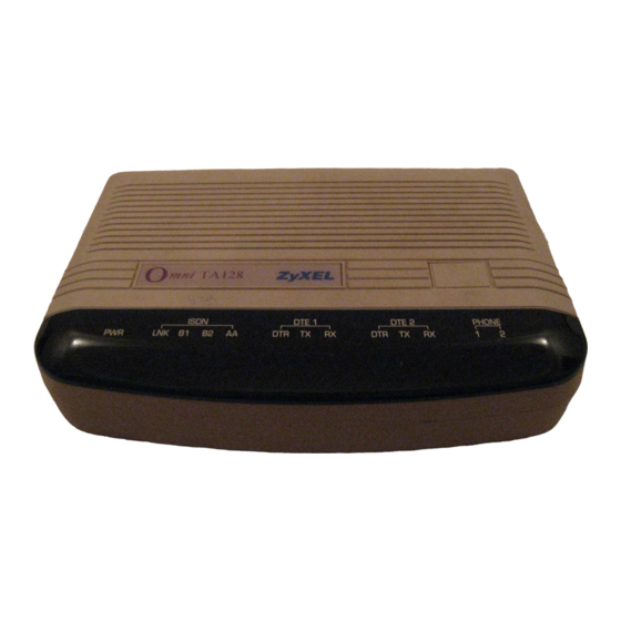
Page 22: Ta128 Front Panel
TA128 Front Panel Figure 2-4 TA128 Front Panel The LED Indicators PWR - The power on LED lights up when the TA128's power is turned ON. LNK - The Link LED lights up when the link with the local switch is active and flashes when attempting to make a connection. -
Page 23: Front Panel Switch
DTR - The data terminal ready LED lights up when the DTE or computer connected to the DTE Port indicates that it is ready for communication by raising the corresponding RS-232 signal. TX - The transmit data LED flashes when the DTE/Computer is transmitting data to the DTE Port of the TA128. -
Page 25: Configuring Your Isdn Line And Network
Configuring Your ISDN Line and Network The set up procedure for the TA128 needs to be done only once. The settings will be stored in non-volatile RAM. The only time you will need to reconfigure your line is when you perform a hardware reset on your TA or when you change options on your ISDN line. -
Page 26: Configuring Your Ta Using A Terminal Program
Configuring your TA using a Terminal program If you are not using the ISDN configuration utility that is packaged with the TA128, you will need a terminal program with which to configure the unit. The TA128 should work with any asynchronous terminal program that can communicate directly with one of the communication ports on your system. - Page 27 Type: ATI1<Enter> TA128 should respond: TA128 USA: V 1.00a (Firmware version number) 7607 (Firmware checksum will change based on your firmware version) Once the TA128 accepts the commands that you typed, it is ready to be programmed and ready to operate with your ISDN network. If you do not receive any response from the device, go over your installation procedures again or contact ZyXEL Technical Support.
-
Page 29: Isdn Communication Basics
ISDN Communication Basics In this chapter, we will cover how to initiate and receive calls over digital lines using your TA128. Understanding AT Commands AT commands are used to configure and control the TA128. Command statements are usually sent to the TA by being typed from the computer keyboard. -
Page 30: Supported At Command Types
This confirms that the TA and your computer are communicating correctly. Supported AT command types: Type of AT Command Example Basic AT (Hayes compatible). Basic AT$ (on line help). Extended AT&. AT&F Extended AT* command. AT*I1 S-Register command. ATS0=1 S-Register bit-mapped command ATS13.1=1 (set S- Register bit 1 equal to 1). -
Page 31: Outgoing Calls
The TA128 supports either verbose result code (i.e. “OK”) or numerical result code (i.e. “0"). You can use ATVn command to set it one way or the other: Command Description ATV0 Select numerical result code. ATV1 Select verbose result code. Outgoing Calls The TA128 has 3 modes in which to send communication over ISDN network. -
Page 32: Dialing Out For Analog Adapter Port 1
ATS83.7=1<enter> To disable it, type: ATS83.7=0 <enter> Dialing out for Analog Adapter Port 1 Using the “A” command following the “ATD” will tell your TA128 to automatically switch call to analog adapter, Phone 1, once dialing is complete. Type: ATDA17146930762<enter> You must have an analog modem connected to your analog NOTE port before you issue this command. -
Page 33: Placing The Call
The factory default is AT&O2. This means the TA will select ISDN data mode when you do not specify which communication mode to use (i.e. ATD or ATDT). Placing the Call To initiate a call, choose the proper communication mode and configure the mode according to the bearer service (or protocol) you want to use. -
Page 34: Digital Data
comes in, the TA128 will send the call to the analog port as the factory default, Phone 1 and then Phone 2. Digital Data The TA128 currently supports Circuit Switched Data (CSD) for ISDN data applications. The CSD protocols supported by the TA128 include: PPP, MPPP, V.120, X.75, and V.110. -
Page 35: Answering A Call Using Msn
need to change the maximum sending frame size, the ATCL command should be used. Type: ATCL252<Enter> (Set the frame size to 252 octets, user value between 1-2048) TA128 responds: Type: ATCL?<Enter> (To inquire about the current setting of the packet length) TA128 responds: Maximum user data length in a packet (byte) : 252 Answering a Call using MSN... -
Page 36: Data Over Speech Channel
AT&ZI? can be used to display the MSN numbers. The factory default for these numbers are UNASSIGNED. If an incoming SETUP message is offered with addressing information (i.e. the appropriate part of the called_party_number), this address will be compared with the MSN numbers assigned by the AT&ZIn=s commands. -
Page 37: Ambiguity Resolution Switch For Voice Calls
with the address of the incoming call, the TA128 will, by default, ignore the call as it may be intended for other devices that share the same S/T interface (S0 bus) with the TA128. If you want the TA128 to answer inbound calls using all possible protocols, you can set the best-effort call answering bit as follows: Command Function... - Page 38 2. By the Multi Auto-answering process. The TA128 determines the protocol by monitoring the B channel signal sent by the calling site. With either method, the data call can be identified by the TA128 to be X.75, V.110, V.120, or PPP, MPPP Async-to-Sync conversion. If the address-matching process is again unable to tell which protocol to use, the TA128 will go into its “Multi Auto-answering Routine,”...
-
Page 39: Setup For Windows 95 And Nt 4.0
Setup for Windows 95 and NT 4.0 This chapter contains step by step procedures for installing the Windows 95 and NT drivers, and configuring Dial-up Networking for the TA128. Installing the Windows 95 Driver (INF file) If your computer supports Plug & Play be sure your TA128 is powered on before starting your computer. - Page 40 4. Click the “Have Disk” button. 5. Insert the ZyXEL Windows 95 driver disk into your floppy drive and click OK. If you have downloaded an updated INF file from ZyXEL’s FTP, website, or BBS, use Browse to find the location of the updated .INF file, click Open, then click OK.
- Page 41 recommend that you check with your ISP to verify the protocol they use. If you are connecting to an Internet Service Provider (ISP), select: • ZyXEL TA128, PPP 64K If the ISP has not upgraded to an ASEND compatible server, select: •...
-
Page 42: Configuring Windows 95 Dial-Up Networking
2. Click Close. This completes the installation of your TA128 modem driver. You may now use programs such as “Dial-Up Networking” with your TA128. Configuring Windows 95 Dial-Up Networking This section assumes you have already fully installed Windows 95. If you have not installed the Dial-Up Networking feature in Windows 95, please install it before you continue. - Page 43 2. Choose a name for your connection and select your modem type from the drop down window. Then click on the “Next” button. 3. Type the phone number of your ISP or of host you will be calling. Click on the “Next” button. 4.
- Page 44 6. Make sure your TA128 appears in the “Connect Using” box. Then click on the “Server Type” button. • These options are mostly host or server specific. • If you are using PPP, use the default settings shown above. • If you are connecting to a LAN, then select “Login to Network.”...
- Page 45 • If you are logging on to a Microsoft Windows network, select “NetBEUI.” • If you are logging on to a Novell network, then select “IPX/SPX Compatible.” • If you are logging on to an Internet connection, then select “TCP/IP.” 7.
-
Page 46: Capi Installation
9. If the User name and Password are incorrect or are not there, type them in. Click on the Connect button and your TA128 will dial the number and establish a connection. CAPI Installation Follow the steps below to install the ZyXEL Internet Configuration Manager and ZyXEL CAPI drivers: 1. - Page 47 4. From the Question dialogue box click No if you do not wish to setup Multiple Subscriber Numbers. This completes CAPI installation. If you click Yes continue with the steps below: Only CAPI 1.1a requires setup of Multiple Subscriber Numbers. 5.
-
Page 48: Point-To-Point Protocol (Ppp)
Point-to-Point Protocol (PPP) Introduction Point-To-Point Protocol is designed for simple links which transport packets between two peers. These links provide full-duplex simultaneous bi-directional operation, and are assumed to deliver packets in order. PPP is intended to provide a common solution for easy connection for a wide variety of hosts, bridges and routes. -
Page 49: Feature List
Data will be transmitted only when the link is in the open phase. Negotiation details are described in RFC1661. Feature list Async to Sync Conversion PPP uses HDLC-like framing as encapsulation, which can be bit- oriented or character-oriented. Most ISDN routers use bit-oriented HDLC framing, also known as synchronous transmission. -
Page 50: Compression Control Protocol (Ccp)
form by CHAP. Sometimes CHAP can not be supported by the ISP. You may set S87.2=1 to use PAP only. If you do not want to do authentication at all, set S118.3=1 to disable the conversion. Disabling authentication may cause problems in Windows NOTE CHAP is described in RFC1994 and PAP is described in RFC1334. -
Page 51: Multilink Ppp
• AT&K44 - Enable CCP negotiation. Multilink PPP There are two B channels in basic rate ISDN. This offers the possibility of opening multiple simultaneous channels between systems giving users additional bandwidth on demand. Multilink PPP is a method for bundling both B channel into one PPP link for higher throughput. -
Page 52: Bandwidth On Demand (Bod)
delay time between on-hook phone and channel reestablishment. The delay for reestablishing the channel is 10 seconds. During call bumping, the traffic for BOD is still under calculation. In other words, the add persist time is calculated from the time when the traffic is above the add threshold whether or not the phone is on- hook or off-hook. -
Page 53: Bacp/Bap
• ATJAn - Add traffic threshold for n K bits per second, n = 48 (default). • ATJSn - Subtract traffic threshold for n K bits per second, n = 32 (default). • ATKAmn - Add persist time for n period in m unit, n = 0 - 127, m = s for seconds and m for minutes. -
Page 55: 110 And Synchronous Mode Communications
V.110 and Synchronous Mode Communications V.110 is most popular in Japan. The table below shows the specifications of different ISDN protocols: Synchronous V.110 X.75/V.120 Layer 1 Transparent 80 Bits HDLC Framing Layer 2 None None LAPB/LAPD Layer 3 None None ISO8208 T.70 NL/ V.120 Error Control... -
Page 56: Making V.110 Calls
DCE will report “RING” and will also make an audible ring notification. Making V.110 Calls Before the ATDIxxx command is given to place the call, you need to make sure that the TA128 is in asynchronous mode (AT&M0). Then use the following commands to configure V.110: AT Command Description ATB10... -
Page 57: V.25Bis Command Set
There are two modes of synchronous operation: 1. Asynchronous commands, synchronous data (AT&M1): The TA128 accepts AT commands in asynchronous mode. Once the call is connected, it enters synchronous mode for data transmission. 2. Synchronous mode (AT&M3*I1): The TA128 accepts synchronous commands from V.25 bis or a PC with an add-on synchronous card, and exchanges data synchronously with a remote TA. -
Page 58: Dtr Drop-Dialing Operation
Command Messages Receive incoming calls. Reject incoming calls. Changes to asynchronous AT command mode. Indicator Messages Call connect. Incoming call. Valid command. Invalid command. CFLxx Call Failure. Answer tone is not detected. Abort call. Engaged tone. Number is not stored. Ring tone. - Page 59 to save phone number to NVRAM. 2. Issue the command AT*D0 To set phone number 0 as the DTR drop destination phone number. 3. Issue the command AT&D1 Enable DTR dialing operation. 4. Turn the TA off and back on.
-
Page 61: 120 Isdn Communications
V.120 ISDN Communications This chapter describes how to set-up and configure your TA128 with the V.120 ISDN protocol. The table below shows the specifications of different ISDN protocols: V.110 V.120 X.75 80 Bits HDLC HDLC Layer 1 Framing Layer 2 None LAPD LAPB... -
Page 62: Configuring The V.120 Mode
support out-of-band signaling, network signals are transmitted through the B channels. This reduces the bandwidth to 56Kbps. When you are making a V.120 call, make sure that the communication supports out-of-band signaling. If it does not support out-of-band signaling, you will need to set your TA128 to 56K mode using the AT&E1 command (AT&E0 to set it back to 64k mode.) If your TA128 is on the receiving end, you can keep the setting at AT&E0, 64k data mode. -
Page 63: Dialing In V.120 Mode
All the above commands can be simplified by combining all of the commands onto one line as follows: AT&B20&E1&WZ0<Enter> Dialing in V.120 mode Finally, use the ATDn command to make the call (n is the phone number you wish to dial). Once the connection is made, you should see the following connect message. -
Page 64: Speeds Of 128Kbps
Band Signaling is used). It is called a “Bundle Connection”. The type of channel bundling described in the V.120 section is supported only between the following ZyXEL products: omni.net, Omni TA128, or Elite 2864I, and uses Multiple Link Protocol (MLP) and “cFos” channel bundling (CCB). Identifying your line provisioning... -
Page 65: Dialing Pre-Stored Phone Numbers
Once this is done, the ATD command will generate two consecutive SETUP messages to invoke bundle initiation. For the Northern Telecom switch, each BRI phone number can only be called once at any given time. So if you dial this number, it will report “busy”... -
Page 66: Error Correction And Data Compression With V.120
to dial the (n+1)th phone number for the first connection and the (m+1)th phone number for the second connection. For example, ATDIS0+S1<Enter> will dial the number stored in location ‘0’, and the number stored in location ‘1’ for the bundle connection. -
Page 67: Bundle Connection With V.42Bis Data Compression
Bundle Connection with V.42bis Data Compression If both sites have set AT&K44 to enable V.42bis negotiation then XID frames will be exchanged through the main B channel which corresponds to the call established by the first SETUP message. Only one data compression channel will be used in bundle connections. - Page 68 synchronous V.120 code to fill in the additional information octet. This approach might not work all the time.
-
Page 69: 75 Isdn Communications (Europe)
X.75 ISDN Communications (Europe) This chapter will describe how to set-up and configure your TA128 with X.75 protocol. The table below shows the specifications of different ISDN protocols: V.110 V.120 X.75 Layer 1 80 Bits HDLC HDLC Framing Layer 2 None LAPD LAPB... -
Page 70: Answering An X.75 Call
Answering an X.75 call There is no need to configure the ISDN mode to the protocol of an incoming call. The TA128 will be able to determine the correct protocol to use by examining the data coming in from the remote site if the device is set to auto-answer or once an answering command is issued. -
Page 71: Making A Bundled Call With X.75
For European ISDN (DSS1), the Low-Layer-Compatibility (LLC) information element in the SETUP message can be used to specify the layer 3 protocol. Since this is an option for ISDN switches, some of the switches might not deliver the LLC information element to the remote end. -
Page 72: Dialing Pre-Stored Phone Numbers
bundle request. The two data calls are established following normal call control procedures. That is, the network treats them as two independent calls. Both TA’s use X.75 Multiple Link Protocol or 'cFos' channel bundling protocol to coordinate the two B channels. The former would need an overhead of two octets for each packet. -
Page 73: Bundle Connection With V.42Bis Data Compression
• AT&K00 - (disable V.42bis on ISDN call) For X.75, to negotiate compression parameters with the remote ISDN terminal, we exchange XID frames before the Link Layer is established. The calling site will send an XID frame with V.42bis request to the called site. If the called site understands this XID's meaning, it will reply to an XID frame with a V.42bis request. -
Page 75: Handling Analog Calls
Handling Analog Calls Analog adapters enable you to connect analog devices (e.g. telephone, fax, PBX, or modem) to an ISDN Basic Rate line. Any conventional analog telephony equipment which supports DTMF tone/pulse dialing can be plugged into any one of the two RJ-11 sockets (labeled phone 1 and phone 2) on the back of the TA128. -
Page 76: Placing A Call From The Analog Adapter
AT Command Description ATS84.5=1 use. AT&ZIn=s MSN setting, assign Called phone number, “s,” to be answered by “n” port (where n=6 for Phone 1 and n=7 for Phone 2). AT&ZI6=s Assign the Called phone number for analog adapter, Phone 1. AT&ZI7=s Assign the Called phone number for analog adapter, Phone 2. -
Page 77: Accepting An Incoming Call
Use ATDAs (ATDBs) to place a call from analog adapter 1 (analog adapter 2) Once the analog adapter's hook sensor detects that the telephone device’s handset is off hook, it sends a SETUP message to the ISDN central exchange to request a connection. One B channel, if available, will be assigned to this connection and the exchange will wait for the dialed number to route the call. - Page 78 Phone 1 Phone 2 Global Call S120.2 AT&Ln (No Called (Default=0) (Default Phone 1 Phone 2 Matched Matched Party No.) n=0) ü û û Ring û ü û Ring û Unassigned Unassigned Ring Ring û Unassigned Unassigned Ring û Unassigned Unassigned Ring ü...
-
Page 79: Feature Phone
Feature Phone The TA 128 supports ZyXEL’s powerful and advanced feature phone operation. By connecting to the TA 128’s POTS ports, you can get the benefits of analog phone services, plus additional features over your ISDN line. The Flash key All feature phone operations start from the Flash key. -
Page 80: Call Waiting
InterCom: ( ñ è H Flash è H #2 Call Waiting The call waiting feature enables you to place a call on hold by pressing the Flash key. If you press the Flash key again, the call waiting function will be disabled and return to the previous call. Call Waiting: H Flash Placing a second call When you have an active call on line, you may follow the procedures... -
Page 81: Call Broker
• To accept the call, press the Flash key and 0 to accept the second call and place the first call on hold. Accept the second call: H Flash è H #0 • To reject the second call press the Flash key and 5. Reject the second call: H Flash è... - Page 82 Two local parties connected to one remote party: 1. Place a call to the other local party by pressing the Flash key and 2. After they answer, place them on hold by pressing the Flash key and 0. 3. Place a call to the remote party. 4.
-
Page 83: Advanced Isdn Call Control
Advanced ISDN Call Control Call Control for DSS1 (Digital Subscriber Signaling #1) In order to initiate a DSS1 ISDN call, two information elements are necessary: • Bearer Capability - indicates what kind of bearer service is desired. It is also used for compatibility checking in the addressed entity. - Page 84 between the call originating entity (e.g. the calling user) and the addressed entity. Outgoing High-Layer-Compatibility can be controlled by setting the value of S-register S(108+n) as follows: • n=0 - (S108) Setting for analog adapter 2. • n=2 - (S110) Setting for ISDN data calls. •...
-
Page 85: Control Of Isdn Phone Number And Sub-Address
S108.n= Function S80.n=0 Disable outgoing Low-Layer-Compatibility (default). S80.n=1 Enable outgoing Low-Layer-Compatibility. Example: ATS80.4=0 disables Low-Layer-Compatibility message for Analog Port 2. Control of ISDN Phone Number and Sub-address The Calling-Party-Number information element identifies the origin of a call, and the Called-Party-Number information element identifies the destination of a call. -
Page 86: Call Control For 1Tr6 (Old German Isdn)
Nn is the identifier of numbering plan: • N0 - unknown (default if Nn is omitted). • N1 - ISDN numbering plan (Rec. E.164) (default for Australia if Nn is omitted). • N3 - data numbering plan (Rec. X.121). • N4 - telex numbering plan (Rec. F.69). •... -
Page 87: Control Of Outgoing Service Indicator
• Service Indicator - Determines what kind of bearer services are desired. • Destination Address - Provides information for the telephone company to direct the call to the remote party. Control of Outgoing Service Indicator The Outgoing Service Indicator will be assigned when you configure the B channel protocols using the command ATBnn. - Page 88 With its highly integrated, multi-function features, the TA128 can be viewed as a “black box” containing multiple distinct terminals. Each of these "internal terminals" can be assigned one EAZ using the command AT&ZIn=m, where n=0-7 and m= 0-9. Command Function &ZI0=m assigns EAZ for X.75.
-
Page 89: Answering A Call
Each type of outgoing call can be assigned with one origination EAZ by using the command AT&ZOx=Origination_EAZ, (where x = I for ISDN data calls, A for the analog adapter 1, and B for the analog adapter 2). The command AT&ZOx=// removes the assignment of the origination EAZ. -
Page 90: Answering A Call For 1Tr6
terminals" can be assigned one ISDN number using the AT&ZIn=xxxx... command. The number assigned by AT&ZIn=xxxx... can be interpreted as either the MSN or the subaddress. This is determined by the bit 5 of S119 as follows: • S119.5=0 - the number is treated as the MSN (default). •... -
Page 91: Ambiguity Resolution Switch For Voice Calls
If you want the TA128 to answer inbound calls as often as possible, you can set the best-effort call answering bit as follows: • S119.3=0 - Answer calls only when numbers match (by default). • S119.3=1 - Best effort call answering. Ambiguity Resolution Switch for Voice Calls For a voice or voice-band-data call, if the &ZI number assignment can tell which of the analog adapters is being addressed, then the call... -
Page 92: Data Call Indication
Data Call Indication Data calls are accepted the same way as in any TA. When alerted, the TA128 will send the first RING message to the DTE with a format as follows: RING <CR><LF> [FM:[[Prefix]Calling-Party-Number][/Subaddress/]] [TO:[Called-Party-Number][/Subaddress/]] <CR><LF> RING <CR><LF> RING <CR><LF> .. -
Page 93: Disable Inbound Call Connection
Disable inbound call connection In some cases, the user may desire the TA128 to not answer any incoming calls. This can be done by setting the bit 0 of S-register S118: • S118.0=0 - Enable the TA128 to answer a call (by default). •... -
Page 94: Placing A Call For 1Tr6
• Y1 - international number. • Y2 - national number. • Y3 - network specific number. • Y4 - subscriber number. Nn is the identifier of numbering plan: • N0 - unknown (default if Nn is omitted). • N1 - ISDN numbering plan (Rec. E.164). •... -
Page 95: Leased Line Isdn
• Y0 - unknown (default if Yn is omitted). • Y1 - international number. • Y2 - national number. Nn is the identifier of numbering/addressing plan: • N0 - unknown (default if Nn is omitted). • N1 - ISDN numbering plan (Rec. E.164). The destination_address is the ISDN phone number of the called party. - Page 96 For some protocols that are originate/answer mode sensitive, use the following command to configure the originate/answer mode: AT*Mn leased line auto-handshake mode selection S14b0. AT*M0 leased line auto-handshake for Originate mode. AT*M1 leased line auto-handshake for Answer mode. If the leased line mode is selected after power up, the following commands can be used to make a leased line connection: ATDB1 use B1 channel in Originate mode.
-
Page 97: Security Functions
Security Functions The TA128 provides security functions that may be enabled to prevent unauthorized connections. Two types of security functions are provided. Security Types and Levels Type 1 security is to be used when the remote TA is a ZyXEL ISDN Type 2 security is to be used with non-ZyXEL remote TA’s. -
Page 98: Level 1 Security
Level 1 security Will only perform password checking. With Level 1 security, the local TA will maintain the connection if the password is matched, otherwise the line will be disconnected. Level 2 security Provides Calling Party Number checking and call-back, the call-back number is pre-stored in the password table. -
Page 99: Setting And Modifying Passwords
Level 1 Level 2 Level 3 Password Check Call back Prompts the CPN Check OK and S119.6=0 remote user to enter call back number Keep the for calling CPN Check OK and S119.6=1 connection back. Disconnect CPN unmatched Call back using CPN not Available the corresponding... -
Page 100: Non-Password Auto Call Back Function
You will be asked for the original password and a new password. Then re-enter the new password for verification. For example: Password: ******** (Enter current supervisory password) Password: ******** (Enter new supervisory password) Verify: ******** (Enter the new supervisory password again) Use command AT*Hn to modify the “n”th user password. -
Page 102: Upgrading Your Ta128
Upgrading Your TA128 This chapter describes how to upgrade flash EPROM firmware when it is available. Upgrading with Flash EPROM Your TA128 employs a flash EEPROM (Electronic Erasable Programmable Read Only Memory) that lets you conveniently update firmware and program the TA with new features and enhanced functions. -
Page 103: Kernel Mode
ATUPX<Enter> TA128 responds: You have chosen Xmodem (128 octets of data with checksum) protocol to update your TA. Data in Flash ROM will be erased !!! Are you sure (Y/N) ? 3. Press Y. The following message then appears: Start programming, please upload. 4. -
Page 104: Dte Port 2
DTE Port 2 This chapter describes how to set the TA128 into Two-DTE Port and One Analog Port mode in which two users can use the TA128 simultaneously to place two independent calls to access the Internet. The two-DTE-port feature is also ideal for Service Providers in that two users can be serviced concurrently through two COM ports, one TA128, and one ISDN BRI line. -
Page 105: Configuring Dte Port 2
Mode DTE Port 1 DTE Port 2 POTS Port POTS Port û ATS125.0=0 One DTE Port and Two POTS Ports (by default) û ATS125.0=1 Two DTE Ports and One POTS Port Configuring DTE Port 2 The function of DTE port 2 is quite simple compared with those of DTE port 1. -
Page 106: Basic "At" Command Set
DB9 Female The following tables list all of the AT commands for DTE port 2 supported by the Omni TA128. An asterisk * following a command option or value indicates that it is a default setting when the modem is shipped. - Page 107 Subscriber number Abbreviated number Type of sub-address, NSAP with AFI=$50, IA5 characters Type of sub-address, user specified, IA5 characters Unknown numbering plan ISDN/Telephony numbering plan (CCITT E.164/E.163) Data numbering plan (CCITT X.121) National standard numbering plan Private numbering plan Called party sub-address delimiters Format [[Yn][Nn]called_party_number]...
- Page 108 1281 (USA) 1282 (DSS1) 1283 (1TR6) Display product information and ROM checksum Results: Omni TA128 <switch>: V x.xx where <switch>= USA, DSS1, or 1TR6 Display Microsoft PnP code Return to on-line state S0=n Set S-register s0. 'n' must be a...
-
Page 109: Extended "At&" Command Set
Extended "AT&" Command Set Command Options Function and Description Ref. &Cn Carrier Detect (CD) options &C1 * CD tracks presence of carrier All other values are invalid &Dn Data Terminal Ready (DTR) options. &D2 * 108.2, Data Terminal Ready, DTR OFF causes the TA to hang up. -
Page 110: Setting Of Dte Port 2 Speed
Command Options Function and Description Ref. &V7 View analog adapter, Phone 2 setting &ZIn=s s=phone MSN setting. number Assign the phone number for DTE port 2 All other values are invalid &ZI? Display the phone number for various B-channel protocols &ZO? Display the &ZOn setting &ZOn=x... - Page 111 outgoing SETUP message, it can be pre-stored using the AT&ZOI=xxxx command. Once the PPP connection is established, the TA128 will indicate the connection message with DTE speed as follows: CONNECT 115200 PPP Use ATV0, if numerical result code is required. An X.75 or V.120 can be placed after selecting the protocol using ATBnn.
-
Page 112: Diagnostics
Diagnostics This chapter provides diagnostic tables for the TA128. The TA128 can perform its own diagnostic tests, providing you with valuable information. Diagnostics The TA128 ISDN TA provides several diagnostic capabilities: • Power-on Self-test • Local Digital Loopback Test • Diagnostic Command •... -
Page 113: Isdn Loopback Test (At&T9)
ISDN Loopback test (AT&T9) The AT&T9 command will invoke an ISDN loopback test connection. The loopback point is in the S/T interface chip (Siemens 2086 chip) or the U interface chip (Siemens 2091 chip) just behind the line transformers, thus it checks almost every part of the ISDN TA and RS-232 cable except the passive front-end of the ISDN S/T or U interface. -
Page 114: The Diagnostic Command (Atcg)
Type: AT&T11<Enter> TA128 responds: Dial your_isdn_number Loop from B1 to B2 through the switch established! Sending and receiving data..B1/B2 loopback test successed. Disconnecting..NO CARRIER The Diagnostic Command (ATCG) The ATCG command can be used to test and isolate hardware problems. -
Page 115: Using The Embedded Protocol Analyzer
EPA is designed for hobbyists as well as users with technical backgrounds. The EPA enables you to examine messages exchanged between your Omni TA128 and the Central Exchange office when making an ISDN call. You can review the packets sent or received through the B-channel (for X.75 or V.120) to or from the remote... - Page 116 CAPI internal interface. The CAPI internal interface is used with the ZyXEL CAPI driver. The ZyXEL CAPI driver communicates with the Omni TA128 through this internal interface. It is not recommended that users get involved in this internal interface. The AT commands/responses, on the other hand, are in a standard user interface.
-
Page 117: Analyzing The Captured Data
AT Command Description Disable the capture of B-channel protocols (default) Enable the capture of B-channel protocols ATCCn Disable the capture of DTE-DCE interface protocols(default) Enable the capture of DTE-DCE interface protocols The EPA starts to capture data when the command ATCT is issued. This capturing process will continue until the command ATC$ is issued. - Page 118 Function Description Display to the end of buffer Cursor Scroll one line up down Page down Display the next page Home Display the first page Cursor up Scroll one line down Page up Display the previous page Q, q Quit Quit embedded protocol analyzer...
-
Page 120: At Command Set Reference
AT Command Set Reference Operation Modes of the DTE Interface There are two operation modes for the DTE interface: • Simplex mode - used for conventional AT Command operation. • Multiplex mode - used as an internal interface for ZyXEL CAPI drivers. -
Page 121: At Command Descriptions
AT Command Descriptions An AT Command is a command in asynchronous data format issued by the computer to the TA through the asynchronous computer- modem interface. AT Commands control the TA's behavior and actions. To send an AT Command from a computer to the TA, you must be running communication software and the TA must be in the command state. - Page 122 Command Options Function & Description Ref. A> Re-execute the last command once or repeat the last call up to 9 times. (See also S8) <any key> Terminate current connection attempt when enter in handshaking state. Escape sequence code, entered in data state, wait for TA to return to command state.
- Page 123 Command Options Function & Description Ref. V.110 user rate = 14400 bps. V.110 user rate = 19200 bps. V.110 user rate = 384000 bps (sync only). V.110 user rate = 576000 bps (sync only). V.120 PPP async to sync conversion. SLIP async to sync conversion.
- Page 124 Command Options Function & Description Ref. Enable the call bumping function. Call bumping(Call bumping) for S85.0 MPPP and CCB. Disable Call bumping function. Enable Call bumping function . Display the accumulated charging unit of the last call. CI<prefix> Prefix number string to be added to the Calling-party-number before indicating to the DTE when the type of number denotes...
- Page 125 Command Options Function & Description Ref. Dial s (numbers and options) that follow (see also S38.0, S35.4). The options of s are listed as follows: Pause for a time specified in S6. Remaining digits will be dialed as in-band DTMF. Unknown type of number International number National number...
- Page 126 Command Options Function & Description Ref. Dial s (number and options) that follows for the Analog adapter, Phone 2. Connection option if leased-line S85.0 mode is selected after power-on. Use B1 channel in originate mode. Use B2 channel in originate mode. Use B1 &...
- Page 127 Command Options Function & Description Ref. Display product code, same as 'ATI' Results: 1291 (USA) 1292 (DSS1) 1293 (1TR6) Display product information and ROM checksum. Results: TA128 <switch>: V x.xx where <switch>= USA, DSS1, or 1TR6 Display link status report Display Microsoft PnP code Display PPP status.
- Page 128 Command Options Function & Description Ref. n=0-3 Ring volume control.'N0' will S24.0-1 disable the audio ring function Return to on-line state n=0-6 D channel protocol selection (USA) for American Version P0 * Northern Telecom proprietary ISDN National ISDN 1 (1 SPID) National ISDN 1 (2 SPID) Reserved AT&T custom point-to-point...
-
Page 129: Description Of Ati3 Output
Command Options Function & Description Ref. Download firmware to the Flash EPROM using Xmodem protocol. Sets display type for Result Codes. S23.6 Display result code in numeric form. (See also S35.7 and the result code table of 'ATXn'). V1 * Display result code in verbose form. -
Page 130: Extended "At&" Command Set
Output Parameter Output Value Description Connect DTE Speed Current on-line DTE speed. Error Control Level Error control protocol used for current session. Protocol Link Speed Current on-line DCE speed, line speed. Octets Received Number of data octets received from remote. Octets Sent Number of data octets sent to remote. - Page 131 Command Options Function & Description Ref. &D3 Same as &D2 but DTR OFF causes the TA to hang up and reset from profile 0. &En B channel line speed for ISDN data S118.2 call &E0 * 64Kbps &E1 56Kbps (Default for American ISDN) &F Load factory settings to RAM as...
- Page 132 Command Options Function & Description Ref. &Ln Analog port selection during call S84.5 answering. &L0 Set priority to analog port, Phone 1. &L1 Set priority to analog port, Phone 2. &Mn Bundle selection (See also S100). S14b6-7 &M0 * Asynchronous mode with data buffering.
- Page 133 Command Options Function & Description Ref. &V0 View current active settings. &V1-4 View the (n-1)th user profile settings. &V5 View factory default settings. &V6 View analog adapter, Phone 1 setting &V7 View analog adapter, Phone 2 setting &Wn n=0-3 Write current settings to user profile n in non-volatile RAM.
-
Page 134: Extended "At*" Command Set
Command Options Function & Description Ref. Assign the phone number ‘s’ for the analog adapter, phone 2. &ZI? Display the phone number (including subaddress , if any) for various B channel protocols. &Zox=s Write own phone number (including subaddress, if any) &ZO? Display the &ZOn setting. - Page 135 Command Options Function & Description Ref. Enable type 1 security, with password check (ZyXEL to ZyXEL only). Enable type 1 security, with password check and call back (ZyXEL to ZyXEL only). Enable type 2 security, with password check. Enable type 2 security, with password check and call back.
- Page 136 Command Options Function & Description Ref. View the Call-back Number table...
-
Page 138: Status Registers And Result Codes
Status Registers and Result Codes S-registers (Status Registers) contain values that determine and reflect how your Terminal Adapter (TA) operates and executes commands. You can read the values and change them, either using terminal commands or the TA's panel controls with the same results. Every user profile corresponds to a separate set of S-register values, but when we mention S-registers, we are referring to the ones that correspond to the active profile. -
Page 139: Setting S-Registers
• n=1-4 - View settings for user profile number (n-1). • n=5 - View the factory default settings. • n=6 - View the analog adapter’s setting, Phone 1. • n=7 - View the analog adapter’s setting, Phone 2. The S-register values may be displayed in either Decimal or Hexadecimal format when using the preceding commands. -
Page 140: S-Register Descriptions
Convert it to binary, using the following weight table: Binary value Decimal value Hexadecimal value 00000001 00000010 00000100 00001000 00010000 00100000 01000000 10000000 To set bit 3 to 1 (binary), do a logic OR operation with the value. Operation Example-1 Example-2 Binary Dec. -
Page 141: Basic S-Registers "Atsn=X
Basic S-Registers "ATSn=x" Command Function & Description Ref. Set the number of rings on which the TA will +000 answer. A 0 value disables auto-answer. Counts and stores number of rings from an +000 incoming call. Define escape code character, default <+> (43 +043 dec.). - Page 142 Command bit dec hex Function and description Ref. 64 40 Profile 2 as active settings after power ON. 96 60 Profile 3 as active settings after power on. 128 80 * Factory default as active settings after power ON. S16= dec hex Test status register.
- Page 143 Command bit dec hex Function and description Ref. According to CCITT (see also &S1 S44.4, S41.5). CD always On. &C0 16 10 CD tracks presence of data &C1 connection (see also S38.3). 6-7 0 Assume DTR always On. &D0 64 40 108.1, DTR Off-On transition &D1 causes dial of the default number.
- Page 144 Command bit dec hex Function and description Ref. 128 80 TA does not return result code (see S40b1). S24= bit dec hex Bit mapped register. 0-1 0-3 0-3 Ring volume control, N0-3 increments of 1 in decimal. Ignore S21.1-2 when Phone 1 key pad dialed.
- Page 145 Command bit dec hex Function and description Ref. Disable aborting from terminal during modem handshaking. 16 10 When Data/Voice with is pressed, TA will dial the default number. 128 60 Enable extended numerical result codes from 50-71 when S23.6 an error corrected connection is made.
- Page 146 Command bit dec hex Function and description Ref. S40= bit dec hex Bit mapped register. +000 No result code displayed in answer mode. S41= bit dec hex Bit mapped register. +000 Enable CCITT signals 140 and 141 on EIA-232D interface. 32 20 DSR follows DCD and pulses &Sn (see S44b4).
- Page 147 Command bit dec hex Function and description Ref. S50= Inactivity timer for RS-232 +000 Port. Each unit = 10 sec. 000 disables. S56= Hook flash detect time for +050 Analog Adapter (POTS port); units 10ms. S61= bit dec hex *0 0 MP data sent in rotate mode.
- Page 148 Command bit dec hex Function and description Ref. *0 0 POTS port 1 is connected to a telephone. 16 10 POTS port 1 is connected to a fax/modem. *0 0 POTS port 2 is connected to a telephone. 32 20 POTS port 2 is connected to a fax/modem.
- Page 149 Command bit dec hex Function and description Ref. X.75 64000 Transparent X.75 56000 Transparent X.75 64000 T.70 X.75 56000 T.70 X.75 64000 BTX X.75 56000 BTX V.110 64000 V.110 56000 PPP async to sync 64K PPP async to sync 56K SLIP to sync HDLC conversion 64K.
- Page 150 Command bit dec hex Function and description Ref. S84= bit dec hex Embedded Protocol Analyzer control. Capture DTE-DCE interface protocol information. Capture B-channel (X.75 or V.120) frames. Capture D-channel protocol information. *0 Display S register value in decimal format. Display S register value in hex format.
- Page 151 Command bit dec hex Function and description Ref. Northern Telecom proprietary ISDN. National ISDN 1 (1 SPID mode). National ISDN 1 (2 SPID mode). Reserved. AT&T proprietary point-to- point. AT&T proprietary point-to- multi-point (1 SPID mode). AT&T custom point-to- multipoint (2 SPID mode). S87= bit dec hex *0 0...
- Page 152 Command bit dec hex Function and description Ref. *0 0 DTE port 2 only answers the matched MSN incoming data calls. 128 80 DTE port 2 answers incoming calls when DTE port 1 is busy. S89= bit dec hex Bit-mapped register. Disable the metering pulse of analog adapter, Phone 2.
- Page 153 Command bit dec hex Function and description Ref. Daten bertragung 64 Kbps. The defaults are : * s104=1 - for a/b adapter 2 * s105= - reserved * s106=7 - for ISDN data * s107=1 - for a/b adapter 1 S108+n= dec hex Outgoing Service Additional (for 1TR6 only) Information...
- Page 154 Command bit dec hex Function and description Ref. ---- Even parity 1--- 11--- 1200 bps 11--- 2400 bps 11--- 4800 bps 11--- 9600 bps 11--- 14400 bps 11--- *19200 bps 01--- 38400 bps 1010- Sync. V.110 10100 1200 bps 10100 2400 bps 10100 4800 bps...
- Page 155 Command bit dec hex Function and description Ref. S108+n= dec hex High Layer Compatibility (Non-1TR6) n=0, analog adapter, Phone 2 n=2, ISDN data n=3, analog adapter, Phone 1 0 * 0 No High-Layer-Compatibility information element will be sent Telephone Facsimile Group 2/3 40 28 Teletex service (Rec.F.220) 49 31 Teletex service (Rec.F.200) 50 32 Information Interworking for...
- Page 156 Command bit dec hex Function and description Ref. Enable CHAP option for PPP/MLPPP. 0 * 0 Use 3.1KHz Bearer service whenever possible for analog adapter, Phone 2 16 10 Use Speech Bearer service whenever possible for analog adapter, Phone 2 0 * 0 Use 3.1KHz Bearer service whenever possible for analog...
- Page 157 Command bit dec hex Function and description Ref. Inbound call accepted using default protocol when no MSN (EAZ) is matched 0 * 0 V.110 user rate = 19200 bps if DTE speed greater than 19200 16 10 V.110 user rate = 38400 bps if DTE speed greater than 38400 0 * 0 Enable normal MSN function &ZIn...
- Page 158 Command bit dec hex Function and description Ref. 16 10 Reject unmatched calls for a/b adapter and ISDN data. S124= dec hex Empty IP packet interval for +000 Units of 1 sec. S125= bit dec hex *0 0 Two POTS and one DTE port. One POTS and two DTE ports *0 Sub-persist time interval.
-
Page 159: Atxn" Result Code Option Table
Command bit dec hex Function and description Ref. *0 0 Ignore unrecognized AT commands. 128 80 Unrecognized AT commands will generate an ERROR response. S131= bit dec hex For DTE port 2 only. Disable second DTE port compression. Enable second DTE port compression. - Page 160 ATV0 ATV1 X0 X1 X2 X3 X4 X5 X6 X7 NO CARRIER ERROR CONNECT 1200 NO DIAL TONE BUSY NO ANSWER RINGING* CONNECT 2400 CONNECT 4800 CONNECT 9600 CONNECT 19200 CONNECT 7200 CONNECT 12000 CONNECT 14400 CONNECT 16800 CONNECT 38400 CONNECT 57600 CONNECT 76800 CONNECT 115200...
-
Page 161: Result Code Chart Symbol Reference
ATV0 ATV1 X0 X1 X2 X3 X4 X5 X6 X7 CONNECT 20800 CONNECT 33600 CONNECT 28800 CONNECT 26400 CONNECT 24000 CONNECT 21600 CONNECT 48000 CONNECT 56000 CONNECT 64000 CONNECT 112000 CONNECT 128000 * Use S42.6 to disable 'RINGING' result code. Result Code Chart Symbol Reference Supported % Reports the DTE Speed as: <cr><lf>CONNECT... -
Page 162: Connect Strings For Error Corrected Connections
Field Name Possible Values DTE_Speed All possible DTE speeds supported Protocol Only ISDN protocols are listed here X.75 X.75M (X.75 with MLP Bundle) X.75C (X.75 with cFos Bundle) V110 V120 V120M (V.120 with MLP Bundle) V120C (V.120 with cFos Bundle) SLIP Connect Strings for Error Corrected Connections To enable the following numerical (ATV0) and verbose (ATV1) -
Page 163: Phone Jack Pinout Assignments
Phone Jack Pinout Assignments The TA128 features one RJ-45 phone jack and two RJ-11 phone jacks. The RJ-45 labeled “ISDN S” jack is for ISDN line connection (S/T interface), and the RJ-11 jack labeled “PHONE” (also known as an analog adapter in European countries) is for an optional connection to analog telephone equipment such as a telephone set, answering machine, fax machine or analog modem. - Page 164 4. Not Connected...
-
Page 165: Serial Port Interface
Serial Port Interface EIA-232D 25 Pin Serial Port Interface ITU-TSS Signal/Pin Signal Number Signal Signal Description Direction Name Name DTE -DCE ⇔ Protective Ground (GND). ⇒ Transmitted Data(TXD). ⇐ Received Data(RXD). ⇒ Request To Send (RTS). ⇐ Clear To Send (CTS). - Page 166 ITU-TSS Signal/Pin Signal Number Signal Signal Description Direction Name Name DTE -DCE ⇒ Remote Digital Loop Test. Ring Indicator(RI). ⇐ ⇒ Transmit Clock Signal (source: DTE). ⇐ Test Indicator. Async. Hardware Flow Control Cable Connection Modem to PC to DCE to NeXT (DCE) Signal (DTE)
- Page 169 Communications Co. ZyXEL 6, Innovation Road II, Science-Based Industrial Park Hsinchu, Taiwan 300, R.O.C. Tel: 886-3-5783942 Fax: 886-3-5782439 E-Mail: sales@zyxel.hinet.net support@zyxel.hinet.net FTP site: ftp.zyxel.com or ftp.zyxel.co.at URL: WWW.ZyXEL.COM 65-020-128006...