HP 425 Installation Manual
Wireless dual radio 802.11n access point
Hide thumbs
Also See for 425:
- Datasheet (12 pages) ,
- Maintenance and service manual (168 pages) ,
- Getting started (19 pages)

Related Manuals for HP 425


Summary of Contents for HP 425
-
Page 1: Installation Guide
HP 425 Wireless Dual Radio 802.11n Access Point Installation Guide Part number: 5998-4325a Document version: 6W102-20141223... - Page 2 The only warranties for HP products and services are set forth in the express warranty statements accompanying such products and services. Nothing herein should be construed as constituting an...
-
Page 3: Table Of Contents
Connecting the AP to a local power supply ······································································································· 12 Connecting the AP to a PoE power supply ········································································································· 12 Connecting the AP to the network ································································································································ 13 Support and other resources ····································································································································· 14 Contacting HP ································································································································································ 14 Subscription service ·············································································································································· 14 Related information ························································································································································ 14 Documents ······························································································································································ 14 Websites ·································································································································································... -
Page 4: Preparing For Installation
IMPORTANT: For regulatory identification purposes, the HP 425 is assigned a regulatory model number (RMN) BJNGA-FB0002. This regulatory number should not be confused with the marketing name HP 425, or product code JG653A, JG654A, JG655A, JG656A, JG687A, and JG688A. Safety recommendations... -
Page 5: Accessories Provided With The Ap
Determine the installation position by observing the following principles: • To meet regulatory RF exposure requirements, install the device at a location where the radiating antenna can be kept 40 cm (15.75 in) from any person. Leave as few obstacles (such as wall) as possible between APs and clients. •... -
Page 6: Installation Preparation Checklist
LEDs." Verify that cabling has been completed. • The device supports 802.3af-compliant PoE. To achieve the best performance, HP recommends that • you use a GE connection to the power device. Record the MAC address and serial number of the AP (marked on the rear of the AP) for future use. -
Page 7: Installing The Ap
Installing the AP Figure 1 Installation flowchart The device can only be used indoors and has built-in antennas. When you install the AP, determine whether external antennas are needed. External antennas are not included with the AP and this document does not include external antenna installation procedures. Mounting the AP on a table Attach the rubber feet supplied with the AP to the rear of the AP as shown in Figure... -
Page 8: Mounting The Ap On A Wall
Place the AP on the table with the rubber feet facing down as shown in Figure Figure 3 Mounting the AP on the table Mounting the AP on a wall IMPORTANT: Connect the AP to the network by using an Ethernet cable, and then install the AP to the wall-mounting bracket. - Page 9 Figure 5 Drilling holes in the wall 40 mm 86 mm Insert a wall anchor into each mounting hole, and tap the wall anchor with a rubber hammer until it is flush with the wall surface as shown in Figure Figure 6 Inserting a wall anchor Align the holes in the wall-mounting bracket with the anchors and insert screws through the installation holes into the wall anchors as shown in...
- Page 10 Figure 7 Installing the wall-mounting bracket (1) Wall-mounting bracket (2) Hook (3) Clip (4) Screw Connect the AP to the network by using an Ethernet cable. Align the mounting keyhole on the rear of the AP over the hook on the wall-mounting bracket. Figure Mount the AP on the hook on the wall-mounting bracket.
-
Page 11: Mounting The Ap To A T-Rail
Figure 8 Mounting the AP to the wall mounting bracket Mounting the AP to a T-rail IMPORTANT: The width of the T-rail must be in the range of 16 mm to 28 mm (0.63 in to 1.10 in). Figure 9 Screw hole locations and sizes (in mm) Ø5.0 86.0 136.0... - Page 12 Figure 10 T-rail holder (1) T-rail clip (2) M4 screw nut (3) Clip holder (4) T-rail holder (5) M3 screw nut (6) M4 × 5 screw (7) M3 × 8 screw (8) Mounting hook To mount the AP to a ceiling T-rail: Loosen the two M3 ×...
-
Page 13: Mounting The Ap On A Ceiling
Figure 12 Mounting the AP to the T-rail (1) M4 × 5 screw (2) Mounting hook (3) Mounting clip (4) Hook Mounting the AP on a ceiling CAUTION: • Verify that the AP is secured to the mounting bracket to avoid falloff. Do not use this method to mount the AP to a location made of low-intensity materials such as a plaster •... -
Page 14: Connecting The Power Supply
Figure 13 Bolt holes on the wall-mounting bracket (in mm) (1) through (3) Bolt holes To install the AP on a ceiling: Drill three 5.0 mm (0.20 in) diameter holes in the ceiling where you want to mount the AP. The distance between the three holes must be the same as the distance between the three bolt holes on the mounting bracket. -
Page 15: Connecting The Ap To A Local Power Supply
After powering on the AP, examine the AP status LED. For more information about AP LEDs, see “Appendix B LEDs." Connecting the AP to a local power supply The AP is not shipped with a power adapter or power cable. The device supports both listed AC and DC power adapters marked “LPS”... -
Page 16: Connecting The Ap To The Network
Total Number of auto APs connected AP Profiles State : I = Idle, J = Join, JA = JoinAck, IL = ImageLoad C = Config, R = Run, KU = KeyUpdate, KC = KeyCfm -------------------------------------------------------------------------------- AP Name State Model Serial-ID -------------------------------------------------------------------------------- 425-WW 219801A0FKC133000020 -------------------------------------------------------------------------------- <AC>... -
Page 17: Support And Other Resources
Related information Documents To find related documents, browse to the Manuals page of the HP Business Support Center website: http://www.hp.com/support/manuals For related documentation, navigate to the Networking section, and select a networking category. •... -
Page 18: Conventions
Conventions This section describes the conventions used in this documentation set. Command conventions Convention Description Boldface Bold text represents commands and keywords that you enter literally as shown. Italic Italic text represents arguments that you replace with actual values. Square brackets enclose syntax choices (keywords or arguments) that are optional. Braces enclose a set of required syntax choices separated by vertical bars, from which { x | y | ... - Page 19 Network topology icons Represents a generic network device, such as a router, switch, or firewall. Represents a routing-capable device, such as a router or Layer 3 switch. Represents a generic switch, such as a Layer 2 or Layer 3 switch, or a router that supports Layer 2 forwarding and other Layer 2 features.
-
Page 20: Appendix A Chassis Views And Technical Specifications
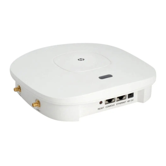
• A power supply port • NOTE: The device also provides a reset button. Figure 17 HP 425 ports (1) 2.4G antenna port 2 (2) 2.4G antenna port 1 (3) 5G antenna port 1 (4) 5G antenna port 2 (5) Reset button... -
Page 21: Weights And Dimensions
Table 1 HP 425 port description Port Standards and protocols Description • IEEE802.1 1b The antenna ports are provided for 2.4 GHz • IEEE802.1 1g 2.4G-1/2 single-RF antennas. • IEEE802.1 1n • IEEE802.1 1a The antenna ports are provided for 5 GHz single-RF 5G-1/2 •... -
Page 22: Power Adapter Specifications
Power adapter specifications Item Description Input 100 VAC to 240 VAC Output +48V @ 0.63 A Storage media and memory specifications Item Description Nor Flash 4 MB Storage media Nand Flash 128 MB Memory DDR2 128 MB... -
Page 23: Appendix B Leds
Appendix B LEDs Table 3 LED description Mark Color Status Description The AP is booting. NOTE: Flashing at 1 Hz When the AP operates as a fit AP, it is Green always in this state before it is registered to an AC. Slowly pulsing A client is connected to the 2.4G port. -
Page 24: Appendix C Built-In Antenna
Appendix C Built-in antenna The HP 425 AP has a built-in dual-band MIMO antenna. Built-in cables connect the MIMO antenna to the 2.4 GHz and 5 GHz antenna ports of the AP. Table 4 Specifications Item Specification Standard IEEE 802.11n and 802.11 a/b/g •... - Page 25 Figure 19 2.4 GHz radiation pattern in the vertical plane Figure 20 5.2 GHz radiation pattern in the horizontal plane...
- Page 26 Figure 21 5.2 GHz radiation pattern in the vertical plane...
-
Page 27: Index
Mounting the AP to a T-rail,8 Chassis views,17 Checking the installation site,1 Power specifications,18 Connecting the AP to the network,13 Connecting the power supply,1 1 Contacting HP,14 Related information,14 Conventions,15 Safety recommendations,1 Installation preparation checklist,3 Storage media and memory specifications,19...