Lexmark C950 Service Manual
Hide thumbs
Also See for C950:
- Service manual (1006 pages) ,
- User manual (275 pages) ,
- Maintenance manual (32 pages)
Table of Contents
Advertisement
Quick Links
Advertisement
Table of Contents

Related Manuals for Lexmark C950


Summary of Contents for Lexmark C950
- Page 1 Revision: January 9, 2014 ™ Lexmark C950 5058-030 • Table of contents • Start diagnostics • Safety and notices • Trademarks • Index Lexmark and Lexmark with diamond design are trademarks of Lexmark International, Inc., registered in the United States and/or other countries.
- Page 2 Lexmark, and Lexmark with diamond design are trademarks of Lexmark International, Inc., registered in the United States and/or other countries. Optra Forms and PrintCryption are trademarks of Lexmark International, Inc.
-
Page 3: Table Of Contents
5058-030 Table of contents Previous Notices and safety information ......... xxiii Printhead LED notice . - Page 4 5058-030 112.02-112.04 LED printhead (C) signal failure ........2-35 Previous 113.01 LED printhead (M) failure .
- Page 5 5058-030 156.01 Toner dispense motor (C) failure ..........2-68 Previous 157.01 Toner dispense motor (M) failure .
- Page 6 5058-030 244.01 Sensor (tray 4 feed out) static jam ......... . 2-114 Previous 244.06 Sensor (tray 4 feed out) late jam .
- Page 7 5058-030 484.01 Sensor (compiler media present) static jam ........2-190 Previous 485.01 Sensor (upper media exit) static jam .
- Page 8 5058-030 No fuse ..............2-243 Previous Color misregistration .
- Page 9 5058-030 EVENT LOG (Diagnostics Menu) ..........3-17 Previous Clear the Event Log .
- Page 10 5058-030 455 staple jam ............. . 3-48 Previous Security Reset Jumper .
- Page 11 5058-030 Stapling one sheet ............3-91 Previous Stapling multiple size media .
- Page 12 5058-030 Sensor (media out) ............3-112 Previous Sensor (media level) .
- Page 13 5058-030 Cover removal procedures ............4-3 Previous Inner cover removal .
- Page 14 5058-030 MPF tray feeder removal ............4-122 Previous Operator panel assembly (SFP) removal .
- Page 15 5058-030 Tray module right cover removal ..........4-211 Previous Tray module top cover removal .
- Page 16 5058-030 Finisher diverter gate removal ........... 4-275 Previous Finisher diverter gate solenoid removal .
- Page 17 5058-030 Stepper motor (entrance/paddle) and belt (entrance/paddle) removal ....4-346 Previous Stepper motor (exit) assembly and belt (exit) removal ....... 4-348 Sub paddle removal .
- Page 18 5058-030 Base machine with add-ons ........... . 5-2 Previous Full configuration .
- Page 19 5058-030 Assembly 10: Cooling fans 3 ............7-11 Previous Assembly 11: Developer 1 .
- Page 20 5058-030 Assembly 69: Finisher—buffer and entrance drive ........7-72 Previous Assembly 70: Finisher—buffer, transport, and upper drive .
- Page 21 5058-030 Previous Next Go Back...
- Page 22 5058-030 Previous Next Go Back Service Manual xxii...
-
Page 23: Notices And Safety Information
5058-030 Notices and safety information Previous The following printhead LED notice labels may be affixed to this printer. Next Printhead LED notice Go Back This product is certified in the U.S. and elsewhere to conform to the requirements of UL 60950-1, Safety of Information Technology Equipment. - Page 24 5058-030 Previous Aviso sobre o printhead LED Este produto está classificado nos EUA e noutros países como estando em conformidade com os requisitos UL 60950-1, Segurança de equipamento destinado a tratamento de informação. A cabeça de impressão LED neste produto consiste num LED de tipo difuso e não excede os níveis correspondentes à Classe I durante o Next funcionamento normal, manutenção ou em condições de assistência recomendada.
- Page 25 5058-030 Previous Aviso de láser Este producto está certificado en los Estados Unidos y otros países para cumplir con las disposiciones de UL 60950-1, que rige la seguridad de los equipos de tecnologías de la información. El cabezal de impresión LED que contiene este producto es de tipo difuso y no supera los niveles de Clase I durante el funcionamiento Next normal, el mantenimiento del usuario ni las condiciones de servicio indicadas.
- Page 26 5058-030 Previous Next Go Back Service Manual xxvi...
-
Page 27: Lithium Warning
5058-030 Previous Lithium warning CAUTION This product contains a lithium battery. THERE IS A RISK OF EXPLOSION IF THE BATTERY Next IS REPLACED BY AN INCORRECT TYPE. Discard used batteries according to the battery manufacturer’s instructions and local regulations. Go Back Safety information The safety of this product is based on testing and approvals of the original design and specific •... - Page 28 5058-030 Previous Sicherheitshinweise • Die Sicherheit dieses Produkts basiert auf Tests und Zulassungen des ursprünglichen Modells und bestimmter Bauteile. Bei Verwendung nicht genehmigter Ersatzteile wird vom Hersteller keine Verantwortung oder Haftung für die Sicherheit übernommen. Next Die Wartungsinformationen für dieses Produkt sind ausschließlich für die Verwendung durch einen •...
- Page 29 5058-030 Previous Informació de Seguretat • La seguretat d'aquest producte es basa en l'avaluació i aprovació del disseny original i els components específics. El fabricant no es fa responsable de les qüestions de Next seguretat si s'utilitzen peces de recanvi no autoritzades. •...
-
Page 30: Preface
5058-030 Preface Previous This manual contains maintenance procedures for service personnel. It is divided into the following chapters: General information contains a general description of the printer and the maintenance approach used to Next repair it. Special tools and test equipment, as well as general environmental and safety instructions, are discussed. -
Page 31: Navigation Buttons
5058-030 Previous Navigation buttons This manual contains navigation buttons in the right margin of each page, making it easier and quicker to navigate. Next Button Description Previous Go Back Click to move the document view backward by one page. Next Click to move the document view forward by one page. -
Page 32: Conventions
5058-030 Previous Conventions Note: A note provides additional information. Warning: A warning identifies something that might damage the product hardware or software. Next There are several types of caution statements: CAUTION Go Back A caution identifies something that might cause a servicer harm. CAUTION This type of caution indicates there is a danger from hazardous voltage in the area of the product where you are working. -
Page 33: General Information
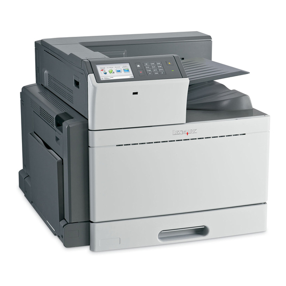
1. General information Previous The Lexmark™ C950 are color SFPs that are are network ready, competitive and easy to use, with brilliant color output and fast print runs. Standard input capacities of these SFPs reach up to 3,660 sheets. Staple and hole punch finisher as well as booklet finishing options are also available. -
Page 34: Printer Specifications
5058-030 Previous Printer specifications Electronics Next ✔ —Supported ✘ Lexmark C950 —Not supported Go Back Processor Speed and type 1.2Ghz Freescale Memory Standard Optional 256MB, 512MB and 1GB Maximum printer memory Hard drive 160GB* Optional Flash memory 256MB Option Slots... -
Page 35: Connectivity (Network Support)
5058-030 Connectivity (network support) Previous ✔ —Supported ✘ —Not supported Lexmark C950 Next Network protocol ✔ 10/100/1000 Base TX Ethernet Go Back ✔ Standard USB2.0 High-speed device port ✔ USB-A host ports (In front/back) Supported file types: .pdf, .gif, .jpeg, .jpg,.bmp, .png, .tiff, .tif, .pcx, .dcx... -
Page 36: Data Streams
5058-030 Data streams Previous ✔ —Supported ✘ —Not supported Lexmark C950 Next Data streams ✔ PostScript 3 Emulation Go Back ✔ PCL 6 Emulation ✔ ✔ PPDS ✔ PDF v1.6 ✔ HTML ✔ Direct Image Dimensions Model Height Width Depth... -
Page 37: Environment Specifications
5058-030 Environment specifications Previous Environment Specifications Operating Air temperature—operating 10.0 to 32.00° C (50 to 90° F) Next Air relative humidity—operating Relative Humidity 15 to 85% Altitude 0–2,500 meters (8,200 ft.) Go Back Atmospheric pressure 760 mmHG, 1,013 HPa Ambient operating environment* 15.6 to 32.2°... -
Page 38: Media Handling
5058-030 Previous Media handling Input and output sources Next Sheet numbers are assuming Lexmark C950 20 lb. xerographic paper Standard input sources Go Back Media trays 520 sheets Multipurpose Feeder 100 sheets capacity Total standard input capacity Duplex Type of duplex... -
Page 39: Media Input Type Specifications
5058-030 Previous ✔ —Supported ✘ —Not supported Next Input source Go Back ✔ ✘ ✔ ✔ ✘ ✔ ✔ ✔ Universal 64-297 mm x 148-432 mm ✘ ✘ ✔ ✘ ✔ ✘ ✘ ✘ 7¾ Envelope (Monarch) 98 x 191 mm ✘... -
Page 40: Finisher
5058-030 Previous ✔ —Supported ✘ —Not supported Next Input type Go Back ✔ ✔ ✔ ✔ ✘ ✘ ✘ ✔ Card stock ✔ ✔ ✔ ✔ ✘ ✘ ✘ ✔ Transparencies ✔ ✔ ✔ ✔ ✘ ✘ ✘ ✔ Labels •... -
Page 41: Supported Finishing Features
5058-030 Supported finishing features Previous Next Go Back Callout Part name Finisher standard bin Finisher Bin 1 Finisher Bin 2 (booklet-maker) Bridge unit Notes: • The finisher shown is the booklet finisher. Bin 2 is available only when the booklet finisher is installed. All paper tray capacities are based on 75-g/m (20-lb) paper. - Page 42 5058-030 Bin 1 Previous • The paper capacity is 3,000 sheets when the standard finisher is installed. The paper capacity is 1,500 sheets when the booklet finisher is installed. • Bin 1 finishing features Next ✔ —Supported ✘ —Not supported Go Back Size ✔...
-
Page 43: Media Guidelines
5058-030 Bin 2 finishing features Previous ✔ —Supported ✘ —Not supported Next Size ✘ ✘ ✘ Executive ✔ ✔ ✔ Go Back Folio ✔ ✔ ✔ JIS B4 ✘ ✘ ✘ JIS B5 ✔ ✔ ✔ Legal ✔ ✔ ✔ Letter (only SEF) ✘... -
Page 44: Unacceptable Paper
5058-030 Grain direction—Grain refers to the alignment of the paper fibers in a sheet of paper. Grain is either grain • Previous long, running the length of the paper, or grain short, running the width of the paper. For 60 to 135 g/m (16 to 36 lb bond) paper, grain long paper is recommended. -
Page 45: Using Recycled Paper And Other Office Papers
As an environmentally conscientious company, Lexmark supports the use of recycled paper produced specifically for use in printhead LED (electrophotographic) printers. While no blanket statement can be made that all recycled paper will feed well, Lexmark consistently tests papers Next that represent recycled cut size copier papers available on the global market. -
Page 46: Tools Required For Service
5058-030 Store individual packages on a flat surface. • Previous • Do not store anything on top of individual paper packages. Tools required for service Next Flat-blade screwdrivers, various sizes #1 Phillips screwdriver, magnetic Go Back #2 Phillips screwdriver, magnetic #2 Phillips screwdriver, magnetic short-blade 7/32 inch (5.5 mm) open-end wrench 7.0 mm nut driver... -
Page 47: Acronyms
Internal Solutions Port Image Transfer Unit Black Liquid Crystal Display LDAP Lightweight Directory Access Protocol Light-Emitting Diode Long-edge Fed Lexmark Embedded Solution LVPS Low Voltage Power Supply Magenta Megabyte Multi-function Printer Multipurpose Feeder Maximum Transmission Unit No Carbon Required Paper... - Page 48 5058-030 Parts Packet Previous PPDS Personal Printer Data Stream Random Access Memory RFID Radio-frequency Identification Raster Imaging Processor Read Only Memory Next Service Engineer Short-edge Fed SMTP Simple Mail Transfer Protocol Go Back SNMP Simple Network Management Protocol Toner Patch Sensing Tandem Tray Module Uniform Resource Locator Universal Serial Bus...
-
Page 49: Diagnostic Information
5058-030 2. Diagnostic information Previous Start Next CAUTION Unplug power cord from the electrical outlet before you connect or disconnect any cable or Go Back electronic board or assembly for personal safety and to prevent damage to the printer. Disconnect any connections between the printer and PCs/peripherals. To determine the corrective action necessary to repair a printer, look for the following information: Does the POR stop? Check •... -
Page 50: Por (Power-On Reset) Sequence
The following is an example of the events that occur during the POR sequence: Turn the machine on. Next The Lexmark splash screen appears with a progress bar in the center until the code is loaded. The scanner exposure lamp flashes several times. The fuser cooling fan turns on. -
Page 51: Error Codes And Messages
5058-030 Previous Error codes and messages User status and attendance messages User primary message Explanation Next Adjusting color Wait for the process to complete. An error has occured Try one or more of the following: Go Back with the Flash Drive. •... - Page 52 5058-030 User status and attendance messages Previous User primary message Explanation Change [paper source] Try one or more of the following: to [paper size] [paper • Touch Use current [paper source] to ignore the message and print from the type] selected tray.
- Page 53 5058-030 User status and attendance messages Previous User primary message Explanation Install bin [x] Try one or more of the following: • Install the specified bin: Next 1.Turn the printer off. 2.Unplug the power cord from the wall outlet. 3.Install the specified bin. 4.Connect the power cord to a properly grounded electrical outlet.
- Page 54 5058-030 User status and attendance messages Previous User primary message Explanation Load Manual Feeder Try one or more of the following: with [size] • Load the specified paper in the multipurpose feeder. Next • Touch Prompt each page, paper loaded to clear the message and continue printing.
- Page 55 5058-030 User status and attendance messages Previous User primary message Explanation 31.xx Missing or Try one or more of the following: defective [color] 1. Remove and reinstall the specified print cartridge. cartridge Next For instructions on removing a print cartridge, touch More Information. 2.
- Page 56 5058-030 User status and attendance messages Previous User primary message Explanation 38 Memory full Try one or more of the following: • Touch Cancel job to clear the message. Next • Install additional printer memory. 39 Complex page, Try one or more of the following: some data may not •...
- Page 57 5058-030 User status and attendance messages Previous User primary message Explanation 56 Parallel port [x] Try one or more of the following: disabled • Touch Continue to clear the message. Next The printer discards any data received through the parallel port. •...
- Page 58 5058-030 User status and attendance messages Previous User primary message Explanation 61 Remove defective Try one or more of the following: disk • Touch Continue to clear the message and continue printing. Next • Install a different printer hard disk before performing any operations that require a printer hard disk.
-
Page 59: Paper Jam Error Codes
5058-030 User status and attendance messages Previous User primary message Explanation 83.xx Transfer module Insert the transfer module into the printer. missing Next 84.xx Replace [color] 1. Replace the photoconductor, following the instruction sheet that came with the photoconductor replacement part. 2. -
Page 60: 1Xx Service Error Codes
5058-030 Previous 1xx service error codes Error code Description Action Next 111.01 LED printhead (K) failure Open circuit detected in the LED Service printhead printhead. error Go to “910.02–910.07 Data Go Back communication error” on page 2-214. 111.02 LED printhead (K) failure Open circuit detected in the LED Service printhead printhead. - Page 61 5058-030 1xx service error codes Previous Error code Description Action 113.04 LED printhead (M) failure Open circuit detected in the LED Service printhead printhead. Next error Go to “113.02-113.04 LED printhead signal failure (M)” on page 2-36. 114.01 LED printhead (Y) failure Open circuit detected in the LED Go Back Service printhead...
- Page 62 5058-030 1xx service error codes Previous Error code Description Action 115.07 Multiple LED printhead read failure Communication failed between the upper Service printhead engine PCBA and more than one LED Next error printhead. Go to “115.07 Multiple LED printhead read failure” on page 2-40.
- Page 63 5058-030 1xx service error codes Previous Error code Description Action 121.01 Encoder pulse fail No change was detected on the speed of Service fuser error the belt for more than 1 second. Next Go to “121.01 Encoder pulse failure” on page 2-46.
- Page 64 5058-030 1xx service error codes Previous Error code Description Action 121.13 Fuser thermostat failure The Fuser Assembly Thermostat is Service fuser error broken. Next Go to “121.13 Fuser thermostat failure” on page 2-51. 126.01 Fuser interface failure There is a a broken link between upper Go Back Service fuser error engine PCBA and the fuser.
- Page 65 5058-030 1xx service error codes Previous Error code Description Action 132.03 ATC sensor(M) failure There is an error at the ATC sensor. Service engine error Go to “132.03 ATC sensor (M) failure” Next on page 2-58. 132.04 ATC sensor(C) failure There is an error at the ATC sensor.
- Page 66 5058-030 1xx service error codes Previous Error code Description Action 156.01 Toner dispense motor (C) failure The toner dispense motor is not Service engine error functioning. Next Go to “156.01 Toner dispense motor (C) failure” on page 2-68. 157.01 Toner dispense motor (M) failure The toner dispense motor is not Go Back Service engine error...
- Page 67 5058-030 1xx service error codes Previous Error code Description Action 175.07 Rear upper center cooling fan failure The rear upper center cooling fan is not Service engine error functioning. Next Go to “175.07 Fuser driver PCBA cooling fan failure” on page 2-73.
-
Page 68: 2Xx Service Error Codes
5058-030 1xx service error codes Previous Error code Description Action 191.17 Lower engine PCBA fuse 13 blown A fuse has blown. Service engine error Go to “191.17 Lower engine PCBA fuse Next 13 blown” on page 2-79. 191.18 Upper engine PCBA data failure Data values are not normal on the upper Service engine error engine memory. - Page 69 5058-030 2xx service error codes Previous Error code Description Action 200.05 Sensor (registration) lag jam The media reached the sensor Paper jam (registration) but did not clear it within the Next specified time. Go to “200.05/200.55 Sensor (registration) lag jam” on page 2-85.
- Page 70 5058-030 2xx service error codes Previous Error code Description Action 203.03 Sensor (upper redrive) late jam The media is late reaching the sensor Paper jam (upper redrive) within the specified time Next after reaching the sensor (fuser exit). Go to “203.03 Sensor (upper redrive) late jam”...
- Page 71 5058-030 2xx service error codes Previous Error code Description Action 243.03 Sensor (tray 3 feed out) late jam The media is late reaching the sensor (tray Paper jam 3 feed out) within the specified time after Next the feed from tray 4 has started. Go to “243.03/243.06 Sensor (tray 3 feed out) late jam”...
-
Page 72: 3Xx Service Errors
5058-030 2xx service error codes Previous Error code Description Action 250.05 Sensor (MPF feed out) lag jam The media reached the sensor (MPF feed Paper jam out) but did not clear it within the specified Next time. Go to “250.05 Sensor (MPF feed out) lag jam”... - Page 73 5058-030 3xx service errors Previous Error code Description Action 381.03 Sensor (rear tamper HP) late error The sensor (rear tamper HP) did not Service finisher error activate within the specified time. Next Go to “381.03 Sensor (rear tamper HP) late jam” on page 2-138.
- Page 74 5058-030 3xx service errors Previous Error code Description Action 381.13 Sensor (stacker bin upper limit) error The media level exceeds the height that is Service finisher error allowed by the sensor (stacker upper limit). Next Go to “381.13 Sensor (stacker bin upper limit) error”...
- Page 75 5058-030 3xx service errors Previous Error code Description Action 381.22 Sensor (punch carriage shift HP) late The sensor (punch carriage shift HP) didn’t Service finisher error error activate within the specified time. Next Go to “381.18 Sensor (punch carriage shift HP) late jam” on page 2-157.
- Page 76 5058-030 3xx service errors Previous Error code Description Action 381.34 Sensor (booklet rear tamper HP) lag The sensor (booklet rear tamper HP) Service finisher error error activated, but did not clear within the Next specified time. Go to “381.34 Sensor (booklet rear tamper HP) lag jam”...
-
Page 77: 4Xx Service Error Codes
5058-030 Previous 4xx service error codes Error code Description Action Next 401.01 Sensor (finisher media entrance) static Media remains detected by the sensor Service finisher error jam. (finisher media entrance). Go to “401.01 Sensor (finisher media Go Back entrance) static jam” on page 2-177. - Page 78 5058-030 4xx service error codes Previous Error code Description Action 483.03 Sensor (buffer path) late jam The media is late reaching the sensor Service finisher error (diverter gate) within the specified time. Next Go to “483.03 Sensor (buffer path) late jam”...
-
Page 79: 8Xx Service Error Codes
5058-030 4xx service error codes Previous Error code Description Action 491.05 Sensor (booklet media entrance) lag The sensor (booklet media entrance) Service finisher error activated, but did not clear within the Next specified time. Go to “491.05 Sensor (booklet media entrance) lag jam”... - Page 80 5058-030 9xx service error codes Previous Error code Description Action 910.03 Data communication error Firmware upgrade is needed. Service data error Go to “910.02–910.07 Data Next communication error” on page 2-214. 910.04 Data communication error Firmware upgrade is needed. Service data error Go Back Go to “910.02–910.07 Data...
- Page 81 5058-030 9xx service error codes Previous Error code Description Action 956.00 RIP card assembly processor failure The RIP card processor has failed. Service system board Go to “956.00 RIP card assembly Next error processor failure” on page 2-217. 956.01 RIP card assembly processor over The RIP card assembly has exceeded safe Service system board temperature failure...
-
Page 82: Service Checks
5058-030 Previous Service checks 111.01 LED printhead (K) failure Next Step Action and questions Check the LED Printhead (K) for Go to step 2. Install the LED Printhead (K) proper installation. properly. Go Back Is the LED Printhead (K) properly installed? Check the event log for the Go to step Replace the LED Printhead (K). -
Page 83: 112.04 Led Printhead (C) Signal Failure
5058-030 Previous Step Action and questions Check the event log for the Go to step Replace the LED Printhead (C). “112.02-112.04 LED history of errors that occurred printhead (C) signal failure” on Go to “LED printhead removal” page 2-35. 1. Enter the Diagnostics Menu. on page 4-96. -
Page 84: 113.04 Led Printhead Signal Failure (M)
5058-030 113.02-113.04 LED printhead signal failure (M) Previous Step Action and questions Check the LED printhead. Go to step 2. Replace the connections. Replace the printhead flat data Next cable. Is the above component properly connected? Go Back Replace the LED printhead. Go to step 3. -
Page 85: Multiple Led Printhead Power Supply Failure
5058-030 Previous Step Action and questions Replace the LED printhead. Go to step 3. Problem resolved Go to “LED printhead removal” on page 4-96. Next Does the error remain? Replace the printhead interface Go to step 4. Problem resolved Go Back contact. -
Page 86: Multiple Led Printhead Download Failure
5058-030 Previous Step Action and questions Replace the printhead flat data Go to step 3. Problem resolved cable assembly. Does the error remain? Next Replace the printhead interface Go to step 4. Problem resolved contact. Go Back Does the error remain? POR the machine. -
Page 87: Single Led Printhead Download Failure
5058-030 115.04 Single LED printhead download failure Previous Step Action and questions Check the LED printhead for Go to step 2. Replace the connections. proper connections. Next Is the above component properly connected? Go Back Replace the LED printhead. Go to Go to step 3. -
Page 88: Single Led Printhead Mismatch Failure
5058-030 115.06 Single LED printhead mismatch failure Previous Step Action and questions Check the LED printhead. Check the LED printhead Install with the correct LED installation and connections. printhead. Go to “LED printhead Next removal” on page 4-105. Is the correct LED printhead installed? Go Back 115.07 Multiple LED printhead read failure... -
Page 89: Multiple Led Printhead Write Failure
5058-030 Previous Step Action and questions POR the machine. Replace the lower engine PCBA . Problem resolved Go to “Lower engine PCBA Does the error continue? removal” on page 4-98. Next Go to step 5. POR the machine. Replace the upper printer engine Problem resolved PCBA. -
Page 90: Multiple Led Printhead Communication Failure
5058-030 Previous Step Action and questions Replace the printhead interface Go to step 5. Problem resolved contact. Does the error remain? Next Check the PC/developer drive Go to step 6. Replace connections and motor assembly. re-install the PC/developer drive motor assembly. Go Back Is the above component properly installed? -
Page 91: Single Led Printhead Communication Failure
5058-030 115.12 Single LED printhead communication failure Previous Step Action and questions Check the LED printhead for Go to step 2. Install the LED printhead proper installation. properly. Next Is the LED Printhead properly installed? Go Back Check the LED printhead for Replace the LED printhead. -
Page 92: Single Led Printhead Clock Failure
5058-030 Previous Step Action and questions POR the machine. Replace the lower engine PCBA. Problem resolved Go to “Lower engine PCBA Does the error continue? removal” on page 4-98. Next Go to step 4. POR the machine. Replace the upper printer engine Problem resolved PCBA. -
Page 93: Fuser Motor Failure
5058-030 Previous Step Action and questions Replace the tray module Go to step 3. Problem resolved controller PCBA. Go to “Tray module controller PCBA removal” on page 4-206. Next Does the error remain? POR the machine. Replace the lower engine PCBA. Problem resolved Go Back Go to... -
Page 94: Fuser Pressure Roll Retract Motor Failure
5058-030 120.02 Fuser pressure roll retract motor failure Previous Step Action and questions Check the fuser pressure roll Go to step 2. Replace the connections. retract motor. Next Is the above component properly connected? Go Back Replace the fuser pressure roll Go to step 3. -
Page 95: Heat Belt (Center) Disconnection Error
5058-030 121.02 Encoder pulse failure Previous Step Action and questions Check the fuser assembly. Go to step 2. Replace the connections. Next Is the above component properly connected? Go Back Replace the fuser assembly. Go Go to step 3. Problem resolved “Fuser assembly removal”... -
Page 96: Heat Belt (Rear) Disconnection Error
5058-030 Previous Step Action and questions POR the machine. Replace the upper printer engine Problem resolved PCBA. Go to Does the error continue? “Upper printer engine PCBA removal” on page 4-181. Next 121.05 Heat belt (rear) disconnection error Go Back Step Action and questions Check the fuser assembly. -
Page 97: Heat Belt (Center) Temperature Increase Failure
5058-030 121.07 Heat belt (center) temperature increase failure Previous Step Action and questions Check the fuser assembly. Go to step 2. Remove foreign particles, and replace the connections. Next Is the above component properly connected? Go Back Replace the fuser assembly. Go Go to step 3. -
Page 98: Heat Belt Rotation Failure
5058-030 Previous Step Action and questions POR the machine. Replace the upper printer engine Problem resolved PCBA. Go to Does the error continue? “Upper printer engine PCBA removal” on page 4-181. Next 121.10 Heat belt rotation failure Go Back Step Action and questions Check the fuser assembly. -
Page 99: Fuser Failure
5058-030 121.12 Fuser failure Previous Step Action and questions POR the machine. Go to step 2. Problem resolved Next Does the error continue? Replace the fuser assembly. Go Replace the fuser drive PCBA. Problem resolved Go Back Go to “Fuser assembly removal” “Fuser driver PCBA on page 4-78. -
Page 100: Fuser Driver To Upper Engine Pcba Interface Failure
5058-030 126.02 Fuser driver to upper engine PCBA interface failure Previous Step Action and questions Check the fuser driver PCBA. Go to step 2. Replace the connections. Next Is the above component properly connected? Go Back POR the machine. Go to step 3. Problem resolved Does the error continue? Replace the upper printer engine... -
Page 101: Fuser Driver High Voltage Error
5058-030 Previous Step Action and questions Replace the fuser driver PCBA. Go to step 3. Problem resolved Go to “Fuser driver PCBA removal” on page 4-84. Next Does the error remain? POR the machine. Replace the upper printer engine Problem resolved PCBA. -
Page 102: Igbt High Temperature Error
5058-030 126.08 IGBT high temperature error Previous Step Action and questions Check the fuser driver PCBA. Go to step 2. Replace the connections. Next Is the above component properly connected? Go Back Replace the fuser driver PCBA. Go to step 3. Problem resolved Go to “Fuser driver PCBA... -
Page 103: Atc Sensor (K) Failure
5058-030 Previous Step Action and questions Replace the fuser assembly. Go Go to step 4. Problem resolved “Fuser assembly removal” on page 4-78. Next Does the error remain? POR the machine. Replace the upper printer engine Problem resolved PCBA. Go Back Go to Does the error continue? “Upper printer engine... -
Page 104: Atc Sensor (Y) Failure
5058-030 Previous Step Action and questions Check the developer motor for Go to step 8. Go to step 7. proper operation. When performing motor tests, ensure Next that all cover and door interlock switches are overridden. Go Back 1. Enter the Diagnostics Menu. 2. - Page 105 5058-030 Previous Step Action and questions Check the toner dispense motor Go to step 6. Go to step 5. for proper operation. When performing motor tests, ensure Next that all cover and door interlock switches are overridden. Go Back 1. Enter the Diagnostics Menu. 2.
-
Page 106: Atc Sensor (M) Failure
5058-030 132.03 ATC sensor (M) failure Previous Step Action and questions Check the path from the toner Go to step 2. Remove the toner blockages, cartridge to the developer. including internal clogs inside the Next developer and toner cartridge. Is the above component free from obstacles? Go Back Check the ATC sensor PCB. -
Page 107: Atc Sensor (C) Failure
5058-030 Previous Step Action and questions Check the developer motor for Replace the PC/developer drive Replace the connection. proper connection. motor. Go to “PC/developer drive Is the above component motor removal” on page 4-132. Next properly connected? POR the machine. Replace the lower engine PCBA. -
Page 108: Upper Printer Engine Pcba Communication Error
5058-030 Previous Step Action and questions Check the toner dispense motor Replace the toner dispense Replace the connections. for proper connection. motor. Go to “Toner dispense motor Is the above component removal” on page 4-163. Next properly connected? Check the developer motor for Go to step 8. -
Page 109: Registration Drive Motor Failure
5058-030 140.01 Registration drive motor failure Previous Step Action and questions Check the registration drive Go to step 3. Go to step 2. motor for proper operation. Next When performing motor tests, ensure that all cover and Go Back door interlock switches are overridden. -
Page 110: Drum Drive Motor (Y/M/C) Failure
5058-030 Previous Step Action and questions Check the drum motor for proper Replace the PC/developer drive Replace the connections. connection. motor. Go to “PC/developer drive motor removal” on page 4-132. Is the above component Next properly connected? POR the machine. Replace the lower engine PCBA. -
Page 111: Tray 1 Lift Motor Failure
5058-030 146.xx Tray 1 lift motor failure Previous Step Action and questions Check the sensor (tray 1 media Go to step 2. Reattach the sensor. level) on the tray 1 media feeder. Next Is the sensor properly Go Back attached? Check the sensor for proper Go to step 4. -
Page 112: Transfer Belt Motor Failure
5058-030 151.01 Transfer belt motor failure Previous Step Action and questions Check the transfer belt motor for Go to step 3. Go to step 2. proper operation. Next When performing motor tests, ensure that all cover and Go Back door interlock switches are overridden. -
Page 113: Second Transfer Contact/Retract Failure
5058-030 Previous Step Action and questions Check the sensor (1st transfer Replace the 1st transfer retract Replace the connections. rolls retract HP) for proper clutch assembly. connection. Go to “1st transfer retract clutch assembly removal” on Next Is the above component page 4-22. -
Page 114: Developer (Y/M/C) Motor Failure
5058-030 Previous Step Action and questions Check the sensor (2nd transfer Replace the printer left duplex Replace the connections. roll retract HP) for proper door assembly. Go to “Printer connection. left duplex door assembly removal” on page 4-136. Next Is the above component properly connected? Check the 2nd transfer roller Go to step 5. -
Page 115: Toner Dispense Motor (K) Failure
5058-030 Previous Step Action and questions Check the developer motor for Replace the PC/developer drive Replace the connections. proper connection. motor. Go to “PC/developer drive motor removal” on page 4-132. Is the above component Next properly connected? POR the machine. Replace the lower engine PCBA. -
Page 116: Toner Dispense Motor (C) Failure
5058-030 156.01 Toner dispense motor (C) failure Previous Step Action and questions Replace the toner cartridge. Go to step 2. Problem resolved Next Does the error remain? Check the toner smart chip PCB. Go to step 3. Replace the connections. Go Back Is the above component properly connected? -
Page 117: Toner Dispense Motor (Y) Failure
5058-030 Previous Step Action and questions Check the toner dispense motor Go to step 5. Go to step 4. for proper operation. When performing motor tests, ensure Next that all cover and door interlock switches are overridden. Go Back 1. Enter the Diagnostics Menu. 2. -
Page 118: Fuser Cooling Fan Failure
5058-030 Previous Step Action and questions Check the toner dispense motor Go to step 5. Go to step 4. for proper operation. When performing motor tests, ensure Next that all cover and door interlock switches are overridden. Go Back 1. Enter the Diagnostics Menu. 2. -
Page 119: Front Upper Cooling Fan Failure
5058-030 172.01 Front upper cooling fan failure Previous Step Action and questions Check the front upper cooling fan. Go to step 2. Replace the connections. Next Is the above component properly connected? Go Back Replace the front upper cooling Go to step 3. Problem resolved fan. -
Page 120: Front Right Cooling Fan Failure
5058-030 175.01 Front right cooling fan failure Previous Step Action and questions Check the front right cooling fan. Go to step 2. Replace the connections. Next Is the above component properly connected? Go Back Replace the front right cooling Go to step 3. Problem resolved fan. -
Page 121: Suction Fan Failure
5058-030 Previous Step Action and questions POR the machine. Replace the upper printer engine Problem resolved PCBA. Go to Does the error continue? “Upper printer engine PCBA removal” on page 4-181. Next 175.05 Suction fan failure Go Back Step Action and questions Check the suction fan. -
Page 122: Upper Exhaust Cooling Fan Failure
5058-030 Previous Step Action and questions Replace the fuser driver PCBA Go to step 3. Problem resolved cooling fan. Does the error continue? Next POR the machine. Replace the lower engine PCBA. Problem resolved Go to “Lower engine PCBA Go Back Does the error continue? removal”... -
Page 123: Lower Engine Pcba Fuse 2 Blown
5058-030 Previous Step Action and questions POR the machine. Replace the upper printer engine Problem resolved PCBA. Go to Does the error continue? “Upper printer engine PCBA removal” on page 4-181. Next 191.06 Lower engine PCBA fuse 2 blown Go Back Step Action and questions Warning: Remove the cause of... -
Page 124: Lower Engine Pcba Fuse 4 Blown
5058-030 191.08 Lower engine PCBA fuse 4 blown Previous Step Action and questions Warning: Remove the cause of Go to step 2. Replace the faulty parts, or repair blown fuse before replacing the the circuits. Next lower engine PCBA. Check the following parts circuits for overcurrent and overvoltage: Go Back •... -
Page 125: Lower Engine Pcba Fuse 7 Blown
5058-030 Previous Step Action and questions POR the machine. Replace the lower engine PCBA. Problem resolved Go to “Lower engine PCBA Does the error continue? removal” on page 4-98. Next 191.11 Lower engine PCBA fuse 7 blown Go Back Step Action and questions Warning: Remove the cause of Go to step 2. -
Page 126: Lower Engine Pcba Fuse 9 Blown
5058-030 191.13 Lower engine PCBA fuse 9 blown Previous Step Action and questions Warning: Remove the cause of Go to step 2. Replace the faulty parts, or repair blown fuse before replacing the the circuits. Next lower engine PCBA. Check the toner dispense motor (Y, M, C, K) for overcurrent and Go Back overvoltage. -
Page 127: Lower Engine Pcba Fuse 12 Blown
5058-030 191.16 Lower engine PCBA fuse 12 blown Previous Step Action and questions Warning: Remove the cause of Go to step 2. Replace the faulty parts, or repair blown fuse before replacing the the circuits. Next lower engine PCBA. Check the following parts circuits for overcurrent and overvoltage: Go Back •... -
Page 128: Upper Engine Pcba Access Failure
5058-030 191.19 Upper engine PCBA access failure Previous Step Action and questions POR The machine. Go to step 2 Problem resolved Next Does the error continue? Turn the power OFF and check Turn the power OFF, and replace Problem resolved Go Back whether there is poor connection the upper printer engine... -
Page 129: Lower Engine Pcba Fuse 15 Blown
5058-030 191.24 Lower engine PCBA fuse 15 blown Previous Step Action and questions Warning: Remove the cause of Go to step 2 Replace the faulty parts, or repair blown fuse before replacing the the circuits. Next lower engine PCBA. Check the upper redrive assembly circuits for overcurrent Go Back and overvoltage:... -
Page 130: Sensor (Registration) Late Jam (Feeding From The Tray)
5058-030 Previous Step Action and questions Check the sensor (registration) Replace the registration/transport Replace the connections. for proper connection. roll assembly. Go to “Registration/transport roller assembly removal” on Is the above component Next page 4-143 properly connected? Check the registration/transport Go to step 5. - Page 131 5058-030 Previous Step Action and questions Check the registration drive Go to step 6. Go to step 5. motor for proper operation. When performing motor tests, ensure Next that all cover and door interlock switches are overridden. Go Back 1. Enter the Diagnostics Menu. 2.
-
Page 132: Sensor (Registration) Late Jam (Feeding From The Mpf)
5058-030 Previous Step Action and questions POR the machine, and perform a Replace the upper printer engine Problem resolved PRINT test. PCBA. Go to Go to “PRINT TESTS” on “Upper printer engine page 3-22. PCBA removal” on page 4-181. Next Does the error continue? Go Back 200.03 Sensor (registration) late jam (feeding from the MPF) -
Page 133: 200.55 Sensor (Registration) Lag Jam
5058-030 Previous Step Action and questions Check the media transport/MPF Go to step 8. Go to step 7. drive motor for proper operation. When performing motor tests, ensure Next that all cover and door interlock switches are overridden. Go Back 1. - Page 134 5058-030 Previous Step Action and questions Check the 2nd transfer roller. Go to step 4. Clean or replace the 2nd transfer roller. Go to Is the above component free of “2nd transfer roller excess wear and removal” on page 4-24. Next contamination? Check the sensor (registration)
-
Page 135: Sensor (Registration) Late Jam (80K Interval Exceeded For Feed Rollers)
5058-030 Previous Step Action and questions Check the Media Transport/MPF Go to step 10. Go to step 9. drive motor assembly for proper operation. When performing Next motor tests, ensure that all cover and door interlock switches are Go Back overridden. - Page 136 5058-030 Previous Step Action and questions Check the sensor (registration) Replace the media transport/MPF Replace the connections. for proper connection. drive motor. Go to “Media transport/MPF Is the above component drive motor removal” on Next properly connected? page 4-118. Check the registration drive motor Go to step 7.
- Page 137 5058-030 Previous Step Action and questions Check the media transport/MPF Go to step 11. Go to step 10. drive motor for proper operation. When performing motor tests, ensure Next that all cover and door interlock switches are overridden. Go Back 1.
-
Page 138: Sensor (Registration) Lag Jam
5058-030 Previous Step Action and questions Check the tray module lower Go to step 7. Go to step 6. transport motor for proper operation. When performing Next motor tests, ensure that all cover and door interlock switches are Go Back overridden. -
Page 139: Sensor (Media On Belt) Late Jam
5058-030 Previous Step Action and questions Check the sensor (media on belt) Replace the sensor (media on Replace the connection. for proper connection. belt). Go to “Sensor (media on belt) Is the above component removal” on page 4-149. Next properly connected? Perform a print test. - Page 140 5058-030 Previous Step Action and questions Check the registration drive Replace the registration drive Replace the connection. motor for proper connection. motor. Go to “Registration drive motor Is the above component removal” on page 4-141. Next properly connected? Check the 2nd transfer roller Go to step 8.
-
Page 141: Sensor (Fuser Exit) Static Jam
5058-030 Previous Step Action and questions Check the registration clutch for Go to step 12. Go to step 11. proper operation. When performing motor tests, ensure Next that all cover and door interlock switches are overridden. Go Back 1. Enter the Diagnostics Menu. 2. -
Page 142: Exit Sensor 1 Late Jam
5058-030 Previous Step Action and questions Perform a print test. Go to Replace the upper printer engine Problem resolved PCBA. “PRINT TESTS” on page 3-22. Go to “Upper printer engine Does the error continue? PCBA removal” on page 4-181. Next 202.03 Exit Sensor 1 Late Jam Go Back Step... - Page 143 5058-030 Previous Step Action and questions Check the 2nd transfer roller Go to step 8. Go to step 7. retract motor for proper operation. When performing Next motor tests, ensure that all cover and door interlock switches are Go Back overridden.
- Page 144 5058-030 Previous Step Action and questions Check the media transport/MPF Go to step 12. Go to step 11. drive motor assembly for proper operation. When performing Next motor tests, ensure that all cover and door interlock switches are Go Back overridden.
-
Page 145: 202.05 Sensor (Fuser Exit) Lag Jam
5058-030 202.04/202.05 Sensor (fuser exit) lag jam Previous Step Action and questions Check the media path. Go to step 2. Remove any media or media fragments. Next Is the media path free of any media fragments? Go Back Check the sensor (fuser exit) for Go to step 2. -
Page 146: Sensor (Fuser Exit) Lag Jam
5058-030 Previous Step Action and questions Check the lower redrive shift Go to step 8. Go to step 7. motor assembly for proper operation. When performing Next motor tests, ensure that all cover and door interlock switches are Go Back overridden. -
Page 147: Sensor (Upper Redrive) Static Jam
5058-030 “202.04/202.05 Sensor (fuser exit) lag jam” on page 2-97. Previous 203.01 Sensor (upper redrive) static jam Step Action and questions Next Check the media path. Go to step 2. Remove any media or media fragments. Go Back Is the media path free of any media fragments? Check the sensor (upper redrive) Go to step 4. - Page 148 5058-030 Previous Step Action and questions Check the upper redrive rolls for Go to step 3. Replace the upper redrive wear. assembly. Go to “Upper redrive assembly Is the above component free of removal” on page 4-183. Next excess wear and damage? Check the sensor (upper redrive) Go to step 5.
-
Page 149: Sensor (Upper Redrive) Lag Jam
5058-030 Previous Step Action and questions Check the upper redrive diverter Go to step 9. Go to step 8. gate for proper operation. When performing motor tests, ensure Next that all cover and door interlock switches are overridden. Go Back 1. - Page 150 5058-030 Previous Step Action and questions Check the sensor (upper redrive) Go to step 5. Go to step 4. for proper operation. 1. Enter the Diagnostics Menu. 2. Touch SENSOR TESTS. Next 3. Touch PRINTER SENSOR TESTS. 4. Touch Sensor (upper Go Back redrive).
-
Page 151: Sensor (Duplex Wait) Static Jam
5058-030 230.01 Sensor (duplex wait) static jam Previous Step Action and questions Check the media path. Go to step 2. Remove any media or media fragments. Next Is the media path free of any media fragments? Go Back Check the sensor (duplex wait) Go to step 4. - Page 152 5058-030 Previous Step Action and questions Check the sensor (duplex wait ) Go to step 4. Go to step 3. for proper operation. 1. Enter the Diagnostics Menu. 2. Touch SENSOR TESTS. Next 3. Touch PRINTER SENSOR TESTS. 4. Touch Sensor (duplex wait). Go Back Does the display on the operator panel change every...
- Page 153 5058-030 Previous Step Action and questions Check upper redrive motor for Go to step 9. Go to 8. proper operation. When performing motor tests, ensure Next that all cover and door interlock switches are overridden. Go Back 1. Enter the Diagnostics Menu. 2.
- Page 154 5058-030 232.03 Sensor (registration) late jam (duplex direct) Previous Step Action and questions Check the media path. Go to step 2. Remove any media or media fragments. Next Is the media path free of any media fragments? Go Back Check the duplex rolls for wear. Go to step 3.
-
Page 155: Sensor (Tray 2 Feed Out) Static Jam
5058-030 Previous Step Action and questions POR the machine, and perform a Replace the upper printer engine Problem resolved print test. Go to PCBA. “PRINT TESTS” on page 3-22. Go to “Upper printer engine PCBA removal” on page 4-181. Next Does the error continue? 242.01 Sensor (tray 2 feed out) static jam Go Back... -
Page 156: 242.06 Sensor (Tray 2 Feed Out) Late Jam
5058-030 242.03/242.06 Sensor (tray 2 feed out) late jam Previous Step Action and questions Check the media path. Go to step 2. Remove any media or media fragments. Next Is the media path free of any media fragments? Go Back Check the pick rollers for wear. -
Page 157: Sensor (Tray 2 Feed Out) Late Jam
5058-030 Previous Step Action and questions Check the tray module upper Replace the tray module upper Replace the connections. transport motor for proper transport motor. Go to “Tray connection. module upper transport motor removal” on page 4-214. Next Is the above component properly connected? POR the machine, and perform a Replace the lower engine PCBA. -
Page 158: Sensor (Tray 3 Feed Out) Static Jam
5058-030 Previous Step Action and questions Check the sensor (tray 2 feed Clean or replace the sensor (tray Replace the connection. out) for proper connection. 2 feed out). Go to “Sensor (tray module feedout) removal” on page 4-200. Is the above component Next properly connected? Check the tray module upper... -
Page 159: 243.06 Sensor (Tray 3 Feed Out) Late Jam
5058-030 Previous Step Action and questions Check the sensor (tray 3 feed Go to step 4. Go to step 3. out) for proper operation. 1. Enter the Diagnostics Menu. 2. Touch SENSOR TESTS. Next 3. Touch PRINTER SENSOR TESTS. 4. Touch Sensor (tray 3 feed Go Back out). - Page 160 5058-030 Previous Step Action and questions Check the sensor (tray 3 feed Go to step 6. Go to step 5. out) for proper operation. 1. Enter the Diagnostics Menu. 2. Touch SENSOR TESTS. Next 3. Touch PRINTER SENSOR TESTS. 4. Touch Sensor (tray 3 feed Go Back out).
-
Page 161: Sensor (Tray 3 Feed Out) Late Jam
5058-030 Previous Step Action and questions POR the machine, and perform a Replace the upper printer engine Problem resolved print test. Go to PCBA. “PRINT TESTS” on page 3-22. Go to “Upper printer engine PCBA removal” on page 4-181. Next Does the error continue? 243.06 Sensor (tray 3 feed out) late jam Go Back... -
Page 162: Sensor (Tray 4 Feed Out) Static Jam
5058-030 Previous Step Action and questions Check the tray module upper Go to step 8. Go to step 7. transport motor for proper operation. When performing Next motor tests, ensure that all cover and door interlock switches are Go Back overridden. -
Page 163: Sensor (Tray 4 Feed Out) Late Jam
5058-030 Previous Step Action and questions Check the sensor (tray 4 feed Go to step 4. Go to step 3. out) for proper operation. 1. Enter the Diagnostics Menu. 2. Touch SENSOR TESTS. Next 3. Touch PRINTER SENSOR TESTS. 4. Touch Sensor (tray 4 feed Go Back out). - Page 164 5058-030 Previous Step Action and questions Check the sensor (tray 4 feed Go to step 6. Go to step 5. out) for proper operation. 1. Enter the Diagnostics Menu. 2. Touch SENSOR TESTS. Next 3. Touch PRINTER SENSOR TESTS. 4. Touch Sensor (tray 4 feed Go Back out).
-
Page 165: Sensor (Tray 4 Feed Out) Late Jam (80K Interval Exceeded For Feed Rolls)
5058-030 Previous Step Action and questions Check the tray module upper Go to step 10. Go to step 9. transport motor for proper operation. When performing Next motor tests, ensure that all cover and door interlock switches are Go Back overridden. - Page 166 5058-030 Previous Step Action and questions Check the transport rollers for Go to step 4. Replace the transport rollers. wear. Go to “Tray module transport rollers removal” on page 4-213. Is the above component free of Next excess wear and damage? Check the sensor (tray 4 feed Go to step 6.
-
Page 167: Sensor (Tray 5 Feed Out) Static Jam
5058-030 Previous Step Action and questions Check the tray module upper Go to step 10. Go to step 9. transport motor for proper operation. When performing Next motor tests, ensure that all cover and door interlock switches are Go Back overridden. -
Page 168: Sensor (Tray 5 Feed Out) Late Jam
5058-030 Previous Step Action and questions Check the connection between Replace the tray module Replace the connections. the lower engine PCBA and the controller PCBA. tray module controller PCBA. Go to “HCF controller card PCBA removal” on page 4-432. Next Are the above components Go to step 4. -
Page 169: Sensor (Tray 5 Feed Out) Lag Jam
5058-030 Previous Step Action and questions Check the HCF feed lift motor for Replace the HCF feed lift motor. Replace the connections. proper connection. Go to “HCF feed lift motor removal” on page 4-433. Is the above component Next properly connected? Check the HCF transport motor Go to step 9. -
Page 170: Sensor (Tray 5 Feed Out) Late Jam (80K Interval Exceeded For Feed Rolls)
5058-030 Previous Step Action and questions Check the sensor (tray 5 feed Clean or replace the sensor (tray Replace the connection. out) for proper connection. 5 feed out). Go to “HCF sensor (tray 5 feedout) removal” on page 4-446. Is the above component Next properly connected? Check the HCF transport motor... - Page 171 5058-030 Previous Step Action and questions Check the transport rollers for Go to step 4. Replace the transport rollers. wear. Go to “HCF transport roller kit removal” on page 4-452. Is the above component free of Next excess wear and damage? Check the sensor (tray 5 feed Clean or replace the sensor (tray Replace the connection.
-
Page 172: Sensor (Hcf Feed Out) Late Jam
5058-030 Previous Step Action and questions Check the the HCF controller Replace the HCF controller card Replace the connections. card PCBA for proper connection. PCBA. Go to “HCF controller card PCBA removal” on page 4-432. Is the above component Next Go to step 10. -
Page 173: Sensor (Mpf Feed Out) Lag Jam
5058-030 Previous Step Action and questions Check the HCF feed lift motor for Replace the HCF feed lift motor. Replace the connections. proper connection. Go to “HCF feed lift motor removal” on page 4-360. Is the above component Next properly connected? Check the HCF transport motor Go to step 9. - Page 174 5058-030 Previous Step Action and questions Check the sensor (MPF feed out) Go to step 5. Go to step 4. for proper operation. 1. Enter the Diagnostics Menu. 2. Touch SENSOR TESTS. Next 3. Touch PRINTER SENSOR TESTS. 4. Touch Sensor (MPF feed Go Back out).
- Page 175 5058-030 Previous Step Action and questions Check the 2nd transfer roller Go to step 9. Go to step 8. retract motor for proper operation. When performing Next motor tests, ensure that all cover and door interlock switches are Go Back overridden.
- Page 176 5058-030 Previous Step Action and questions Check the media transport/MPF Go to step 13. Go to step 12. drive motor assembly for proper operation. When performing Next motor tests, ensure that all cover and door interlock switches are Go Back overridden.
-
Page 177: Sensor (Mpf Feed Out) Late Jam
5058-030 250.06 Sensor (MPF feed out) late jam Previous Step Action and questions Check the media path. Go to step 2. Remove any media or media fragments. Next Is the media path free of any media fragments? Go Back Check the MPF rollers for wear. Go to step 3. -
Page 178: Sensor (Mpf Feed Out) Late Jam (80K Interval Exceeded For Feed Rolls)
5058-030 Previous Step Action and questions Print a sample page using the Replace the lower engine PCBA. Problem resolved MPF. Go to “Lower engine PCBA removal” on page 4-98. Does the error continue? Next Print a sample page using the Replace the upper printer engine Problem resolved MPF. -
Page 179: Sensor (Front Tamper Hp) Late Jam
5058-030 Previous Step Action and questions Check the MPF feed/lift motor for Go to step 7. Go to step 6. proper operation. When performing motor tests, ensure Next that all cover and door interlock switches are overridden. Go Back 1. Enter the Diagnostics Menu. 2. - Page 180 5058-030 Previous Step Action and questions Check the sensor (front tamper Go to step 3. Go to step 2. HP) for proper operation. 1. Enter the Diagnostics Menu. 2. Touch SENSOR TESTS. Next 3. Touch FINISHER SENSOR TESTS. 4. Touch Sensor (front tamper Go Back HP).
-
Page 181: Tray 2 Lift Motor Failure
5058-030 324.xx Tray 2 lift motor failure Previous Step Action and questions Check the sensor (tray 2 media Go to step 2. Reattach the sensor. level) on the tray 2 media feeder. Next Is the sensor properly Go Back attached? Check the sensor for proper Go to step 4. -
Page 182: Tray 3 Lift Motor Failure
5058-030 334.xx Tray 3 lift motor failure Previous Step Action and questions Check the sensor (tray 3 media Go to step 2. Reattach the sensor. level) on the tray 3 media feeder. Next Is the sensor properly Go Back attached? Check the sensor for proper Go to step 4. -
Page 183: Tray 4 Lift Motor Failure
5058-030 344.xx Tray 4 lift motor failure Previous Step Action and questions Check the sensor (tray 4 media Go to step 2. Reattach the sensor. level) on the tray 4 media feeder. Next Is the sensor properly Go Back attached? Check the sensor for proper Go to step 4. -
Page 184: Tray 5 Lift Motor Failure
5058-030 354.xx Tray 5 lift motor failure Previous Step Action and questions Check the sensor (tray 5 media Go to step 2. Reattach the sensor. level) on the tray 5 media feeder. Next Is the sensor properly Go Back attached? Check the sensor for proper Go to step 4. -
Page 185: Sensor (Front Tamper Hp) Lag Jam
5058-030 381.02 Sensor (front tamper HP) lag jam Previous Step Action and questions Check the tamper mechanism by Go to step 2. Replace the media compiler unit moving it manually. assembly. Go to “Media Next compiler unit assembly removal” on page 4-294. -
Page 186: Sensor (Rear Tamper Hp) Late Jam
5058-030 381.03 Sensor (rear tamper HP) late jam Previous Step Action and questions Check the tamper mechanism by Go to step 2. Replace the media compiler unit moving it manually. assembly. Go to “Media Next compiler unit assembly removal” on page 4-294. -
Page 187: Sensor (Rear Tamper Hp) Lag Jam
5058-030 381.04 Sensor (rear tamper HP) lag jam Previous Step Action and questions Check the tamper mechanism by Go to step 2. Replace the media compiler unit moving it manually. assembly. Go to “Media Next compiler unit assembly removal” on page 4-294. -
Page 188: Sensor (Stapler Carriage Hp) Late Jam
5058-030 381.05 Sensor (stapler carriage HP) late jam Previous Step Action and questions Check the stapler by moving it Go to step 2. Remove obstructions. manually. Next Does the above component slide back and forth properly? Go Back Check the sensor (stapler Go to step 4. - Page 189 5058-030 381.06 Sensor (stapler carriage HP) lag jam Previous Step Action and questions Check the stapler by moving it Go to step 2. Remove obstructions. manually. Next Does the above component slide back and forth properly? Go Back Check the sensor (stapler Go to step 4.
-
Page 190: Stapler Unit Failure
5058-030 381.07 Stapler unit failure Previous Step Action and questions Check the stapler unit for proper Go to step 2. Replace the connections. connection. Next Is the above component properly connected? Go Back Check the stapler unit for wear. Go to step 3. Replace the stapler unit assembly. -
Page 191: Sensor (Media Eject Clamp Hp) Lag Jam
5058-030 Previous Step Action and questions Check the clamp drive motor for Go to step 5. Go to step 4. proper operation. When performing motor tests, ensure Next that all cover and door interlock switches are overridden. Go Back 1. Enter the Diagnostics Menu. 2. -
Page 192: Sensor (Media Eject Shaft Hp) Late Jam
5058-030 Previous Step Action and questions Check the clamp drive motor for Go to step 5. Go to step 4. proper operation. When performing motor tests, ensure Next that all cover and door interlock switches are overridden. Go Back 1. Enter the Diagnostics Menu. 2. - Page 193 5058-030 Previous Step Action and questions Check the eject shaft roll motor Go to step 5. Go to step 4. for proper operation. When performing motor tests, ensure Next that all cover and door interlock switches are overridden. Go Back 1.
-
Page 194: Sensor (Media Eject Shaft Hp) Lag Jam
5058-030 381.11 Sensor (media eject shaft HP) lag jam Previous Step Action and questions Check the sensor (media eject Go to step 3. Go to step 2. shaft HP) for proper operation. Next 1. Enter the Diagnostics Menu. 2. Touch SENSOR TESTS. 3. -
Page 195: Stacker Bin Failure
5058-030 Previous Step Action and questions Check the media eject clamp Go to step 7. Go to step 6. clutch for proper operation. When performing motor tests, ensure Next that all cover and door interlock switches are overridden. Go Back 1. - Page 196 5058-030 Previous Step Action and questions Check the sensor (stacker bin Replace the sensor (stacker bin Replace the connection. level encoder) for proper level encoder). Go to “Sensor connection. (stacker bin level encoder) removal” on page 4-330. Next Is the above component properly connected? Check the sensor (stacker bin Go to step 6.
-
Page 197: Sensor (Stacker Bin Upper Limit) Error
5058-030 Previous Step Action and questions Check the stacker bin lift motor Go to step 8. Go to step 7. for proper operation. When performing motor tests, ensure Next that all cover and door interlock switches are overridden. Go Back 1. - Page 198 5058-030 Previous Step Action and questions Check the sensor (stacker bin Go to step 5. Go to step 4. level F) for proper operation. 1. Enter the Diagnostics Menu. 2. Touch SENSOR TESTS. Next 3. Touch FINISHER SENSOR TESTS. 4. Touch Sensor (Stacker bin Go Back level 2).
-
Page 199: Sensor (Stacker Bin No Media) Error
5058-030 Previous Step Action and questions Check the stacker bin lift motor Go to step 10. Go to step 9. for proper operation. When performing motor tests, ensure Next that all cover and door interlock switches are overridden. Go Back 1. - Page 200 5058-030 Previous Step Action and questions Replace the sensor (stacker bin Replace the connection. Is the sensor (stacker bin no no media). Go to media) properly connected? “Sensor (stacker bin upper limit) or sensor (stacker bin no media) Next removal” on page 4-332.
-
Page 201: Sensor (Punch Side Reg 1/2) Lag Jam
5058-030 Previous Step Action and questions Check the sensor (stacker bin Replace the sensor (stacker bin Replace the connection. level encoder) for proper level encoder). Go to “Sensor connection. (stacker bin level encoder) removal” on page 4-330. Next Is the above component properly connected? Check the stacker bin lift motor Go to step 12. - Page 202 5058-030 Previous Step Action and questions Check the sensor (punch unit Replace the appropriate sensor Replace the connection. side reg 1) connection. (punch unit side reg pair). Go to “Sensor (punch unit side registration pair) with bracket Is the above component Next removal”...
-
Page 203: Sensor (Punch Cam Hp) Late Jam
5058-030 381.16 Sensor (punch cam HP) late jam Previous Step Action and questions Check the punch rack gear by Go to step 2. Remove obstacles. moving it manually. Next Does the above component slide back and forth properly? Go Back Check the sensor (punch cam Go to step 4. -
Page 204: Sensor (Punch Cam Hp) Lag Jam
5058-030 381.17 Sensor (punch cam HP) lag jam Previous Step Action and questions Check the punch rack gear by Go to step 2. Remove obstructions. moving it manually. Next Does the above component slide back and forth properly? Go Back Check the sensor (punch cam Go to step 4. -
Page 205: Sensor (Punch Carriage Shift Hp) Late Jam
5058-030 381.18 Sensor (punch carriage shift HP) late jam Previous Step Action and questions Check the punch carriage by Go to step 2. Remove obstacles. moving it manually. Next Does the above component slide back and forth properly? Go Back Check the sensor (punch Go to step 4. -
Page 206: Sensor (Punch Carriage Shift Hp) Lag Jam
5058-030 381.19 Sensor (punch carriage shift HP) lag jam Previous Step Action and questions Check the punch carriage by Go to step 2. Remove obstacles. moving it manually. Next Does the above component slide back and forth properly? Go Back Check the sensor (punch Go to step 4. -
Page 207: Sensor (Decurler Cam Hp) Late Jam
5058-030 381.26 Sensor (decurler cam HP) late jam Previous Step Action and questions Check the sensor (de-curler cam Go to step 3. Go to step 2. HP) for proper operation. Next 1. Enter the Diagnostics Menu. 2. Touch SENSOR TESTS. 3. -
Page 208: Sensor (Decurler Cam Hp) Lag Jam
5058-030 Previous Step Action and questions Replace the bridge drive motor. Replace the connection. Is the bridge drive motor Go to properly connected? “Bridge drive motor removal” on page 4-230. Next Perform a POR. Replace the bridge unit interface Problem resolved card assembly. -
Page 209: Sensor (Booklet Front Tamper Hp) Late Jam
5058-030 Previous Step Action and questions Check the bridge drive motor for Go to step 7. Go to step 6. proper operation. When performing motor tests, ensure Next that all cover and door interlock switches are overridden. Go Back 1. Enter the Diagnostics Menu. 2. - Page 210 5058-030 Previous Step Action and questions Check the sensor (booklet front Go to step 7. Go to step 6. tamper HP) for proper operation. 1. Enter the Diagnostics Menu. 2. Touch SENSOR TESTS. Next 3. Touch FINISHER SENSOR TESTS. 4. Touch Sensor (booklet front Go Back tamper HP).
-
Page 211: Sensor (Booklet Front Tamper Hp) Lag Jam
5058-030 381.31 Sensor (booklet front tamper HP) lag jam Previous Step Action and questions Check the booklet unit interface Go to step 2. Replace the booklet unit interface connector assembly. contact. Next Is the above component free of damage? Go Back Check the main connector on the Go to step 3. -
Page 212: Sensor (Booklet End Guide Hp) Lag Jam
5058-030 Previous Step Action and questions Check the booklet front tamper Go to step 6. Go to step 5. motor for proper operation. When performing motor tests, ensure Next that all cover and door interlock switches are overridden. Go Back 1. - Page 213 5058-030 Previous Step Action and questions Check the booklet end guide by Go to step 5. Remove obstructions. moving it manually. Does the above component Next slide up and down properly? Check the sensor (booklet end Go to step 7. Go to step 6.
-
Page 214: Sensor (Booklet Rear Tamper Hp) Late Jam
5058-030 381.33 Sensor (booklet rear tamper HP) late jam Previous Step Action and questions Check the booklet unit interface Go to step 2. Replace the booklet unit interface connector assembly. contact. Next Is the above component free of damage? Go Back Check the main connector on the Go to step 3. -
Page 215: Sensor (Booklet Rear Tamper Hp) Lag Jam
5058-030 Previous Step Action and questions Check the booklet rear tamper Go to step 6. Go to step 5. motor for proper operation. When performing motor tests, ensure Next that all cover and door interlock switches are overridden. Go Back 1. - Page 216 5058-030 Previous Step Action and questions Check the booklet rear tamper by Go to step 5. Remove obstructions. moving it manually. Does the above component Next slide back and forth properly? Check the sensor (booklet rear Go to step 7. Go to step 6.
-
Page 217: Sensor (Booklet Knife Folding) Failure
5058-030 Previous Step Action and questions Perform a POR. Replace the finisher PCBA. Go to Problem resolved “Finisher PCBA removal” on page 4-281. Does the error continue when the power is turned off/on? Next 381.35 Sensor (booklet knife folding) failure Go Back Step Action and questions... -
Page 218: Booklet Unit Fail
5058-030 Previous Step Action and questions Check the booklet folding/exit Go to step 8. Go to step 7. drive motor assembly for proper operation. When performing Next motor tests, ensure that all cover and door interlock switches are Go Back overridden. -
Page 219: Sensor (Booklet Knife Hp) Late Jam
5058-030 Previous Step Action and questions Check the sensor (booklet unit Go to step 6. Go to step 5. interlock) for proper operation. 1. Enter the Diagnostics Menu. 2. Touch SENSOR TESTS. Next 3. Touch FINISHER SENSOR TESTS. 4. Touch Sensor (booklet unit Go Back interlock). - Page 220 5058-030 Previous Step Action and questions Check the sensor (booklet knife Go to step 6. Go to step 5. HP) for proper operation. 1. Enter the Diagnostics Menu. 2. Touch SENSOR TESTS. Next 3. Touch FINISHER SENSOR TESTS. 4. Touch Sensor (booklet knife Go Back HP).
-
Page 221: Sensor (Booklet Knife Hp) Lag Jam
5058-030 Previous Step Action and questions Replace the booklet folding/exit Replace the connection. Is the booklet folding/exit drive drive motor assembly. Go to motor assembly properly connected? “Booklet folding/exit drive motor assembly removal” on Next page 4-254. Perform a POR. Replace the booklet controller Problem resolved card assembly. - Page 222 5058-030 Previous Step Action and questions Check the booklet fold solenoid Go to step 8. Go to step 7. for proper operation. When performing motor tests, ensure Next that all cover and door interlock switches are overridden. Go Back 1. Enter the Diagnostics Menu. 2.
-
Page 223: Booklet Staple Fail
5058-030 381.39 Booklet Staple Fail Previous Step Action and questions Check the booklet unit stapler Go to step 2. Ensure that the booklet unit assembly. stapler assembly is properly Next inserted. Is the above component properly inserted into the Go Back booklet maker unit assembly? Check the booklet unit interface Go to step 3. -
Page 224: Sensor (Booklet Compiler Media Present) Error
5058-030 381.40 Sensor (booklet compiler media present) error Previous Step Action and questions Check the booklet unit interface Go to step 2. Replace the booklet unit interface connector assembly. connector assembly. Next Is the above component free of damage? Go Back Check the main connector on the Go to step 3. -
Page 225: Communication Error With Booklet Controller Card Assembly
5058-030 381.41 Communication error with booklet controller card assembly Previous Step Action and questions Check the booklet controller card Go to step 2. Replace the connection. assembly and the finisher Next controller card assembly for proper connection. Go Back Is the above component properly connected? Perform a POR. -
Page 226: Sensor (Bridge Media Entrance) Late Jam
5058-030 Previous Step Action and questions Perform a print test. Go to Replace the finisher PCBA. Problem resolved “PRINT TESTS” on page 3-22. Go to “Finisher PCBA removal” on page 4-281. Does the error remain? Next 401.03 Sensor (bridge media entrance) late jam Go Back Step Action and questions... -
Page 227: Sensor (Bridge Media Entrance) Lag Jam
5058-030 Previous Step Action and questions Check the bridge drive motor Replace the bridge drive motor. Replace the connection. connection. Go to “Bridge drive motor removal” on page 4-230. Is the above motor properly Next Go to step 6. connected? Perform a print test. -
Page 228: Sensor (Bridge Media Exit) Static Jam
5058-030 Previous Step Action and questions Check the bridge drive motor for Go to step 7. Go to step 6. proper operation. Caution: When performing motor Next tests, ensure that all cover and door interlock switches are overridden. Go Back 1. - Page 229 5058-030 Previous Step Action and questions Check the sensor (bridge unit Go to step 4. Go to step 3. media exit) for proper operation. 1. Enter the Diagnostics Menu. 2. Touch SENSOR TESTS. Next 3. Touch FINISHER SENSOR TESTS. 4. Touch Sensor (bridge media Go Back exit).
-
Page 230: Sensor (Bridge Media Exit) Late Jam
5058-030 402.03 Sensor (bridge media exit) late jam Previous Step Action and questions Check the media path. Go to step 2. Remove any media or media fragments. Next Is the media path free of any media fragments? Go Back Check the sensor (bridge media Go to step 4. -
Page 231: Sensor (Finisher Media Entrance) Static Jam
5058-030 Previous Step Action and questions POR the machine, and perform a Replace the finisher PCBA. Problem resolved print test. Go to “PRINT TESTS” Go to “Finisher PCBA removal” on page 3-22. on page 4-281. Next Does the error continue? POR the machine, and perform a Replace the upper printer engine Problem resolved... -
Page 232: Sensor (Finisher Media Entrance) Late Jam
5058-030 481.03 Sensor (finisher media entrance) late jam Previous Step Action and questions Check the media path. Go to step 2. Remove any media or media fragments. Next Is the media path free of any media fragments? Go Back Check the Sensor (finisher media Go to Step 4. -
Page 233: Sensor (Diverter Gate) Static Jam B (To Top Bin)
5058-030 Previous Step Action and questions Check the sensor (diverter gate) Go to Step 4. Go to Step 3. for proper operation. 1. Enter the Diagnostics Menu. 2. Touch SENSOR TESTS. Next 3. Touch FINISHER SENSOR TESTS. 4. Touch Sensor (diverter Go Back gate). -
Page 234: Sensor (Diverter Gate) Late Jam
5058-030 Previous Step Action and questions Check the finisher PCBA for Go to Step 5. Replace the connections. proper connection. Is the above component Next properly connected? POR the machine. Replace the finisher PCBA. Problem resolved Go Back Go to “Finisher PCBA removal”... -
Page 235: Sensor (Buffer Path) Static Jam
5058-030 Previous Step Action and questions Check the buffer/transport Replace the stepper motor. Replace the connections. stepper motor for proper Go to “Stepper motor (buffer/ connection. transport) and belt (buffer/ transport) removal” on Next Is the above component page 4-344. properly connected? Check the finisher diverter gate Go to step 8. -
Page 236: Sensor (Buffer Path) Late Jam
5058-030 Previous Step Action and questions Check the sensor (buffer path) Go to Step 4. Go to Step 3. for proper operation. 1. Enter the Diagnostics Menu. 2. Touch SENSOR TESTS. Next 3. Touch FINISHER SENSOR TESTS. 4. Touch Sensor (buffer path). Go Back Does the display on the operator panel change every... - Page 237 5058-030 Previous Step Action and questions Check the entrance/paddle Go to step 6. Go to step 5. stepper motor for proper operation. When performing Next motor tests, ensure that all cover and door interlock switches are Go Back overridden. 1. Enter the Diagnostics Menu. 2.
-
Page 238: Sensor (Compiler Media Present) Static Jam
5058-030 Previous Step Action and questions Check the buffer diverter gate Go to step 10. Go to step 9. solenoid for proper operation. When performing motor tests, ensure Next that all cover and door interlock switches are overridden. Go Back 1. -
Page 239: Sensor (Upper Media Exit) Static Jam
5058-030 Previous Step Action and questions Check the sensor (compiler Replace the sensor (compiler Replace connections. media present) for proper media present). connection. Next Is the above component properly connected? Check the finisher PCBA for Go to Step 5. Replace the connections. Go Back proper connection. -
Page 240: Sensor (Upper Media Exit) Late Jam
5058-030 485.03 Sensor (upper media exit) late jam Previous Step Action and questions Check the media path. Go to step 2. Remove any media or media fragments. Next Is the media path free of any media fragments? Go Back Check the sensor (upper media Go to Step 4. -
Page 241: Sensor (Upper Media Exit) Lag Jam
5058-030 Previous Step Action and questions POR the machine. Replace the finisher PCBA. Problem resolved Go to “Finisher PCBA removal” Does the error continue? on page 4-281. Next 485.05 Sensor (upper media exit) lag jam Go Back Step Action and questions Check the media path. -
Page 242: Sensor (Lower Media Exit) Static Jam
5058-030 Previous Step Action and questions Check the finisher PCBA for Go to Step 5. Replace the connections. proper connection. Is the above component Next properly connected? POR the machine. Replace the finisher PCBA. Problem resolved Go Back Go to “Finisher PCBA removal”... -
Page 243: Sensor (Lower Media Exit) Late Jam
5058-030 486.03 Sensor (lower media exit) late jam Previous Step Action and questions Check the media path. Go to step 2. Remove any media or media fragments. Next Is the media path free of any media fragments? Go Back Check the sensor (lower media Go to Step 4. -
Page 244: Sensor (Lower Media Exit) Lag Jam
5058-030 Previous Step Action and questions Check the exit motor for proper Go to step 8. Go to step 7. operation. When performing motor tests, ensure Next that all cover and door interlock switches are overridden. Go Back 1. Enter the Diagnostics Menu. 2. - Page 245 5058-030 Previous Step Action and questions Check the sensor (lower media Replace the sensor (lower media Replace connections. exit) for proper connection. exit). Go to “Sensor (lower media Is the above component exit) removal” on page 4-322. Next properly connected? Check the entrance/paddle Go to step 6.
-
Page 246: Sensor (Compiler Media Present) Late Jam
5058-030 Previous Step Action and questions POR the machine. Replace the finisher PCBA. Problem resolved Go to “Finisher PCBA removal” Does the error continue? on page 4-281. Next 487.05 Sensor (compiler media present) late jam Go Back Step Action and questions Check the media path. - Page 247 5058-030 Previous Step Action and questions Check the eject shaft roll motor Go to step 7. Go to step 6. for proper operation. When performing motor tests, ensure Next that all cover and door interlock switches are overridden. Go Back 1.
-
Page 248: Sensor (Booklet Media Entrance) Static Jam
5058-030 491.01 Sensor (booklet media entrance) static jam Previous Step Action and questions Check the media path. Go to step 2. Remove any media or media fragments. Next Is the media path free of any media fragments? Go Back Check the sensor (booklet media Go to Step 4. - Page 249 5058-030 Previous Step Action and questions Check the sensor (booklet media Go to Step 4. Go to Step 3. entrance) for proper operation. 1. Enter the Diagnostics Menu. 2. Touch SENSOR TESTS. Next 3. Touch FINISHER SENSOR TESTS. 4. Touch Sensor (booklet Go Back media entrance).
-
Page 250: Sensor (Booklet Media Entrance) Lag Jam
5058-030 Previous Step Action and questions Check the finisher PCBA for Go to Step 8. Replace the connections. proper connection. Is the above component Next properly connected? POR the machine. Replace the finisher PCBA. Problem resolved Go Back Go to “Finisher PCBA removal”... -
Page 251: Sensor (Booklet Compiler Media Present) Static Jam
5058-030 Previous Step Action and questions Check the booklet unit interface Go to Step 6. Replace the booklet unit interface contact for proper connection. contact. Is the above component Next properly connected? Check the booklet controller card Replace the booklet controller Replace the connections. -
Page 252: Sensor (Booklet Media Exit) Static Jam
5058-030 Previous Step Action and questions Check the finisher PCBA for Go to step 6. Replace the connections. proper connection. Is the above component Next properly connected? POR the machine. Replace the finisher PCBA. Problem resolved Go Back Go to “Finisher PCBA removal”... -
Page 253: Sensor (Booklet Media Exit) Static Jam
5058-030 493.03 Sensor (booklet media exit) static jam Previous Step Action and questions Check the media path. Go to step 2. Remove any media or media fragments. Next Is the media path free of any media fragments? Go Back Check the sensor (booklet media Go to Step 4. -
Page 254: Sensor (Booklet Media Exit) Lag Jam
5058-030 Previous Step Action and questions Check the finisher controller card Go to step 8. Replace the connections. assembly for proper connection. Is the above component Next properly connected? POR the machine. Replace the finisher controller Problem resolved card assembly. Go Back Go to Does the error continue? - Page 255 5058-030 Previous Step Action and questions Check the booklet folding/exit Replace the booklet folding/exit Replace connections. motor for proper connection. motor. Go to “Booklet folding/exit Is the above component drive motor assembly removal” Next properly connected? on page 4-254. Check the booklet fold solenoid Go to step 7.
-
Page 256: Hard Drive Failure
5058-030 849.00 Hard drive failure Previous Step Action and questions Check the hard drive data and Replace the hard drive. Replace the connections. power connections. Next Are the above connections connected properly? Go Back Perform a POR. Replace the RIP PCBA. Problem solved. -
Page 257: Steps Before Starting The 9Yy Service Checks
5058-030 Steps before starting the 9yy service checks Previous Before starting the service checks in this section, you will need to retrieve certain information. This will aid your next level of support in diagnosing the problem before replacing the controller board. Warning: Do not replace the controller board unless directed by your next level of support. -
Page 258: Collecting The Settings From The Menu Settings Page
5058-030 C. Collecting the settings from the menu settings page Previous Note: The menu settings page is different for each printer. For more information see the User’s Guide. Your next level of support will tell you which page they want to see. Copying the menu settings page from the Embedded Web Server (EWS) Next Note: Make sure your printer is connected to a network or to a print server. -
Page 259: System Software Error
Note: Before troubleshooting, determine the operating system used when the error occured. If possible Go Back determine whether a PostScript or PCL file was sent to the device when the error occured. Ask the customer which Lexmark Solutions applications are installed on the device. Step Action and questions POR the device. - Page 260 Reinstall the memory, and send a print job to the Go to step 15. Go to step 16. device. Does the 900.xx error reoccur? Install a Lexmark recommended memory option. Send Go to step 31. Problem resolved a print job to the device. Does the 900.xx error reoccur? Go to step 17.
- Page 261 5058-030 Previous Step Action and questions Replace the modem. Restart the device. Go to step 31. Problem resolved Does the 900.xx error reoccur? Next Run a fax job. Go to step 31. Go to step 21. Does the 900.xx error reoccur? Go Back Go to step 22.
-
Page 262: 910.07 Data Communication Error
5058-030 Previous Step Action and questions Contact your next level of support. You will need the following information for them: • Exact 900.xx error digits and complete error message • Printed menu settings page Next • Printed network settings page •... -
Page 263: Clock Signal Communication Error
5058-030 940.02 Clock signal communication error Previous Step Action and questions Check the upper printer engine Go to step 2. Connect the components PCBA connections. properly and replace damaged Next connections. Are the above connections properly connected and not Go Back damaged? POR the machine. -
Page 264: Rip Card Assembly Nvram Failure
5058-030 951.xx RIP card assembly NVRAM failure Previous Step Action and questions Perform a POR. Go to step 2. Perform several print tests. Next If the problem remains, then go to step 2. Does the error occur when the power is turned off/on? Go Back Turn the printer off for 60 Replace the RIP card assembly. -
Page 265: Rip Card Assembly Processor Failure
5058-030 956.00 RIP card assembly processor failure Previous Step Action and questions Perform a POR. Go to step 2. Perform several print tests. Next If the problem remains, then go to step 2. Does the error occur when the power is turned off/on? Go Back Turn the printer off for 60 Replace the RIP PCBA. -
Page 266: Rip Card Assembly Fpga Failure
5058-030 956.03 RIP card assembly FPGA failure Previous Step Action and questions Perform a POR. Go to step 2. Perform several print tests. Next If the problem remains, then go to step 2. Does the error occur when the power is turned off/on? Go Back Turn the printer off for 60 Replace the RIP PCBA. -
Page 267: Engine Flicker Communication Failure
5058-030 980.05 Engine flicker communication failure Previous Step Action and questions Perform a POR. Go to step 2. Perform several print tests. Next If the problem remains, then go to step 2. Does the error occur when the power is turned off/on? Go Back POR the machine, and perform a Replace the upper printer engine... -
Page 268: Finisher Nvm R/W Failure
5058-030 995.00 Finisher NVM R/W failure Previous Step Action and questions Turn the finisher off and on Go to step 2. Problem resolved several times. Next Does the error still occur when the power is on? Go Back Check the finisher PCBA for Replace the finisher PCBA. -
Page 269: Finisher Engine/Rip Functional Failure
5058-030 Previous Step Action and questions POR the machine, and perform a Replace the upper printer engine Problem resolved print test. Go to PCBA. “PRINT TESTS” on page 3-22. Go to “Upper printer engine PCBA removal” on page 4-181. Next Does the error continue? Go to step 4. -
Page 270: Image Quality Troubleshooting
5058-030 Previous Image quality troubleshooting Printer-related troubleshooting First, get a printout as a base, and then follow the symptom table to identify the possible failing FRUs. Next Image quality symptoms Go Back Faint print (low contrast)— • “Faint print (Low contrast)” on page 2-223. -
Page 271: Image Quality
5058-030 Image Quality Previous Faint print (Low contrast) Leading edge Next Go Back Trailing edge Before starting, check the media route for foreign objects, such as staples, clips, and scraps, in the media path. Step Check Check the media condition. Problem solved. - Page 272 5058-030 Previous Step Check Check the LED beam route. Go to step 7. Remove debris or clean the LED Check for debris between the LED printhead assembly printhead Next and the PC drum. assembly window. Check the four LED printhead assembly windows for contamination.
-
Page 273: Blank Print (No Print)
5058-030 Previous Step Check Replace the RIP PCBA. Go to step 12. Problem resolved Go to “RIP PCBA removal” on page 4-144. Next Does the problem remain? POR the machine. Replace the Problem Go Back LED printhead. resolved Does the problem remain? Go to “LED printhead... - Page 274 5058-030 Previous Step Check Check the toner dispense motor assembly for proper Go to step 5. Problem operation. resolved Next Replace the toner dispense motor. Go to “Toner dispense motor removal” on page 4-163. Go Back Does the problem remain? Check the LED printhead assembly installation.
-
Page 275: Solid Black
5058-030 Solid black Previous Next Go Back Check the media path for foreign objects such as staples, clips, scraps of media. Step Check Check the four PC cartridges for proper installation. Go to step 2. Correct and clean Check the PC cartridge connections. contaminated pins, or replace the appropriate... -
Page 276: Vertical Lines And Bands (Process Direction)
5058-030 Vertical lines and bands (process direction) Previous Leading edge Next Go Back Trailing edge Step Check Check the media condition. Go to step 2. Problem resolved Load new, dry, recommended media. Reprint the defective image. Does the problem remain? Go to step 3. -
Page 277: Horizontal White Stripes Or Bands (Side-To-Side Direction)
5058-030 Previous Step Check Replace the transfer belt assembly. Go to Go to step 8. Problem resolved “Transfer belt assembly removal” on page 4-168. Next Does the problem remain? Check the LED printhead assembly. Go to step 9. Problem resolved Go Back Replace the LED printhead assembly. - Page 278 5058-030 Previous Step Check Are the media transfer route and the media path free of Go to step 3. Remove debris or contamination and debris? contamination. Next Check the PC units for proper connection. Go to step 4 Problem resolved Does the problem remain? Go Back Check the 2nd transfer roller for contamination and wear.
-
Page 279: Vertical Stripes (Process Direction)
5058-030 Vertical stripes (process direction) Previous Leading edge Next Go Back Trailing edge Step Check Check the media condition. Go to step 2. Problem resolved Load new, dry, recommended media. Reprint the defective image. Does the problem remain? Go to step 3. Remove debris Are the media transfer route and the media path free of contamination or debris? -
Page 280: Horizontal Stripes (Side To Side Direction)
5058-030 Previous Step Check Replace the transfer belt assembly. Go to Go to step 8. Problem “Transfer resolved belt assembly removal” on page 4-168. Next Does the problem remain? Check the RIP card for proper connectivity. Problem solved. Replace the RIP Go Back PCBA. - Page 281 5058-030 Previous Step Check Replace the transfer belt cleaner. Go to Go to step 6. Problem “Transfer belt resolved cleaner removal” on page 4-172. Next Does the problem remain? Check the heat belt and pressure roll in the fuser Replace the Go to step 6.
-
Page 282: Partial Lack
5058-030 Partial lack Previous Leading edge Next Go Back Trailing edge Step Check Check the media condition. Go to step 2. Problem resolved Load new, dry, recommended media. Reprint the defective image. Does the problem remain? Check the four toner cartridges for proper installation. Problem solved. -
Page 283: Spots
5058-030 Previous Step Check Check the LED printhead assembly for proper Go to step 8. Problem installation. resolved Next Install the LED printhead assembly properly, and perform a print test. Go to “PRINT TESTS” on page 3-22. Go Back Does the problem remain? Check the LED printhead. - Page 284 5058-030 Previous Step Check Check the four PC cartridges for spots or other damage Go to step 4. Replace the on the drum surfaces. appropriate PC cartridge or Next connector. Are the PC cartridges free of excess wear and contamination? Go Back Print the print quality page suite.
-
Page 285: After Image (Ghosting)
5058-030 After image (ghosting) Previous Leading edge Next Go Back Trailing edge The ghost appears on the media which, may be the image from the previous page or part of the page currently printing. Step Check Check the media condition. Go to step 2. -
Page 286: Background Fog
5058-030 Background fog Previous Leading edge Next Go Back Trailing edge Step Check Check the media condition. Go to step 2. Problem resolved Load new, dry, recommended media. Reprint the defective image. Does the problem remain? Check the media transfer route. Go to step 3. - Page 287 5058-030 Previous Step Check Replace the four developer housings and four Go to step 8. Problem developer carriers. Go to resolved “Developer housing (C) removal” on page 4-45, “Developer housing (K) Next removal” on page 4-51, “Developer housing (M) removal” on page 4-56, “Developer housing (Y) removal”...
-
Page 288: Paper Skew
5058-030 Paper skew Previous Next Go Back The printed image is partially rotated as a result of the media not being fed straight into the device. Step Check Check printer installation placement. Go to step 2. Correct the installation Check the installation surface for irregularities. placement. -
Page 289: Media Damage
5058-030 Previous Step Check POR the machine. Replace the Problem registration/ resolved transport roller Next Does the problem remain? assembly. Go to “Registration/ Go Back transport roller assembly removal” on page 4-143. Media damage Leading edge Trailing edge Step Check Check printer installation placement. - Page 290 5058-030 Previous Step Check Check the media condition. Ensure the recommended Go to step 5. Problem media is being used. resolved Next Load new, dry, recommended media. Reprint the defective image. Go Back Does the problem remain? Check the 2nd transfer roller for contamination and Go to step 6.
-
Page 291: No Fuse
5058-030 No fuse Previous Leading edge Next Go Back Trailing edge Step Check Check the printer media type settings. Ensure the Go to step 2. Problem settings match the media being used. resolved Does the problem remain? Check the fuser assembly installation. Go to step 3. -
Page 292: Color Misregistration
5058-030 Previous Step Check Check the upper printer engine PCBA for proper Replace the Problem connectivity. Disconnect and reconnect all appropriate upper printer resolved cables. engine PCBA. Next Go to “Upper Does the problem remain? printer engine PCBA removal” Go Back on page 4-181. -
Page 293: Deletions
5058-030 Deletions Previous Next Go Back Step Check Check the media condition. Go to step 2. Problem resolved Load new, dry, recommended media. Reprint the defective image. Does the problem remain? Make sure the PC cartridges are properly installed. Go to step 3. Problem resolved Does the problem remain? -
Page 294: High Frequency Bands
5058-030 High frequency bands Previous Next Go Back Step Check Check the four PC cartridges for proper installation. Go to step 2. Correct and clean Check the PC cartridge connections. contaminated pins, or replace the appropriate Are the PC cartridge connections free of excess PC cartridge or wear and contamination? connector. -
Page 295: Diagonal Banding
5058-030 Diagonal banding Previous Next Go Back Step Check Perform a print quality suite test to produce solid fill for Problem Contact the next each color. resolved level of support. Replace the appropriate developer unit housing for the color that is producing the diagonal banding. Go to “Developer housing (C) removal”... - Page 296 5058-030 Previous Next Go Back Service Manual 2-248...
-
Page 297: Diagnostic Aids
5058-030 3. Diagnostic aids Previous This chapter explains the tests and procedures to identify printer failures and verify if repairs have corrected the problem. Next User operator panel, menus and messages Go Back Understanding the operator panel PQRS WXYZ Callout Item Function Display... -
Page 298: Understanding The Home Screen
5058-030 Understanding the home screen Previous When the printer is turned on, the display shows a basic screen, referred to as the home screen. Touch the home screen buttons and icons to initiate an action such as copying, faxing, or scanning; to open the menu screen;... -
Page 299: Menu Map
5058-030 Menu map Previous This menu map identifies menus available to the user. The diagram shows the menus on the operator panel and items available under each menu. Some menu items or values are displayed only if a specific option or feature is installed on the printer. Other Next menu items may be effective only for a particular printer language. -
Page 300: Accessing Service Menus
5058-030 Previous Accessing service menus Access the following menus to identify problems with the printer and run diagnostic tests. Configuration Menu 1. Turn off the printer. The Configuration Menu group contains a set of Next menus, settings, and operations which are 2. -
Page 301: Configuration Menu
5058-030 Previous Configuration Menu Entering Configuration Menu Turn off the printer. Next Press and hold the 2 and 6 buttons simultaneously. Turn on the printer. Release the buttons after 10 seconds. Go Back Available settings Settings appear on the LCD in the order shown: Reset Maintenance Counter “Reset Maintenance Counter Value”... -
Page 302: Action For Prompts
5058-030 Previous UI Automation “UI Automation” on page 3-12. Key Repeat Initial Delay “Key Repeat Initial Delay” on page 3-9. Key Repeat Rate “Key Repeat Rate” on page 3-9. Clear Custom Status Next “Clear Custom Status” on page 3-7. USB Speed “USB Speed”... -
Page 303: Automatically Display Error Screens
5058-030 Automatically Display Error Screens Previous To change this setting: From the Configuration Menu, navigate to Automatically Display Error Screens. Touch to change the setting. Next Touch Submit to save the setting, or touch Back to return to the Configuration Menu without saving any changes. -
Page 304: Energy Conserve
5058-030 To change this setting: Previous From the Configuration Menu, navigate to Disk Encryption. Select Disable or Enable. Energy Conserve Next This setting affects the values that display in the “Sleep Mode” setting. With Energy Conserve set to Off, this menu displays Disabled which, when selected, deactivates the Sleep feature. -
Page 305: Font Sharpening
Touch Restore STD Net to restore all network NVRAM settings. Previous Touch Restore LES to remove all Lexmark Embedded Solution applications After this setting is changed, the device automatically performs a POR, and restores the appropriate settings to their factory default values. -
Page 306: Panel Menus
5058-030 Panel Menus Previous To change this setting: From the Configuration Menu, navigate to Panel Menus. Touch to change the setting. Next Touch Submit to save the setting, or touch Back to return to the Configuration Menu without saving any changes. -
Page 307: Reports
5058-030 Reports Previous This menu contains informational reports that are helpful when servicing a device. Menu Settings Page Next Print the menu settings pages to list the customer settings and to verify printer options are installed correctly. It is helpful to print the customer settings before you restore factory defaults or make major changes. Go Back To print the menu settings: From the Configuration Menu, navigate to Reports >... -
Page 308: Size Sensing
5058-030 To change this setting: Previous From the Configuration Menu, navigate to Short Edge Printing. Touch to change the setting. Touch Submit to save the setting, or touch Back to return to the Configuration Menu without saving any changes. Next Size Sensing Go Back This setting controls whether the device automatically registers the orientation, type, and size of paper installed... -
Page 309: Usb Speed
5058-030 To change this setting: Previous From the Configuration Menu, navigate to UI Automation. Touch to change the value. Touch Submit to save the setting, or touch Back to return to the Configuration Menu without saving any changes. Next USB Speed Go Back To change this setting: From the Configuration Menu, navigate to USB Speed. -
Page 310: Diagnostics Menu
5058-030 Previous Diagnostics Menu Entering Diagnostics Menus 1. Turn off the printer. Next 2. Press and hold the 3 and 6 buttons simultaneously. 3. Turn on the printer. 4. Release the buttons after 10 seconds. Go Back Available tests Tests appear on the LCD in the order shown: SENSOR TESTS “SENSOR TESTS”... - Page 311 5058-030 Previous FINISHER TESTS “FINISHER TESTS” on page 3-18. Staple Test “Staple Test” on page 3-18. Hole Punch Test “Hole Punch Test” on page 3-18. Feed Test Next “Feed Test (Finisher)” on page 3-18. DEVICE TESTS “DEVICE TESTS” on page 3-16.
-
Page 312: Device Tests
5058-030 DEVICE TESTS Previous Flash Test This test appears only when a non-defective flash memory is installed. Data is written to the flash card and read back to check the accuracy. This test destroys all data stored on the flash device. Next Warning: This test deletes all data stored on the flash device. -
Page 313: Event Log (Diagnostics Menu)
5058-030 To run the Quick Test: Previous 1. From the Diagnostics Menu, navigate to DUPLEX TESTS. 2. Touch Quick Test. 3. Touch Single or Continuous. Quick Test Printing... appears on the LCD. The single Duplex Quick test cannot be canceled. •... -
Page 314: Finisher Tests
5058-030 Page counts for most errors • Previous • Additional debug information in some cases Model and Lexmark x54x (s/n: 98P104V) Serial number Next Go Back Printer information Panel display when error occurred Page count Earliest error code The printed event log can be faxed to your next level of support for verification or diagnosis. -
Page 315: Dram Test
5058-030 To perform the Button Test: Previous From the Diagnostics Menu, navigate to HARDWARE TESTS. Select Button Test. The LCD displays a graphic of the operator panel buttons that matches the layout of the operator panel buttons. Press any button on the operator panel. Every time a button is pressed, the equivalent button graphic on Next the LCD appears shaded. -
Page 316: Motor Tests
5058-030 To run this test: Previous From the Diagnostics Menu, navigate to INPUT TRAY TESTS. Select the appropriate input source from the following choices: Tray 1 • Tray 2 • Next Tray 3 • • Tray 4 Multi-Purpose Feeder • Go Back Touch either Single or Continuous. -
Page 317: Finisher Motor Tests
5058-030 FINISHER MOTOR TESTS Previous To run these tests: From the Diagnostics Menu, navigate to MOTOR TESTS. Select FINISHER MOTOR TESTS. Next Select the test from the following options: Available tests: Go Back • Buffer/transport motor • Punch carriage shift motor (forward) •... -
Page 318: Feed To All Bins
5058-030 While this test runs, [Selected Output Bin] Feeding...appears on the LCD. During Single tests, no buttons Previous are active. However, during Continuous tests, you can press Stop to cancel the test. Feed To All Bins This test is used to verify that the device can feed media to all installed output destinations. No information is Next printed on the feed test pages since the printhead LED is not engaged during this test. -
Page 319: Permanent Page Count
5058-030 To change this setting: Previous From the Diagnostics Menu, navigate to PRINTER SETUP. Select Par 1 Strobe Adj. Touch to change the value. Touch Submit to save the setting, or touch Back to return to the Diagnostics Menu without saving any Next changes. -
Page 320: Finisher Sensor Tests
5058-030 Available tests: Previous • Sensor (tray 1 media out) • Sensor (fuser exit) • Sensor (tray 1 media level) • Sensor (paper on belt) • Sensor (tray 1 media size switch) • Sensor (registration) • Sensor (tray 1 pre feed) •... - Page 321 5058-030 Available tests: Previous • Sensor (diverter gate) • Sensor (punch cam front) • Sensor (upper media exit) • Sensor (punch cam hole select) • Sensor (lower media exit) • Sensor (punch unit motor encoder) • Sensor (compiler media present) •...
-
Page 322: Service Engineer (Se) Menu
5058-030 Previous Service Engineer (SE) Menu Print SE Menus Next General Copyright—Displays copyright information Optra Forms mode—On or off Go Back Code Revision Info Network Code Level—Displays network code level Network Compile Info—Displays compile information Printer Code Level —Displays printer code information Printer Compile Info—Displays compile information History Print History... -
Page 323: Paper Jams
5058-030 Previous Paper jams Avoiding jams Next Paper tray recommendations Make sure the paper lies flat in the tray. • Do not remove a tray while the printer is printing. Go Back • • Do not load a tray while the printer is printing. Load it prior to printing, or wait for a prompt to load it. -
Page 324: Understanding Jam Numbers And Locations
5058-030 Understanding jam numbers and locations Previous When a jam occurs, a message indicating the jam location appears on the display. Open doors and covers and remove trays to access jam locations. To resolve any paper jam message, you must clear all jammed paper from the paper path. -
Page 325: Paper Jams
5058-030 201-202 paper jams Previous If the jammed paper is visible in the standard exit bin, then firmly grasp the paper on each side, and then gently pull it out. Note: Make sure all paper fragments are removed. Next Go Back Paper jam in the fuser Open door A by lifting the release latch and lowering the door. - Page 326 5058-030 Push the green lever back into place. Previous Next Go Back Close door A. If necessary, touch Continue from the printer control panel. Paper jam under the fuser Open door A by lifting the release latch and lowering the door. CAUTION—HOT SURFACE: The inside of the printer might be hot.
-
Page 327: Paper Jam
5058-030 203 paper jam Previous If the jammed paper is visible in the standard exit bin, then firmly grasp the paper on each side, and then gently pull it out. Note: Make sure all paper fragments are removed. Next Go Back Open door A and then door D by lifting the release latch of each door and lowering the doors. -
Page 328: Paper Jam
5058-030 230 paper jam Previous Lower the multipurpose feeder, and then open door B. Next Go Back Firmly grasp the jammed paper on each side, and then gently pull it out. Note: Make sure all paper fragments are removed. Close door B. If necessary, touch Continue from the printer control panel. -
Page 329: Paper Jam
5058-030 231 paper jam Previous Open door A by lifting the release latch and lowering the door. CAUTION—HOT SURFACE: The inside of the printer might be hot. To reduce the risk of injury from a hot component, allow Next the surface to cool before touching. Go Back Pull the green lever down. - Page 330 5058-030 Push the green lever back into place. Previous Next Go Back Close door A. If necessary, touch Continue from the printer control panel. Service Manual 3-34...
-
Page 331: 24X Paper Jam
5058-030 24x paper jam Previous Paper jam in Tray 1 Open Tray 1. Next Go Back Firmly grasp the jammed paper on each side, and then gently pull it out. Note: Make sure all paper fragments are removed. Close Tray 1. If necessary, touch Continue, jam cleared from the printer control panel. - Page 332 5058-030 Paper jam in one of the optional trays (Trays 2–4) Previous Check door C, and then firmly grasp the jammed pages and then pull it out. Next Go Back Note: Make sure all paper fragments are removed. Open the specified tray. Firmly grasp the jammed paper on each side, and then gently pull it out.
-
Page 333: Paper Jam In Tray 5 (High-Capacity Feeder)
5058-030 Paper jam in Tray 5 (high-capacity feeder) Previous Paper jam inside the tray Pull out the tray until it stops. Next Go Back CAUTION Do not pull out the tray with too much force. Doing so may hit and injure your knees. Firmly grasp the jammed paper on each side, and then gently pull it out. - Page 334 5058-030 Paper jam in the tray exit Previous Gently move the tray to the left until it stops. Next Go Back Firmly grasp the jammed paper on each side, and then gently pull it out. Gently put the tray back into position. If necessary, touch Continue, jam cleared from the printer control panel.
- Page 335 5058-030 Paper jam in the top cover Previous Gently move the tray to the left until it stops. Next Go Back Open the top cover. Diagnostic aids 3-39...
- Page 336 5058-030 Firmly grasp the jammed paper on each side, and then gently pull it out. Previous Next Go Back Close the top cover. Gently put the tray back into position. If necessary, touch Continue, jam cleared from the printer control panel. Service Manual 3-40...
-
Page 337: Paper Jam
5058-030 250 paper jam Previous Remove any jammed pages from the multipurpose feeder. Next Go Back Load paper into the multipurpose feeder. If necessary, touch Continue, jam cleared from the printer control panel. 281 paper jam Paper jam in door A Open door A. - Page 338 5058-030 Warning: Do not touch the center of the fuser unit. Doing so will damage the fuser. Previous Remove the thumbscrew from each side of the fuser unit by rotating each one counterclockwise. Lift the handles on each side of the fuser, and then pull to remove the fuser unit. Next Go Back Firmly grasp the jammed paper on each side, and then gently pull it down and out.
- Page 339 5058-030 Paper jam in cover F (paper transport) Previous Open cover F. Next Go Back Firmly grasp the jammed paper on each side, and then gently pull it out. Note: Make sure all paper fragments are removed. Note: If the paper jam is difficult to remove, then rotate the knob counterclockwise. Close cover F.
-
Page 340: 4Yy.xx Paper Jams
5058-030 4yy.xx paper jams Previous Paper jam in door H Open door H. Note: Door H is located between the finisher exit bins. Next Go Back Firmly grasp the jammed paper on each side, and then gently pull it out. Note: Make sure all paper fragments are removed. - Page 341 5058-030 Paper jam in door G Previous Open door G. Next Go Back Area Cover, knob, or handle name Cover G1 Cover G2 Knob G3 Cover G4 Cover G7 Knob G8 Handle G9 Lift cover G1 lever. Firmly grasp any jammed paper, and then gently pull it out. Note: Make sure to remove all paper fragments after gently pulling out any jammed paper inside door G.
- Page 342 5058-030 Move cover G4 down, and then remove any jammed paper. Previous Move cover G7 to the left, and then remove any jammed paper. Pull handle G9 until the tray is completely open. Next Go Back Lift the inside cover. If the paper is jammed in the rollers, then rotate knob G8 counterclockwise, and then remove the jammed paper.
- Page 343 5058-030 Paper jam in cover F (paper transport) Previous Open cover F. Next Go Back Firmly grasp the jammed paper on each side, and then gently pull it out. Note: Make sure all paper fragments are removed. Note: If the paper jam is difficult to remove, then rotate the know counterclockwise. Close cover F.
-
Page 344: Staple Jam
5058-030 455 staple jam Previous Open door G. Next Go Back Press the latch to open the stapler door. Note: The stapler door is located behind the finisher. Lower the latch of the staple cartridge holder, and then pull the staple cartridge holder out of the printer. Service Manual 3-48... - Page 345 5058-030 Use the metal tab to lift the staple guard, and then remove any jammed or loose staples. Previous Next Go Back Close the staple guard. Press down on the staple guard until it clicks into place. Push the staple cartridge holder firmly back into the stapler unit until the staple cartridge holder clicks into place.
- Page 346 5058-030 Close door G. Previous If necessary, touch Continue, jam cleared from the printer control panel. Next Go Back Service Manual 3-50...
-
Page 347: Security Reset Jumper
5058-030 Previous Security Reset Jumper Each device contains a hardware jumper with which an administrator can: Erase all security templates, building blocks, and access controls that a user has defined (i.e. the factory • Next default configuration); or Force the value of each function access control to “No Security” (all security templates and building blocks •... -
Page 348: Printer Theory Of Operations
5058-030 Previous Printer theory of operations Print engine theory Four toner cartridges (cyan, yellow, magenta, and black) are used to create text and images on media. Each of Next the colors has a photoconductor drum and an image transfer unit (ITU). To obtain a print output, each drum will undergo the following processes: Go Back Charge... -
Page 349: Step1: Charge
5058-030 Step1: Charge Previous Voltage is sent from the high-voltage power supply (HVPS) to the charge roll, which places a uniform negative electrostatic charge on the surface of the drum. The drum surface is made of a photoconductive material that holds an electrical charge as long as the drum is not exposed to light. -
Page 350: Step 2: Exposure
5058-030 Service tips Previous • If the surface of the charge roller is damaged (for example, if it has a nick or a pit), it will cause the charge to be uneven on the photoconductor. This will cause a repeating mark on the printed page. -
Page 351: Step 3: Development
5058-030 Step 3: Development Previous The toner inside the cartridge is circulated using a toner bottle auger driven by the toner dispense motor. The toner particles then travel through the toner dispense auger and to the developer housing. Toner dispense Next motor Toner cartridge... - Page 352 5058-030 The toner contained within the PC cartridge has a magnetic property that causes it to adhere to the magnet roll. Previous The metering blade spreads the toner into a very thin layer on the magnet roll. Friction between the magnet roll and the blade generates a small electrical charge that is transferred to the toner.
-
Page 353: Step 4: 1St Transfer
5058-030 Step 4: 1st Transfer Previous When the latent images are developed on each photoconductor, the high-voltage power supply sends voltage to the 1st transfer rollers inside the transfer belt. The charge difference between the developed toner image on the photoconductor surface and the 1st transfer roller causes the images to transfer to the surface of the transfer belt for each color. -
Page 354: Step 5: Cleaning (Drum/Charge Roll)
5058-030 Step 5: Cleaning (Drum/Charge roll) Previous The Cleaning Blade removes any toner that remains on the drum after the transfer process. The toner that the Cleaning Blade removes is collected inside the sealed PC Cartridge and reused. This is performed after each plane of color has been transferred to the transfer belt from the photoconductors. -
Page 355: Step 7: Electric Discharge
5058-030 of the paper. The toner image is now on the paper and the paper is now stuck to the transfer belt due to the Previous relative electrical differences. HVPS Next Transfer belt 2nd transfer roll Go Back assembly Service tips If the transfer roller has nicks, pits, or flat spots on it, the surface doesn’t come into contact •... -
Page 356: Paper Path Theory
5058-030 the possibility of the fuser pressure roll receiving flat spots that can result in abnormal thumping noises and Previous possible print quality issues. Service tips • If the fuser belt or rollers are damaged, they can cause toner to be pulled off the page or cause paper jams. -
Page 357: Diagnostic Aids
5058-030 SFP Sensors Previous Sensor (upper redrive exit) Next Sensor (fuser exit) Sensor (paper on belt) Go Back Sensor (duplex wait) Sensor (registration) Sensor (media level) Sensor (tray 1 media size) Sensor (transparency detect) Sensor (MPF media width) Sensor (tray1 media out) Sensor (tray1 media level) Sensor (tray 2 media size) TRAY 1... -
Page 358: Paper Feed Process
5058-030 Paper feed process Previous Media tray paper feed When the media tray is inserted into the printer, the media feed lift motor causes the bottom plate of the tray to elevate, in order to press the media against the feed roll. At the same time, the pick roll is also lowered and Next pressed against the media, in preparation for feeding. -
Page 359: Registration
5058-030 MPF paper feed Previous In an MPF paper feed, the MPF pick roll lowers to make contact with the media. The MPF pick roll rotates to insert the media between the feed roll and the separation roll. The separation roll separates the media to make sure that only one sheet at a time is fed. -
Page 360: Transfer
5058-030 Media tray registration path Previous Next Registration roll Go Back Media tray transport roll MPF transport roll Transfer After the edge of the media is aligned, the registration roll feeds the media between the 2nd transfer roll and the transfer belt in preparation for toner transfer. - Page 361 5058-030 applied heat and pressure fuses the toner image to the media. At the same time, the fuser assembly rolls also Previous move the media to the redrive rolls, which transport the media to the output bin. Next Go Back Redrive rolls Fuser assembly Pressure roll...
-
Page 362: Duplexing
5058-030 Duplexing Previous After one side of the media has finished printing, the exit rolls push the printed sheet towards the output bin (1). Then the upper redrive motor reverses direction, pulling the sheet with its trailing edge first, towards the opposite direction (2) into the duplexing area. -
Page 363: Color Theory
5058-030 The exit rolls feed the sheet to the duplex rolls, which transport the media again to the registration rolls. The Previous printing cycle is performed again, this time on the other side of the same sheet. Next Go Back Duplex rolls Color theory What is RGB color? - Page 364 5058-030 When a user prints a document, information describing the type and color of each object is sent to the printer. Previous The color information is passed through color conversion tables that translate the color into the appropriate amounts of cyan, magenta, yellow, and black toner needed to produce the desired color. The object information determines the application of color conversion tables.
- Page 365 5058-030 To manually apply a different color conversion table: Previous From the Quality menu, select Color Correction, and then select Manual. From the Quality menu, select Manual Color, and then select the appropriate color conversion table for the affected object type. Next Manual Color Menu Object type...
- Page 366 5058-030 To access a detailed Color Samples set from the Embedded Web Server: Previous Type the printer IP address or host name in the address field of your Web browser. Note: If you do not know the IP address or host name of the printer, then you can: •...
-
Page 367: Finisher Theory Of Operations
5058-030 Previous Finisher theory of operations Media transport This section describes the transfer of media from the printer to a specified bin. Next The following figures illustrate layouts (front view) of sensors, rollers, and main blocks, as well as a layout (rear view) of the main components. -
Page 368: Finisher Media Path
5058-030 Finisher media path Previous Upper Media Bin Next Stacker Media Bin Punch Unit Go Back From Bridge Unit Compiler Media Unit Assembly Stapler Unit Knife Folding Booklet Bin Booklet Stapler Unit End Guide Service Manual 3-72... -
Page 369: Finisher Roll Assemblies
5058-030 Finisher roll assemblies Previous Upper Media Exit Roll Assembly- Upper Media Transport Roll Assembly – driven by motor (exit) driven by drive motor (buffer/transport) Finisher Diverter Gate Next Finisher Media Entrance Roll Assembly – driven by Sub Paddle – drive motor (entrance paddle) driven by drive motor (entrance/paddle) Go Back... -
Page 370: Finisher Media Path Sensors
5058-030 Finisher media path sensors Previous Sensor (upper media) Sensor (diverter gate) Next Sensor (upper media bin full) Sensor Sensor (lower media exit) Go Back (media entrance) Sensor (buffer path) Sensor (booklet media entrance) Sensor (lower media exit) Sensor (booklet media exit) Sensor (booklet bin media present) Sensor (booklet compiler media in) -
Page 371: Finisher Motors
5058-030 Finisher motors Previous Drive motor (exit) Drive motor Media eject clamp motor Next (buffer/transport) Finisher diverter gate solenoid Go Back Media eject motor assembly Buffer diverter solenoid Drive motor (entrance paddle) Stacker bin lift motor assembly Bridge unit assembly When the printer designates the finisher, the media diverter gate in the printer activates, and media is fed from the printer into the bridge unit assembly. -
Page 372: From Bridge Unit Assembly To Punch
5058-030 From bridge unit assembly to punch Previous The media fed from the bridge unit assembly is fed into the finisher by the media entrance roll assembly located on the entrance section of the finisher which is driven by the drive motor (entrance/paddle). The media route inside the finisher is determined by the finisher diverter gate. -
Page 373: From Punch To Compiler Unit Assembly
5058-030 From punch to compiler unit assembly Previous The media is transferred to the compiler unit assembly by the buffer roll assembly (driven by the motor (buffer/ transport)) and by the lower media exit roll assembly (driven by the drive motor (exit)). When the first media reaches the compiler unit assembly, the media eject clamp motor is activated to lower the Next media eject clamp so that the media eject clamp and the media eject shaft assembly can clamp the media. -
Page 374: From Compiler Unit Assembly To Stacker Media Bin
5058-030 Previous Sensor (lower media exit) Sub paddle—driven by drive motor (entrance/paddle) Next Eject clamp—driven Buffer roll assembly— Go Back by eject clamp motor driven by drive motor (buffer/transport) Media eject shaft assembly— driven by media eject motor asm Buffer diverter Compiler unit assembly Main paddle Lower media exit... -
Page 375: From Punch To Upper Media Bin
5058-030 The media eject shaft assembly is driven by the media eject motor assembly to transfer media to the stacker Previous media bin. After media is transferred to the stacker media bin, it is held by the clamp paddle attached to the media eject shaft assembly. -
Page 376: Finisher
5058-030 Finisher Previous • Sensor (finisher media entrance) – A photo-reflective sensor detects whether media is fed from the bridge unit assembly to the finisher. It turns high (+5 V dc) while media is present within the sensing area. – When the level turns high due to the first media of the second set during multi-set printing, this sensor –... -
Page 377: Punch Unit
5058-030 Punch unit Previous This section describes the media punching operation of the punch. Two types of punch are provided: the 2/3-hole type and the 2/4-hole type. Next The following explains the 2/3-hole type (2-hole/3-hole auto-switching). Every type has the same construction, except for the sensor (punch hole select) that is provided for the 2-hole type and 3-hole type only. -
Page 378: Detecting Punch Waste Full
5058-030 The punch unit motor is rotated forward or reversely for each sheet of media, which is triggered by the sensor Previous (punch cam front) being turned on/off. Pin position Sensor (punch hole select) Next Sensor (punch cam front) Cam plate Sensor (punch unit HP) Go Back Home... -
Page 379: Detecting Punch Waste Box
5058-030 Detecting punch waste box Previous The sensor (punch waste box set) detects whether the punch waste box is properly set. When the sensor (punch waste box set) does not detect that the punch waste box is properly set for four seconds, the punch waste box count is reset. -
Page 380: Compiler Unit Assembly
5058-030 • Sensor (punch waste box set) Previous – A photo-interrupter sensor that detects whether the waste box is properly set. When the punch waste box is properly set, the actuator of the box blocks the light transmission of the –... -
Page 381: Capacity Of Compiler Unit Assembly
5058-030 Capacity of compiler unit assembly Previous Media volume that can be stacked on the compiler unit assembly is limited as shown in the table below. The number of sheets depends on whether media is stapled or not, as well as on media size. If the number of sheets of one set to be stapled exceeds the limit, the exceeding sheets are not stacked on the Next compiler unit assembly, and are forcibly ejected to the stacker media bin without being stapled. -
Page 382: Rear Tamping
5058-030 The tamper positions during front tamping are shown below. Previous Sensor (rear tamper HP) Sensor (front tamper HP) Rear Front Next Go Back Front tamper motor Rear tamper Rear tamper motor Front tamper Position Description Front tamper home position—sensor (front tamper HP) Front tamper size position Front tamper offset position Rear tamper home position—sensor (rear tamper HP) -
Page 383: Center Tamping
5058-030 Previous Position Description Front tamper offset position Rear tamper home position—sensor (rear tamper HP) Rear tamper size position Next Rear tamper offset position Center tamping Go Back Center tamping is used when executing rear stapling (straight). The tamper positions during center tamping are shown below. Sensor (front tamper HP) Sensor (rear tamper HP) Front... -
Page 384: Offsetting
5058-030 Offsetting Previous Offsetting is an operation to shift the position of media to be ejected to the stacker media bin so that boundaries between media units (sets of media, job units, etc.) can be easily recognized. Offsetting is executed for staple positions: Next •... -
Page 385: Stapler
5058-030 • Front tamper motor Previous – A stepping motor that moves the front tamper for tamping. Clockwise rotation of this motor moves the front tamper to the rear side. Counterclockwise rotation of this – motor moves the tamper to the front side. •... -
Page 386: Media Sizes That Allow Stapling
5058-030 • Rear staple (corner) [rear corner] Previous This type of stapling is applied for media with a width of 216 mm or more. Rear The stapler moves to the rear corner and staples a set of media obliquely (45 degrees) after the front tamper aligns the media to the rear side. -
Page 387: Stapling One Sheet
5058-030 Stapling one sheet Previous Upon receiving the stapling command from the printer with one sheet remaining on the compiler unit assembly, the finisher ejects the media to the stacker media bin without stapling it. Stapling multiple size media Next When sheets with different sizes and the same width (example: A4L and A3S) are present on the compiler unit assembly, all the sheets are stapled and then ejected to the stacker media bin. -
Page 388: Stapler Unit Assembly
5058-030 In any mode other than the front staple mode, the stapler moves to the specified position, and then performs Previous stapling. Next Go Back Stapler carriage motor asm Media handling direction Sensor (stapler carriage HP) Stapler unit assembly The stapling operation is executed by closing the stapler unit assembly. The stapler unit assembly, containing the staple motor, the sensor (staple home), the sensor (self priming), and the sensor (low staple), is activated by the staple motor. -
Page 389: Functions Of Stapler Sensors/Motors
5058-030 Functions of stapler sensors/motors Previous • Sensor (stapler carriage HP) – A photo-interrupter sensor that detects the stapler home position, rear staple (corner) position, and rear staple (straight) position. It turns high (+5 V dc) (light blocking) when the stapler comes to the specified position. –... -
Page 390: Functions Of Booklet Sensors And Motors
5058-030 Documents in the compiler tray are assembled towards the front. For center stapling and folding positions, one Previous set of document is assembled and moved to the center. The booklet end guide is lifted to where the fold will divide the paper into two equal halves. When the printouts are stapled, the booklet end guide will be raised so that the stapled position is at the folding position. - Page 391 5058-030 • Booklet knife solenoid Previous – This solenoid transfers the booklet folding/exit drive motor assembly to the knife through the gear. Booklet media Sensor (booklet entrance roll media entrance) assembly Booklet media entrance Next drive motor Booklet folding roll assembly Go Back Booklet media exit roll assembly...
-
Page 392: Booklet Media Bin
5058-030 • Sensor (booklet drawer interlock) Previous – This photo sensor detects when the booklet unit is set. • Sensor (booklet bin media present) – This photo sensor detects paper availability on the booklet media bin. If 15 sets of printouts are detected in the booklet media bin, it will be considered as Full Stack. -
Page 393: Operation
5058-030 Operation Previous The stacker media bin moves to an appropriate position according to the volume of media fed from the compiler unit assembly. The sensor (stacker bin level 1) and the sensor (stacker bin level 2) detect the height of media in the stacker media bin, and the sensor (stacker bin level encoder) determines the volume of media in the tray. -
Page 394: Full Stack Detection
5058-030 The stacker media bin lowers according to the volume of media it contains. If any obstacle under the tray Previous hinders the tray from lowering, the stacker lower safety warning is detected, and the stacker media bin is stopped. Eject clamp motor Next Sensor (stacker bin level 1) -
Page 395: Functions Of Stacker Media Bin Sensors/Motors
5058-030 • A sheet of media of less than 11 inches is stacked in the stacker Previous Top view of finisher tray media bin with the Staple Mode changed. Rear staple Next Front Go Back staple • An operator put a sheet (or sheets) when no media is remaining in the stacker media bin. (The size and condition of media stacked in the tray are not identified.) •... -
Page 396: Booklet Tray
5058-030 • Media eject clamp motor Previous – A DC motor that elevates or lowers the media eject clamp when feeding media from the punch to the compiler unit assembly or from the compiler unit assembly to the stacker media bin. •... -
Page 397: Power Supply And Interlock
5058-030 When the front of the booklet tray is facing down, the printout will fall automatically below the tray. When Previous removing paper, press booklet tray belt switch to move the paper delivery belt to the position for paper removal. Next Booklet bin drive motor Go Back... - Page 398 5058-030 • Switch (eject cover interlock)—Turns off when the cover eject on the right side opens, shutting off the Previous Interlock +24 V dc line in the finisher. Next Go Back Switch (eject cover interlock) Switch (finisher front door interlock) Finisher controller card asm...
-
Page 399: Ttm Theory Of Operations
5058-030 Previous TTM theory of operations Next Go Back Diagnostic aids 3-103... -
Page 400: Media Transport
5058-030 Media transport Previous Media transport path Media is supplied from tray 2, tray 3 or tray 4, and is transported to the printer along the media transport path. Next The following is a cross section of the printer and the TTM, showing the main components directly associated with the media path and transport. -
Page 401: Bottom Plate
5058-030 Bottom plate Previous The force pushing up the bottom plate is transmitted by the driving force of the motor on the media feed unit assembly. The bottom plate is pushed up by the rotation of the lift up shaft, which causes the supplied media to come in contact with the pick roll. -
Page 402: Tray 3 Or 4 Media Tray Assembly
5058-030 Tray 3 or 4 media tray assembly Previous Rear lift cables Rear media guide Next Go Back Bottom plate F/R lift cable F/L lift cable TTM media feed units Media feed unit assembly Since the tray 3 and tray 4 are functionally equivalent in terms of the switch (TTM media size), sensor (media out), sensor (media level) and sensor (pre-feed), only the components of one tray are described here. -
Page 403: Switch (Ttm Media Size)
5058-030 Switch (TTM media size) Previous The switch (TTM media size) switches the setting of the size of media supplied from each media tray assembly. A signal indicating the set size is transmitted as a voltage to the printer engine card assembly. Sensor (media out) Next If there is no media in the media tray assembly, the media out actuator lowers and the flag of the media out... -
Page 404: Sensor (Tray 2 Feed-Out)
5058-030 Sensor (tray 2 feed-out) Previous The sensor (tray 2 feed-out) detects media fed from trays 2, 3, or 4. Sensor (tray 3 feed-out) Next The sensor (tray 3 feed-out) detects media fed from the tray 3 or tray 4. Sensor (tray 4 feed-out) Go Back The sensor (tray 4 feed-out) detects media fed from the tray 4. -
Page 405: Switch (Ttm Media Size)
5058-030 Switch (TTM media size) Previous The following table gives on/off states of the switches on the switch (TTM media size), corresponding to the media sizes of the media tray assembly. Note: The switches (TTM media size) are denoted by “S/W1” and “S/W3” respectively from the left side. Next Analog switch Media Size... -
Page 406: 3Tm Theory Of Operations
5058-030 Previous 3TM theory of operations Next Go Back Service Manual 3-110... -
Page 407: Media Transport
5058-030 Media transport Previous Media transport path Media is supplied from tray 3 or tray 4, and is transported to the printer along the media transport path. Next Media transport path The following is a cross section of the printer and the 3TM, showing the main components directly associated Go Back with the media path and transport. -
Page 408: Bottom Plate
5058-030 Bottom plate Previous The force pushing up the bottom plate is transmitted by the driving force of the motor on the media feed unit assembly. The bottom plate is pushed up by the rotation of the lift up shaft, which causes the supplied media to come in contact with the pick roll. -
Page 409: Sensor (Media Level)
5058-030 Sensor (media level) Previous This sensor detects by the actuator position whether media in the media tray assembly is lifted. When the flag of the actuator leaves the sensor (media level) sensing area, the sensor detects that the media has been lifted. Next Go Back Main components... -
Page 410: Sensor (Tray 4 Feed-Out)
5058-030 Sensor (tray 4 feed-out) Previous The sensor (tray 4 feed-out) detects media fed from the tray 4. Tray module media transport roll assembly Next The tray module transport roll assembly feeds media from the tray 3 or tray 4 to the printer. Tray module drive motor Go Back This motor is used to drive the media transport mechanism in the tray module. -
Page 411: Switch (Media Size)
5058-030 Switch (media size) Previous The following table gives on/off states of the switches on the switch (media size), corresponding to the media sizes of the media tray assembly. Note: The switches (media size) are denoted by “S/W1” and “S/W3” respectively from the left side. Next Analog switch Media Size... -
Page 412: 1Tm Theory Of Operations
5058-030 Previous 1TM theory of operations Next Go Back Service Manual 3-116... -
Page 413: Media Transport
5058-030 Media transport Previous Media transport path Media is supplied from tray 3 or tray 4, and is transported to the printer along the media transport path. Next Media transport path The following is a cross section of the printer and the 1TM, showing the main components directly associated Go Back with the media path and transport. -
Page 414: Tray 2 Media Tray Assembly
5058-030 Tray 2 media tray assembly Previous Rear media guide Bottom plate Next Go Back End guide 1TM media feed units Media feed unit assembly The media feed unit assembly is a mechanical unit supplying media from the media tray assembly to the printer. The driving force from the media feed lift motor on the media feed unit assembly is transmitted to the three roll assemblies to feed media. -
Page 415: Switch (Media Size)
5058-030 Switch (media size) Previous The switch (media size) switches the setting of the size of media supplied from each media tray assembly. A signal indicating the set size is transmitted as a voltage to the printer engine card assembly. Sensor (media out) Next If there is no media in the media tray assembly, the media out actuator lowers and the flag of the media out... -
Page 416: Sensor (Tray 2 Feed-Out)
5058-030 Sensor (tray 2 feed-out) Previous The sensor (tray 2 feed-out) detects media fed from the tray 2. Tray module media transport roll assembly Next The tray module transport roll assembly feeds media from the tray 2. Tray module drive motor Go Back This motor is used to drive the media transport mechanism in the tray module. -
Page 417: Switch (Media Size)
5058-030 Switch (media size) Previous The following table gives on/off states of the switches on the switch (media size), corresponding to the media sizes of the media tray assembly. Note: The switches (media size) are denoted by “S/W1” and “S/W3” respectively from the left side. Next Analog switch Media Size... -
Page 418: High Capacity Feeder Theory Of Operations
5058-030 Previous High capacity feeder theory of operations Next Go Back Media feeding Outline The HCF feeds media from the tray to the printer through the HCF media feed unit assembly and the HCF media transport roll assembly. HCF media feed unit assembly The pick roll feeds media from the tray. -
Page 419: Hcf Media Feed Unit Assembly Operation
5058-030 The sensor (tray 5 feed-out) detects the presence of media fed from the tray and controls the media feed lift Previous motor stop and the transport motor speed. It also detects media jams to identify the media jam zone. Separation roll Next Feed roll... - Page 420 5058-030 the solenoid is activated at low-voltage, it maintains the actuation state at the low voltage, while pressing the Previous pick roll against the media in the tray. When the media is transferred to the printer and the sensor (tray 5 feed-out) turns on, the pick solenoid is reactivated for a preset time.
-
Page 421: Hcf Media Transport Roll Assembly Operation
5058-030 HCF media transport roll assembly operation Previous Upon receiving the feed start signal from the controller the HCF activates the HCF transport motor at a high speed after a preset time has passed. This rotating power of the HCF transport motor is transmitted to the HCF media transport roll assembly, and the media from the HCF media feed unit assembly is transferred to the printer. -
Page 422: Status Monitoring
5058-030 The sensor turns on (light receiving) upon detecting media, and determines that media is present. Previous Sensor (media level) Sensor (pre-feed) Sensor (media out) HCF pick solenoid HCF feed lift motor Next HCF transport motor Go Back Front Sensor (tray 5 feed-out) Status monitoring This function includes detection of static media jams, interlocking, and insertion of the HCF media tray assembly. -
Page 423: Tray Insertion Detection
5058-030 When open, the switch (top door interlock) is detected, printing operation is inhibited, and the 24 V supply to the Previous media feed lift motor and the transport motor is shut off. When open, the switch (HCF unit docking interlock) is detected, and transfer of media from the HCF is inhibited. -
Page 424: Media Size Detection
5058-030 Media size detection Previous When media is loaded in the tray, the media size is automatically detected by the rear media edge guide that is attached to the media tray assembly and aligned with the side of the media. The position of the rear media edge guide is detected by the sensor (HCF media size L) and the sensor (HCF media size R). -
Page 425: Tray Lifting
5058-030 Tray lifting Previous Tray lift operation starts automatically when the HCF media tray is inserted with media loaded. Media is lifted and stops at the feeding position. At the same time, detection of no media and remaining media volume becomes available. Next HCF feed lift motor Go Back... -
Page 426: Sensor (Media Out)
5058-030 If the HCF media tray is not lifted, the media out actuator remains in the sensing area of the sensor (media out), Previous while blocking the light transmission of the sensor (media out). Media out is detected regardless of the presence of media in the tray. -
Page 427: Sensor (Media Level)
5058-030 When the power is turned off and on while the tray is at the feeding position, the sensor (media level) is on • Previous when the power is turned on, and the remaining media volume before the previous power off is regarded as the remaining media volume. - Page 428 5058-030 Previous Next Go Back Service Manual 3-132...
-
Page 429: Repair Information
5058-030 4. Repair information Previous Warning: Read the following before handling electronic parts. Next Handling ESD-sensitive parts Go Back Many electronic products use parts that are known to be sensitive to electrostatic discharge (ESD). To prevent damage to ESD-sensitive parts, use the following instructions in addition to all the usual precautions, such as turning off power before removing logic boards: Keep the ESD-sensitive part in its original shipping container (a special “ESD bag”) until you are ready to •... -
Page 430: Removal Procedures
5058-030 Previous Removal procedures CAUTION Remove the power cord from the electrical outlet before you connect or disconnect any cable Next or electronic board or assembly for personal safety and to prevent damage to the printer. Disconnect any connections between the printer and PCs/peripherals. Go Back Notes: Some removal procedures require removing cable ties. -
Page 431: Cover Removal Procedures
5058-030 Previous Cover removal procedures Inner cover removal Remove the printer front door. See Next “Printer front door removal” on page 4-10. Remove the transfer belt cleaner. See “Transfer belt cleaner removal” on page 4-172. Remove the waste toner box. Rotate the transfer belt lever counterclockwise to the unlock position. - Page 432 5058-030 Remove the six screws (A) from the inner cover. Previous Next Go Back Remove the inner cover. Service Manual...
-
Page 433: Internal Rear Cover Removal
5058-030 Internal rear cover removal Previous Remove the top cover. See “Printer top cover removal” on page 4-12. Remove the two screws (A) from the internal rear cover. Next Go Back Remove the internal rear cover. Repair information... -
Page 434: Left Rear Lower Cover Removal
5058-030 Left rear lower cover removal Previous Open the printer left duplex door. Remove the two screws (A). Next Go Back Remove the left rear lower cover. Left upper cover removal Open the printer left duplex door. Open the upper redrive door. Remove the two screws (A). -
Page 435: Mpf Top Cover Removal
5058-030 MPF top cover removal Previous Remove the left rear lower cover. See “Left rear lower cover removal” on page 4-6. Remove the MPF tray feeder. See 4-122. (Optional.) “MPF tray feeder removal” on page Gently detach the MPF top cover from the MPF tray assembly. Next Go Back Remove the MPF top cover. -
Page 436: Operator Panel Front Cover (Sfp)
5058-030 Operator panel front cover (SFP) Previous Open the printer front door. Remove the two screws (A) securing the plastic cover to the machine. Next Go Back Slightly lift the operator panel front cover, and remove it from the machine. Operator panel top cover (SFP) removal Remove the operator panel front cover. - Page 437 5058-030 Remove the touch screen. See “Operator panel PCBA (SFP) removal” on page 4-124. Previous Remove the operator panel top cover. Next Go Back Repair information...
-
Page 438: Printer Front Door Removal
5058-030 Printer front door removal Previous Open the printer front door, and position it to an angle approximately 45 degrees from the printer. Next Go Back Disengage the two links (A) connecting the printer front door to the printer. Service Manual 4-10... -
Page 439: Printer Right Cover Removal
5058-030 Lower the printer front door to its lowest position, slightly flex the printer front door by pushing down on the Previous middle portion, and then pull to the right to disengage. Next Go Back Remove the printer front door. Printer right cover removal Open the printer front door. -
Page 440: Printer Top Cover Removal
5058-030 Remove the two screws (A) from the printer right cover. Previous Next Go Back Remove the printer right cover. Printer top cover removal Open the printer front door. Remove the operator panel front cover. Service Manual 4-12... - Page 441 5058-030 Remove the two screws (A) from the printer top cover. Previous Next Go Back Remove the printer top cover. Repair information 4-13...
-
Page 442: Rear Lower Cover Removal
5058-030 Rear lower cover removal Previous Remove the rear upper cover. See “Rear upper cover removal” on page 4-16. Remove the input tray interface cover. Next Go Back Disconnect all the cables connected from input trays and options. Remove the three screws (A) from the rear lower cover. Service Manual 4-14... - Page 443 5058-030 Remove the rear lower cover. Previous Next Go Back Repair information 4-15...
-
Page 444: Rear Upper Cover Removal
5058-030 Rear upper cover removal Previous Remove the two screws (A) from the rear upper cover. Next Go Back Remove the rear upper cover. Service Manual 4-16... -
Page 445: Top Rear Cover (Sfp) Removal
5058-030 Top rear cover (SFP) removal Previous Remove the rear upper cover. See “Rear upper cover removal” on page 4-16. Disconnect the input option cable (A). Next Go Back Remove the eight screws (B) securing the PCBA door to the machine. Repair information 4-17... - Page 446 5058-030 Release the two clamps (C) to release the harness. Previous Next Go Back Swing the PCBA door open. Remove the two screws (D) securing the top rear cover to the machine. Service Manual 4-18...
- Page 447 5058-030 Remove the top rear cover. Previous Next Go Back Repair information 4-19...
-
Page 448: Print Engine Removal Procedures
5058-030 Previous Print engine removal procedures 1st transfer conductor housing removal Remove the rear upper cover. See Next “Rear upper cover removal” on page 4-16. Disconnect the input option cable (A). Go Back Remove the eight screws (B) securing the PCBA door to the machine. Service Manual 4-20... - Page 449 5058-030 Release the two clamps (C) to release the harness. Previous Next Go Back Swing the PCBA door open. Remove the transfer roll HVPS PCBA. See “Transfer roll HVPS PCBA removal” on page 4-175. Remove the two screws (D) securing the bracket to the machine. Remove the bracket.
-
Page 450: 1St Transfer Retract Clutch Assembly Removal
5058-030 Remove the three screws (E) securing the 1st transfer conductor housing to the machine. Previous Next Go Back Remove the 1st transfer conductor housing. 1st transfer retract clutch assembly removal Remove the rear upper cover. See “Rear upper cover removal” on page 4-16. - Page 451 5058-030 Remove the eight screws (B) securing the PCBA door to the machine. Previous Next Go Back Release the two clamps (C) to release the harness. Swing the PCBA door open. Remove the three screws (D) securing the 1st transfer retract clutch assembly to the machine. Repair information 4-23...
-
Page 452: 2Nd Transfer Roller Removal
5058-030 Disconnect the two cables (E). Previous Next Go Back Remove the 1st transfer retract clutch assembly. 2nd transfer roller removal Open the printer left duplex door assembly. Remove the screw (A) that secures the 2nd transfer roller. Push the latch (B) to release the 2nd transfer roller. Remove the 2nd transfer roller. -
Page 453: Atc Sensor Pcb Bracket Removal
5058-030 ATC sensor PCB bracket removal Previous Remove the printer front door. See “Printer front door removal” on page 4-10. Remove the transfer belt cleaner. See “Transfer belt cleaner removal” on page 4-172. Remove the waste toner box. Remove the four photoconductor units. Next Remove the four toner supplies. -
Page 454: Atc Sensor Pcb Removal
5058-030 Detach the ATC sensor PCB bracket from the machine and remove. Previous Next Go Back ATC sensor PCB removal Remove the printer front door. See “Printer front door removal” on page 4-10. Remove the transfer belt cleaner. See “Transfer belt cleaner removal” on page 4-172. - Page 455 5058-030 Using a flat-blade screwdriver, release the three hooks (B) securing the ATC sensor PCB to the machine. Previous Next Go Back Remove the ATC sensor PCB. Re-installation note: When replacing the ATC sensor PCB, ensure that the five connections are properly reconnected.
-
Page 456: Bridge Pcba Removal
5058-030 Bridge PCBA removal Previous Remove the rear upper cover. See “Rear upper cover removal” on page 4-16. Disconnect the input option cable (A). Next Go Back Remove the eight screws (B) securing the PCBA door to the machine. Service Manual 4-28... - Page 457 5058-030 Release the two clamps (C) to release the harness. Previous Next Go Back Swing the PCBA door open. Remove the RIP PCBA. See “RIP PCBA removal” on page 4-144. Repair information 4-29...
- Page 458 5058-030 Disconnect all the cables from the bridge PCBA. Previous Next Go Back Service Manual 4-30...
-
Page 459: C Toner Auger Removal
5058-030 Remove the six screws (D) securing the bracket. Previous Next Go Back Gently detach the bridge PCBA from the upper engine PCBA. Remove the bracket. Remove the three screws (E) securing the bridge PCBA to the bracket. Remove the bridge PCBA. C toner auger removal Remove the printer front door. - Page 460 5058-030 Lift the plastic gate, and push it in to prevent the toner from spilling. Previous Next Go Back Squeeze the two latches (A) to release the upper part of the auger. Detach the lower portion (B) of the auger from the developer unit. Service Manual 4-32...
- Page 461 5058-030 Warning: The lower portion (B) of the auger is prone to damage. Extra care is required in handling this part. Previous Next Go Back Repair information 4-33...
-
Page 462: Charge Roll Hvps Cooling Fan Removal
5058-030 Remove the C toner auger. Previous Next Go Back Re-installation note: Ensure that the rubber sleeve (C) is attached properly to prevent toner spillage. Charge roll HVPS cooling fan removal Remove the rear upper cover. See “Rear upper cover removal” on page 4-16. - Page 463 5058-030 Remove the eight screws (B) securing the PCBA door to the machine. Previous Next Go Back Release the two clamps (C) to release the harness. Swing the PCBA door open. Note: The cables do not have to be removed from the main power GFI interface to remove this part. Just pull the main power GFI interface out of the machine and swing it out of the way.
-
Page 464: Charge Roll Hvps Pcba Removal
5058-030 Remove the screw (E) securing the charge roll HVPS cooling fan to the machine. Previous Next Go Back Gently raise the large cable harness and remove the charge roll HVPS cooling fan. Charge roll HVPS PCBA removal Remove the printer right side cover. See “Printer right cover removal”... -
Page 465: Cmyk Toner Dispense Auger Assembly Removal
5058-030 Remove the connection (B) from the charge roll HVPS PCBA. Previous Using the metal tabs (C), gently pull the charge roll HVPS PCBA and remove from the machine. Next Go Back Re-installation note: When replacing the charge roll HVPS PCBA, ensure that it is properly inserted into the socket in the machine. - Page 466 5058-030 Remove the three screws (A) securing the CMYK toner dispense auger assembly to the printer. Previous Next Go Back Lift the four plastic gates and push them into their corresponding toners to prevent the toner from spilling. Gently detach the lower portions (B) of the four augers from the developer housings. Service Manual 4-38...
- Page 467 5058-030 Warning: The lower portion (B) of the augers are prone to damage. Extra care is required in handling these Previous parts. Next Go Back Disengage the CMYK toner dispense auger assembly and remove. Note: After removal of the CMYK toner dispense auger assembly, be sure to clean up all visible toner spillage. Repair information 4-39...
-
Page 468: Controller Cooling Fan Removal
5058-030 Re-installation note: Be sure to attach the rubber sleeves (C) properly to prevent toner spillage. Previous Controller cooling fan removal Remove the rear upper cover. See “Rear upper cover removal” on page 4-16. Disconnect the input option cable (A). Next Go Back Remove the eight screws (B) securing the PCBA door to the machine. - Page 469 5058-030 Release the two clamps (C) to release the harness. Previous Next Go Back Swing the PCBA door open. Remove the two screws (D) securing the controller cooling fan. Remove the controller cooling fan from the machine. Disconnect the harness from the clamp (E). Disconnect the cable (F) from the controller cooling fan.
-
Page 470: Developer Carrier Removal And Replacement
5058-030 Developer carrier removal and replacement Previous Note: The following procedure can be applied to the C, M, Y, and K developer carriers. Warning: Always perform the sensor (ATC sensor) setup and adjustment if required or print quality problems may occur. Go to “Sensor (ATC) setup”... - Page 471 5058-030 Remove the top cover (A). Previous Next Go Back Completely remove the carrier (B) from the assembly by dumping it and using a toner vacuum or if installing a new developer unit assembly, go to next step. Repair information 4-43...
- Page 472 5058-030 Replacement warning: If reusing an existing developer unit assembly, ensure that all traces of old carrier Previous (B) are removed from the developer unit assembly, or print quality issues may occur. Next Go Back Service Manual 4-44...
-
Page 473: Developer Housing (C) Removal
5058-030 To install the new carrier (B): Previous Warning: Ensure that the carrier is installed evenly and uniformly in the assembly, or spillage may occur. Open the appropriate bag, and dump the appropriate carrier into the appropriate assembly. Hook Next Tabs Go Back Seal... - Page 474 5058-030 Lift the appropriate plastic gate, and push it in to reduce toner spillage. Previous Next Go Back Detach the lower portion (A) of the auger from the appropriate developer housing. Service Manual 4-46...
- Page 475 5058-030 Swing away the lower portion of the auger to enable access to the two screws. Previous Next Go Back Remove the two screws (B) from the bracket. Repair information 4-47...
- Page 476 5058-030 Move the lever counterclockwise. Previous Next Go Back Remove the bracket mounted over the developer housing. Service Manual 4-48...
- Page 477 5058-030 Remove the developer housing. Previous Next Go Back Reinstallation warning: When reinstalling the developer housing, ensure that the printhead retract levers are in their uppermost position, or damage will occur to the machine. If the developer housing is installed correctly, the bracket (C) can be mounted over the developer housing without difficulty.
- Page 478 5058-030 To complete the re-installation, do the following: • Previous Be sure to attach the lower part of the auger properly to reduce toner spillage. Move the lever clockwise. Next Go Back Pull the plastic gate (D), and move it to its lowest position. Service Manual 4-50...
-
Page 479: Developer Housing (K) Removal
5058-030 Move the appropriate wiper in and out to clean the printhead. • Previous Next Go Back Developer housing (K) removal Remove the printer front door. See “Printer front door removal” on page 4-10. Remove the transfer belt cleaner. See “Transfer belt cleaner removal”... - Page 480 5058-030 Detach the lower portion (A) of the auger from the appropriate developer housing. Previous Next Go Back Swing away the lower portion of the auger to enable access to the two screws. Service Manual 4-52...
- Page 481 5058-030 Remove the two screws (B) from the bracket. Previous Next Go Back Move the lever counterclockwise. Repair information 4-53...
- Page 482 5058-030 Remove the bracket mounted over the developer housing. Previous Next Go Back Remove the developer housing. Service Manual 4-54...
- Page 483 5058-030 Reinstallation warning: When reinstalling the developer housing, ensure that the printhead retract levers are in Previous their uppermost position, or damage will occur to the machine. If the developer housing is installed correctly, the bracket (C) can be mounted over the developer housing without any problems. Next Go Back Re-installation notes:...
-
Page 484: Developer Housing (M) Removal
5058-030 Pull the gate (D), and move it to its lowest position. Previous Next Go Back Move the appropriate wiper in and out to clean the printhead. • Developer housing (M) removal Remove the printer front door. See “Printer front door removal” on page 4-10. - Page 485 5058-030 Remove the inner cover. See “Inner cover removal” on page 4-3. Previous Remove the inner plate. See “Inner plate removal” on page 4-92. Remove the ATC sensor PCB bracket. See “ATC sensor PCB bracket removal” on page 4-25. Remove the waste toner auger chute. See “Waste toner auger chute removal”...
- Page 486 5058-030 Swing away the lower portion of the auger to enable access to the two screws. Previous Next Go Back Remove the two screws (B) from the bracket. Service Manual 4-58...
- Page 487 5058-030 Move the lever counterclockwise. Previous Next Go Back Remove the bracket mounted over the developer housing. Repair information 4-59...
- Page 488 5058-030 Remove the developer housing. Previous Next Go Back Reinstallation warning: When reinstalling the developer housing, ensure that the printhead retract levers are in their uppermost position, or damage will occur to the machine. If the developer housing is installed correctly, the bracket (C) can be mounted over the developer housing without any problems.
- Page 489 5058-030 Re-installation notes: Previous To complete the re-installation, do the following: • Be sure to attach the lower part of the auger properly to reduce toner spillage. Move the lever clockwise. Next Go Back Pull the plastic gate (D), and move it to its lowest position. Repair information 4-61...
-
Page 490: Developer Housing (Y) Removal
5058-030 Move the appropriate wiper in and out to clean the printhead. • Previous Next Go Back Developer housing (Y) removal Remove the printer front door. See “Printer front door removal” on page 4-10. Remove the transfer belt cleaner. See “Transfer belt cleaner removal”... - Page 491 5058-030 Detach the lower portion (A) of the auger from the appropriate developer housing. Previous Next Go Back Swing the lower portion of the auger to the right to enable access to the two screws. Remove the two screws (B) from the bracket. Repair information 4-63...
- Page 492 5058-030 Move the lever counterclockwise. Previous Next Go Back Remove the bracket mounted over the developer housing. Service Manual 4-64...
- Page 493 5058-030 Remove the developer housing. Previous Next Go Back Reinstallation warning: When reinstalling the developer housing, ensure that the printhead retract levers are in their uppermost position, or damage will occur to the machine. If the developer housing is installed correctly, the bracket (C) can be mounted over the developer housing without any problems.
- Page 494 5058-030 Re-installation notes: Previous To complete the re-installation, do the following: • Be sure to attach the lower part of the auger properly to reduce toner spillage. Move the lever clockwise. Next Go Back Pull the gate (D), and move it to its lowest position. Service Manual 4-66...
-
Page 495: Developer Housing Rear Plunger Removal
5058-030 Move the appropriate wiper in and out to clean the printhead. • Previous Next Go Back Developer housing rear plunger removal Remove the rear upper cover. See “Rear upper cover removal” on page 4-16. Remove the PC/developer drive motor. See “PC/developer drive motor removal”... - Page 496 5058-030 Press the plastic tab (A) on the developer housing rear plunger to release it from the machine. Previous Next Go Back While pressing the plastic tab, rotate the developer housing rear plunger counterclockwise, as shown in the following image. Remove the developer housing rear plunger.
-
Page 497: Developer Hvps Pcba Removal
5058-030 Developer HVPS PCBA removal Previous Remove the rear upper cover. See “Rear upper cover removal” on page 4-16. Disconnect the input option cable (A). Next Go Back Remove the eight screws (B) securing the PCBA door to the machine. Repair information 4-69... - Page 498 5058-030 Release the two clamps (C) to release the harness. Previous Next Go Back Swing the PCBA door open. Disconnect the cable (D) from the developer HVPS PCBA. Remove the two screws (E) securing the developer HVPS PCBA to the machine. Service Manual 4-70...
-
Page 499: Feeder Slide Guide Removal
5058-030 Release the two hooks (F) securing the developer HVPS PCBA to the machine. Previous Next Go Back Remove the developer HVPS PCBA. Feeder slide guide removal Remove the appropriate feeder unit. See “Printer tray 1 feeder removal” on page 4-138, “Tray module 4-221, or... -
Page 500: Front Left Cooling Fan Removal
5058-030 Front left cooling fan removal Previous Remove the printer front door. See “Printer front door removal” on page 4-10. Remove the transfer belt cleaner. See “Transfer belt cleaner removal” on page 4-172. Remove the waste toner box. Remove the four photoconductor units. Next Remove the four toner supplies. - Page 501 5058-030 Remove the screw (B) from the front left cooling fan. Previous Next Go Back Detach the front left cooling fan, and disconnect the cable (C). Repair information 4-73...
-
Page 502: Front Right Cooling Fan Removal
5058-030 Remove the front left cooling fan. Previous Next Go Back Front right cooling fan removal Remove the printer front door. See “Printer front door removal” on page 4-10. Remove the transfer belt cleaner. See “Transfer belt cleaner removal” on page 4-172. - Page 503 5058-030 Remove the screw (A) from the cooling fan. Previous Next Go Back Pull the fan away from the machine, and disconnect the cable (B). Repair information 4-75...
-
Page 504: Front Upper Cooling Fan Removal
5058-030 Ease the cable off the fan, and release the clamp (C) connecting the fan to the machine. Previous Next Go Back Remove the front right cooling fan. Front upper cooling fan removal Remove the printer front door. See “Printer front door removal” on page 4-10. - Page 505 5058-030 Remove the inner plate. See “Inner plate removal” on page 4-92. Previous Disconnect the cable (A). Remove the screw (B) from the front upper cooling fan. Next Go Back Slide the front upper cooling fan out of the machine and remove. Repair information 4-77...
-
Page 506: Fuser Assembly Removal
5058-030 Fuser assembly removal Previous This removal procedure applies to the100V, 110V, and 220V fuser assemblies. Open the printer left duplex door assembly. Remove the two thumbscrews (A). Next Use the handles (B) to pull the fuser assembly out of the machine. Go Back Fuser cooling fan removal Remove the rear upper cover. - Page 507 5058-030 Remove the eight screws (B) securing the PCBA door to the machine. Previous Next Go Back Release the two clamps (C) to release the harness. Swing the PCBA door open. Disconnect the cable (D) from the fuser cooling fan. Repair information 4-79...
- Page 508 5058-030 Release the two latches (E). Previous Next Go Back Remove the fuser cooling fan. Replacement warning: When replacing the fuser cooling fan, make sure the fan is properly installed so that air flow is directed away from the machine. Service Manual 4-80...
-
Page 509: Fuser Driver Pcba Cooling Fan Removal
5058-030 Fuser driver PCBA cooling fan removal Previous Remove the rear upper cover. See “Rear upper cover removal” on page 4-16. Disconnect the input option cable (A). Next Go Back Remove the eight screws (B) securing the PCBA door to the machine. Repair information 4-81... - Page 510 5058-030 Release the two clamps (C) to release the harness. Previous Next Go Back Swing the PCBA door open. Disconnect the four connections (A). Release the harness from the clamps (B). Remove the two screws (C) securing the duct to the machine. Service Manual 4-82...
- Page 511 5058-030 Remove the duct from the machine. Previous Next Go Back Release the two hooks. Repair information 4-83...
-
Page 512: Fuser Driver Pcba Removal
5058-030 Remove the fuser driver PCBA cooling fan from the duct. Previous Next Go Back Fuser driver PCBA removal Remove the rear upper cover. See “Rear upper cover removal” on page 4-16. Disconnect the input option cable (A). Service Manual 4-84... - Page 513 5058-030 Remove the eight screws (B) securing the PCBA door to the machine. Previous Next Go Back Release the two clamps (C) to release the harness. Swing the PCBA door open. Remove the sub LVPS PCBA. See “Sub LVPS PCBA removal” on page 4-158.
- Page 514 5058-030 Remove the four screws (D) securing the bracket to the machine. Previous Next Go Back Remove the bracket from the machine. Disconnect the two cables (E) from the board. Release the harness from the clamp (F). Service Manual 4-86...
- Page 515 5058-030 Release the clamp (G) from the card. Previous Next Go Back Remove the four screws (H) securing the fuser driver PCBA to the machine. Remove the fuser driver PCBA. Repair information 4-87...
-
Page 516: Fuser Pressure Roll Retract Motor Removal
5058-030 Fuser pressure roll retract motor removal Previous Remove the rear upper cover. See “Rear upper cover removal” on page 4-16. Disconnect the input option cable (A). Next Go Back Remove the eight screws (B) securing the PCBA door to the machine. Service Manual 4-88... - Page 517 5058-030 Release the two clamps (C) to release the harness. Previous Next Go Back Swing the PCBA door open. Disconnect the cable (D) from the fuser pressure roll retract motor. Repair information 4-89...
- Page 518 5058-030 Release the harness from the clamp. Previous Next Go Back Remove the three screws (E) securing the fuser pressure roll retract motor to the machine. Remove the fuser pressure roll retract motor. Service Manual 4-90...
-
Page 519: Fuser/Lower Redrive/1St Btr Retract Motor Removal
5058-030 Fuser/lower redrive/1st BTR retract motor removal Previous Remove the rear upper cover. See “Rear upper cover removal” on page 4-16. Disconnect the input option cable (A). Next Go Back Remove the eight screws (B) securing the PCBA door to the machine. Repair information 4-91... -
Page 520: Inner Plate Removal
5058-030 Release the two clamps (C) to release the harness. Previous Next Go Back Swing the PCBA door open. Remove the two cables (D). Warning: When disconnecting the two wire harnesses from the motor, make sure that the release hook is pressed or the connections will be damaged. - Page 521 5058-030 Remove the four photoconductor units. Previous Remove the four toner supplies. Remove the operator panel front cover. Remove the printhead retract door. See “Printhead retract door removal” on page 4-139. Remove the inner cover. See “Inner cover removal” on page 4-3.
-
Page 522: K Toner Auger Removal
5058-030 K toner auger removal Previous Remove the printer front door. See “Printer front door removal” on page 4-10. Remove the transfer belt cleaner. See “Transfer belt cleaner removal” on page 4-172. Remove the waste toner box. Remove the four photoconductor units. Next Remove the four toner supplies. - Page 523 5058-030 Warning: The lower portion (B) of the auger is prone to damage. Extra care is required in handling this part. Previous Next Go Back Repair information 4-95...
-
Page 524: Led Printhead Removal
5058-030 Remove the K toner auger. Previous Next Go Back Re-installation note: Ensure that the rubber sleeve (C) is attached properly to prevent toner spillage. LED printhead removal Remove the printer front door. See “Printer front door removal” on page 4-10. - Page 525 5058-030 Remove the screw (A) from the appropriate printhead. Previous Next Go Back Gently pull the printhead out of the machine and remove. Repair information 4-97...
-
Page 526: Lower Engine Pcba Removal
5058-030 Lower engine PCBA removal Previous Remove the rear upper cover. See “Rear upper cover removal” on page 4-16. Disconnect the input option cable (A). Next Go Back Disconnect all the cables from the lower engine PCBA. Remove the eight screws (D). Service Manual 4-98... -
Page 527: Lower Redrive Shift Motor Assembly Removal
5058-030 Detach the lower engine PCBA from the upper engine PCBA by moving it downward. Previous Next Go Back Remove the lower engine PCBA. Replacement warning: When replacing the lower engine PCBA, ensure that all of the cables are properly reconnected. - Page 528 5058-030 Remove the eight screws (B) securing the PCBA door to the machine. Previous Next Go Back Release the two clamps (C) to release the harness. Swing the PCBA door open. Remove the fuser redrive/lower redrive/1st BTR retract motor. See “Fuser/lower redrive/1st BTR retract motor removal”...
- Page 529 5058-030 Gently pull the belt guide to detach it from the machine. Previous Next Go Back Remove the belt guide. Detach the drive belt from the pulley. Disconnect the three cables (D) from the lower redrive shift motor assembly. Repair information 4-101...
- Page 530 5058-030 Release the harness from the clamp (E). Previous Next Go Back Remove the screw (F) securing the plastic motor cover. Service Manual 4-102...
- Page 531 5058-030 Remove the plastic motor cover. Previous Next Go Back Remove the two screws (G) securing the lower redrive shift motor assembly. Note: Move the shaft to its midmost position to provide access to the screws. Repair information 4-103...
- Page 532 5058-030 Warning: When removing the lower redrive shift motor assembly, ensure that the front bushing (H) does not Previous become damaged. Next Go Back Gently remove the lower redrive shift motor assembly. Service Manual 4-104...
-
Page 533: Lvps Front Fan Guide Removal
5058-030 Remove the drive belt. Previous Next Go Back Re-installation tip: To make the reinstallation of the lower redrive shift motor assembly easier, ensure that the drive belt is placed on the lower redrive shift motor assembly drive pulley and that the plastic motor cover is attached to the lower redrive shift motor assembly as you reattach it to the machine. -
Page 534: Lvps Pcba Removal
5058-030 Pull out the LVPS front fan guide. Previous Next Go Back Disconnect the cable (B) from the LVPS front fan guide. Detach the harness from the LVPS front fan guide. Remove the LVPS front fan guide. LVPS PCBA removal Warning: Before removing the LVPS PCBA, using a permanent marker, place unique markings on connections P91 and P92 to ensure that these two cables are properly reconnected, or damage will occur to the machine. - Page 535 5058-030 Remove the harnesses from the nine clamps (A) under the LVPS PCBA. Previous Next Go Back Disconnect the twelve cables (B) from the LVPS PCBA. Repair information 4-107...
- Page 536 5058-030 Remove the four screws securing the LVPS PCBA to the machine. Previous Next Go Back Remove the LVPS. Re-installation warning: When replacing the LVPS PCBA, ensure that the connections for P91 and P92 are properly replaced. If the cables are not reconnected properly, damage will occur to the machine, and the machine will not function.
-
Page 537: Lvps Sub Cooling Fan Removal
5058-030 LVPS sub cooling fan removal Previous Remove the printer right cover. Remove the two screws (A) securing the LVPS fan guide to the machine. Next Go Back Remove the LVPS fan guide. Disconnect the cable (B). Repair information 4-109... -
Page 538: M Toner Auger Removal
5058-030 Release the two hooks securing the fan to the guide. Previous Next Go Back Remove the LVPS sub cooling fan. M toner auger removal Remove the printer front door. See “Printer front door removal” on page 4-10. Remove the transfer belt cleaner. See “Transfer belt cleaner removal”... - Page 539 5058-030 Lift the plastic gate, and push it in to prevent the toner from spilling. Previous Next Go Back Squeeze the two latches (A) to release the upper part of the auger. Detach the lower portion (B) of the auger from the developer unit. Repair information 4-111...
- Page 540 5058-030 Warning: The lower portion of the auger (B) is prone to damage. Extra care is required in handling this part. Previous Next Go Back Remove the M toner auger. Re-installation note: Ensure that the rubber sleeve (C) is attached properly to prevent toner spillage. Service Manual 4-112...
-
Page 541: Main Power Gfi Interface Removal
5058-030 Main power GFI interface removal Previous Remove the rear upper cover. See “Rear upper cover removal” on page 4-16. Disconnect the input option cable (A). Next Go Back Remove the eight screws (B) securing the PCBA door to the machine. Repair information 4-113... - Page 542 5058-030 Release the two clamps (C) to release the harness. Previous Next Go Back Swing the PCBA door open. Remove the four screws (D) securing the main power GFI interface to the machine. Pull the main power GFI interface out of the machine. Disconnect all the cables and remove the main power GFI interface.
-
Page 543: Main Power Switch Removal
5058-030 Main power switch removal Previous Remove the rear upper cover. See “Rear upper cover removal” on page 4-16. Remove the rear lower cover. See “Rear lower cover removal” on page 4-14. Remove the printer right cover. See “Printer right cover removal” on page 4-11. - Page 544 5058-030 Detach the media feed lift motor. Previous Next Go Back Service Manual 4-116...
-
Page 545: Media Out Actuator Removal
5058-030 Media out actuator removal Previous Remove the appropriate feeder unit. See “Printer tray 1 feeder removal” on page 4-138, “Tray module 4-221, or media feeder removal” on page 4-208, “TTM tray 4 media feeder removal” on page “TTM tray 3 feeder removal” on page 4-217. -
Page 546: Media Transport/Mpf Drive Motor Removal
5058-030 Disconnect the cable (B). Previous Next Go Back Remove the media size switch PCB. Media transport/MPF drive motor removal Remove the rear upper cover. See “Rear upper cover removal” on page 4-16. Disconnect the input option cable (A). Service Manual 4-118... - Page 547 5058-030 Remove the eight screws (B) securing the PCBA door to the machine. Previous Next Go Back Release the two clamps (C) to release the harness. Swing the PCBA door open. Repair information 4-119...
- Page 548 5058-030 Disconnect the cable from the media transport/MPF drive motor. Previous Next Go Back Release the clamp securing the harness to the machine. Note: The lower right screw is obscured by the large harness. Service Manual 4-120...
-
Page 549: Mpf Roller Removal
5058-030 Remove the four screws (D) securing the media transport/MPF drive motor to the machine. Previous Next Go Back Warning: When removing the media transport/MPF drive motor, ensure that the plastic bushing does not become damaged. Remove the media transport/MPF drive motor from the machine. Replacement warning: When replacing the media transport/MPF drive motor, ensure that the shaft, gears, and bushing are properly aligned or damage may occur. -
Page 550: Mpf Tray Feeder Removal
5058-030 Press the three latches on each MPF feed roller. Previous Next Go Back Remove the MPF feed rollers. MPF tray feeder removal Remove the left rear lower cover. See “Left rear lower cover removal” on page 4-6. Open the printer left duplex door. Release the harness (A) from the clamps. -
Page 551: Operator Panel Assembly (Sfp) Removal
5058-030 Remove the two screws (C). Previous Next Go Back Remove the MPF tray feeder. Operator panel assembly (SFP) removal Remove the operator panel front cover. See “Operator panel front cover (SFP)” on page 4-8. Remove the screw (A) securing the ground wire to the machine. Remove the two screws (B) securing the operator panel to the machine. -
Page 552: Operator Panel Pcba (Sfp) Removal
5058-030 Remove the operator panel from the machine. Previous Next Go Back Disconnect the four cables (C) from the operator panel. Release the harnesses from the clamp (D). Operator panel PCBA (SFP) removal Remove the operator panel front cover. See “Operator panel front cover (SFP)”... - Page 553 5058-030 Remove the five screws (A) securing the operator panel PCBA to the machine. Previous Next Go Back Gently lift the plastic lock by the two tabs (B). Repair information 4-125...
-
Page 554: Operator Panel Speaker (Sfp) Removal
5058-030 Disconnect the ribbon cable from the operator panel PCBA. Previous Next Go Back Remove the operator panel PCBA. Operator panel speaker (SFP) removal Remove the operator panel front cover. See “Operator panel front cover (SFP)” on page 4-8. Remove the operator panel. See “Operator panel assembly (SFP) removal”... - Page 555 5058-030 Remove the three screws (A) securing the bracket to the machine. Previous Next Go Back Remove the bracket. Repair information 4-127...
-
Page 556: Pc Smart Chip Socket (C, M, Y, K) Removal
5058-030 Remove the operator panel speaker. Previous Next Go Back PC smart chip socket (C, M, Y, K) removal Remove the printer front door. See “Printer front door removal” on page 4-10. Remove the transfer belt cleaner. See “Transfer belt cleaner removal” on page 4-172. - Page 557 5058-030 Using a flat-blade screwdriver, pry the plastic cover off the socket and remove. Previous Next Go Back Pull the PC smart chip socket and remove. Repair information 4-129...
-
Page 558: Pc/Developer Drive Motor Cooling Fan Removal
5058-030 PC/developer drive motor cooling fan removal Previous Remove the rear upper cover. See “Rear upper cover removal” on page 4-16. Disconnect the input option cable (A). Next Go Back Remove the eight screws (B) securing the PCBA door to the machine. Service Manual 4-130... - Page 559 5058-030 Release the two clamps (C) to release the harness. Previous Next Go Back Swing the PCBA door open. Remove the developer HVPS PCBA. See “Developer HVPS PCBA removal” on page 4-69. Remove the two screws (D) securing the PC/developer drive motor cooling fan to the machine. Disconnect the cable (E).
-
Page 560: Pc/Developer Drive Motor Removal
5058-030 PC/developer drive motor removal Previous Remove the rear upper cover. See “Rear upper cover removal” on page 4-16. Disconnect the input option cable (A). Next Go Back Remove the eight screws (B) securing the PCBA door to the machine. Service Manual 4-132... - Page 561 5058-030 Release the two clamps (C) to release the harness. Previous Next Go Back Swing the PCBA door open. Remove the transfer roll HVPS PCBA. See the “Transfer roll HVPS PCBA removal” on page 4-175 section. Remove the developer HVPS PCBA. See the section.
- Page 562 5058-030 Disconnect the ten cables (E). Previous Next Go Back Release the two latches securing the two harness guides to the machine. Move the two harness guides away from main drive motor. Service Manual 4-134...
-
Page 563: Pick Roller Removal
5058-030 Remove the six screws (G) securing the PC/developer drive motor to the machine. Previous Next Go Back Remove the PC developer drive motor from the machine. Pick roller removal Remove the appropriate media tray. See “Printer tray 1 feeder removal” on page 4-138, “Tray module 4-221, or... -
Page 564: Printer Left Duplex Door Assembly Removal
5058-030 Release the hook (A) on each of the three pick rollers. Previous Next Go Back Slide the pick rollers off of the shaft to remove. Printer left duplex door assembly removal Remove the left rear lower cover. See “Left rear lower cover removal” on page 4-6. -
Page 565: Printer Media Turn Guide Removal
5058-030 Lift the printer left duplex door assembly straight up to detach it from the machine. Previous Remove the printer left duplex door assembly. Next Go Back Printer media turn guide removal Remove the left rear lower cover. See “Left rear lower cover removal” on page 4-6. -
Page 566: Printer Tray 1 Feeder Removal
5058-030 Detach the front of the printer media turn guide, and then detach the back of the printer media turn guide. Previous Next Go Back Remove the printer media turn guide. Printer tray 1 feeder removal Pull the media tray 1 out from the machine. Remove the left rear lower cover. -
Page 567: Printhead Retract Door Removal
5058-030 Remove the printer tray 1 feeder. Previous Next Go Back Printhead retract door removal Open the front door. Rotate the transfer belt lever counterclockwise to the unlock position. Repair information 4-139... - Page 568 5058-030 Remove the two screws (A) from the printhead retract door. Previous Next Go Back Press the latch to release the door. Service Manual 4-140...
-
Page 569: Registration Drive Motor Removal
5058-030 Remove the printhead retract door. Previous Next Go Back Registration drive motor removal Remove the rear upper cover. See “Rear upper cover removal” on page 4-16. Disconnect the input option cable (A). Repair information 4-141... - Page 570 5058-030 Remove the eight screws (B) securing the PCBA door to the machine. Previous Next Go Back Release the two clamps (C) to release the harness. Swing the PCBA door open. Remove the media transport/MPF drive motor. See the “Media transport/MPF drive motor removal” on page 4-118.
-
Page 571: Registration/Transport Roller Assembly Removal
5058-030 Disconnect the two cables (D). Previous Next Go Back Remove the four screws (E) securing the registration drive motor to the machine. Remove the registration drive motor. Registration/transport roller assembly removal Remove the left rear lower cover. See “Left rear lower cover removal” on page 4-6. -
Page 572: Rip Pcba Removal
5058-030 Remove the two screws (A). Previous Next Go Back Disconnect the cable (B). Remove the registration/transport roller assembly. RIP PCBA removal Before you replace the RIP PCBA, make sure you back up the eSF solutions and settings. See “eSF solutions backup”... - Page 573 5058-030 device before replacing a second component. If you replace the components simultaneously, the Previous printer will be rendered inoperable. Remove the two screws (A) securing the RIP PCBA to the machine. Next Go Back Repair information 4-145...
-
Page 574: Esf Solutions Backup
5058-030 Remove the RIP PCBA. Previous Next Go Back eSF solutions backup If a technician needs to replace the RIP PCBA, the steps below should be taken to back up the eSF solutions and settings: POR the printer into invalid engine code mode. Open a Web browser and navigate to the printer’s Web page. -
Page 575: Sensor (Image Calibration) Removal
5058-030 number of applications or settings may exceed the file size limit and have information truncated in the Previous exported file. Sensor (image calibration) removal Remove the printer front door. See “Printer front door removal” on page 4-10. Next Remove the transfer belt cleaner. See “Transfer belt cleaner removal”... -
Page 576: Sensor (Media Level) Removal
5058-030 Gently slide the sensor (image calibration) out and remove it. Previous Next Go Back Sensor (media level) removal Remove the appropriate feeder unit. See “Printer tray 1 feeder removal” on page 4-138, “Tray module 4-221, or media feeder removal” on page 4-208, “TTM tray 4 media feeder removal”... -
Page 577: Sensor (Media On Belt) Removal
5058-030 Remove the sensor (media level). Previous Disconnect the harness (B). Next Go Back Sensor (media on belt) removal Open the printer left duplex door assembly. Remove the screw (A) securing the sensor (media on belt) to the machine. Repair information 4-149... -
Page 578: Sensor (Media Out) Removal
5058-030 Disconnect the cable (B). Previous Next Go Back Remove the sensor (media on belt). Sensor (media out) removal Remove the appropriate feeder unit. See “Printer tray 1 feeder removal” on page 4-138, “Tray module 4-221, or media feeder removal” on page 4-208, “TTM tray 4 media feeder removal”... - Page 579 5058-030 Remove the sensor (media out). Previous Disconnect the cable (B). Next Go Back Repair information 4-151...
-
Page 580: Sensor (Printer Left Duplex Door Interlock) Removal
5058-030 Sensor (printer left duplex door interlock) removal Previous Remove the rear upper cover. See “Rear upper cover removal” on page 4-16. Disconnect the input option cable (A). Next Go Back Remove the eight screws (B) securing the PCBA door to the machine. Service Manual 4-152... - Page 581 5058-030 Release the two clamps (C) to release the harness. Previous Next Go Back Swing the PCBA door open. Remove the screw (D) securing the bracket to the machine. Remove the bracket. Repair information 4-153...
-
Page 582: Sensor (Printer Left Front Door Interlock) Removal
5058-030 Disconnect the cable from the sensor (printer left duplex door interlock). Previous Next Go Back Release the four tabs securing the sensor (printer left duplex door interlock) to the bracket. Remove the sensor (printer left duplex door interlock) from the bracket. Sensor (printer left front door interlock) removal Remove the printer front door. - Page 583 5058-030 Using a flat-blade screwdriver, release the two latches (A) securing the sensor (printer left front door Previous interlock). Next Go Back Pull out the sensor (printer left front door interlock) (B), and disconnect the sensor cable. Repair information 4-155...
-
Page 584: Sensor (Printer Right Front Door Interlock) Removal
5058-030 Remove the sensor (printer left front door interlock). Previous Next Go Back Sensor (printer right front door interlock) removal Remove the printer right side cover. See “Printer right cover removal” on page 4-11. Remove the LVPS subfan guide. See “LVPS front fan guide removal”... -
Page 585: Sensor (Tray 1 Pre-Feed) Removal
5058-030 Release the four tabs (B) securing the sensor (printer right front door interlock) to the machine. Previous Next Go Back Remove the sensor (printer right front door interlock). Sensor (tray 1 pre-feed) removal Remove the feeder slide guide. See “Feeder slide guide removal”... -
Page 586: Sub Lvps Pcba Removal
5058-030 Remove the sensor (printer tray 1 prefeed). Previous Disconnect the cable (B). Next Go Back Sub LVPS PCBA removal Remove the rear upper cover. See “Rear upper cover removal” on page 4-16. Disconnect the input option cable (A). Service Manual 4-158... - Page 587 5058-030 Remove the eight screws (B) securing the PCBA door to the machine. Previous Next Go Back Release the two clamps (C) to release the harness. Swing the PCBA door open. Repair information 4-159...
- Page 588 5058-030 Disconnect the four cables (D). Previous Next Go Back Remove the three screws (E) securing the sub LVPS PCBA to the machine. Remove the sub LVPS PCBA. Service Manual 4-160...
-
Page 589: Suction Fan Removal
5058-030 Suction fan removal Previous Remove the rear upper cover. See “Rear upper cover removal” on page 4-16. Disconnect the input option cable (A). Next Go Back Remove the eight screws (B) securing the PCBA door to the machine. Repair information 4-161... - Page 590 5058-030 Release the two clamps (C) to release the harness. Previous Next Go Back Swing the PCBA door open. Disconnect the cable (D) from the suction fan. Remove the two screws (E) securing the suction fan to the machine. Remove the suction fan. Service Manual 4-162...
-
Page 591: Suction Filter Removal
5058-030 Suction filter removal Previous Open the printer left duplex door. Remove the suction filter. Next Go Back Toner dispense motor removal Remove the operator panel left cover. Remove the operator panel right cover. Remove the operator panel front cover. Remove the top cover. - Page 592 5058-030 Remove the five screws (A) from the toner dispense motor. Previous Next Go Back Disconnect the four toner dispense motor cables (B). Service Manual 4-164...
- Page 593 5058-030 Disconnect the four cable clamps (C) from the motor and remove the cable harness. Previous Next Go Back Disconnect the four cables (D) from the front side of the printer. Repair information 4-165...
-
Page 594: Toner Smart Chip Pcb Removal
5058-030 From the rear side of the printer, disengage the toner dispense motor and remove. Previous Next Go Back Toner smart chip PCB removal Remove the top cover. See “Printer top cover removal” on page 4-12. Remove the cable (A) from the toner smart chip PCB that will be removed. Service Manual 4-166... -
Page 595: Touch Screen (Sfp) Removal
5058-030 Detach the toner smart chip PCB and remove. Previous Next Go Back Touch screen (SFP) removal Remove the operator panel front cover. See “Operator panel front cover (SFP)” on page 4-8. Remove the operator panel. See “Operator panel assembly (SFP) removal” on page 4-123. -
Page 596: Transfer Belt Assembly Removal
5058-030 Remove the plastic frame and the metal shield. Previous Next Go Back Remove the touch screen. Transfer belt assembly removal Open the printer front door. Remove the transfer belt cleaner. See “Transfer belt cleaner removal” on page 4-172. Service Manual 4-168... - Page 597 5058-030 Rotate the transfer belt lever counterclockwise to the unlock position. Previous Next Go Back Open the printhead retract door. Warning: After the photoconductor units are removed, ensure that they are properly covered so that they are not exposed to light. Remove the four photoconductor units.
- Page 598 5058-030 Remove the rear plastic support strap. Previous Next Go Back Rotate the front plastic support strap 90 degrees and release it from the machine. Remove the screw (B) securing the rear belt retaining bracket. Service Manual 4-170...
- Page 599 5058-030 Remove the rear belt retaining bracket. Previous Next Go Back Remove the screw (C) securing the front belt retaining bracket. Remove the front belt retaining bracket. Repair information 4-171...
-
Page 600: Transfer Belt Cleaner Removal
5058-030 Pull the belt release latch to disengage the transfer belt assembly. Previous Next Go Back Warning: When removing the transfer belt assembly from the machine, do not touch the belt surface or damage will occur. Warning: When removing the transfer belt assembly, make sure the belt’s surface does not come into contact with the printer left duplex door assembly. - Page 601 5058-030 Unscrew the knob (A). Previous Next Go Back Pull out the transfer belt cleaner and remove. Repair information 4-173...
-
Page 602: Transfer Belt Lever Removal
5058-030 Transfer belt lever removal Previous Open the front door. Rotate the transfer belt lever counterclockwise to the unlock position. Next Go Back Remove the screw (A) from the transfer belt lever. Service Manual 4-174... -
Page 603: Transfer Roll Hvps Pcba Removal
5058-030 Remove the transfer belt lever. Previous Next Go Back Transfer roll HVPS PCBA removal Remove the rear upper cover. See “Rear upper cover removal” on page 4-16. Disconnect the input option cable (A). Repair information 4-175... - Page 604 5058-030 Remove the eight screws (B) securing the PCBA door to the machine. Previous Next Go Back Release the two clamps (C) to release the harness. Swing the PCBA door open. Service Manual 4-176...
- Page 605 5058-030 Disconnect the cable (D). Previous Next Go Back Remove the four screws (E) securing the transfer roll HVPS PCBA to the machine. Repair information 4-177...
-
Page 606: Upper Exhaust Cooling Fan Removal
5058-030 Release the tabs on the two plastic standoffs (F) securing the transfer roll HVPS PCBA to the machine. Previous Next Go Back Remove the transfer roll HVPS PCBA from the machine. Upper exhaust cooling fan removal Remove the rear upper cover. See “Rear upper cover removal”... - Page 607 5058-030 Remove the eight screws (B) securing the PCBA door to the machine. Previous Next Go Back Release the two clamps (C) to release the harness. Swing the PCBA door open. Repair information 4-179...
- Page 608 5058-030 Disconnect the cable (D). Previous Next Go Back Remove the upper exhaust cooling fan. Re-installation note: When replacing the upper exhaust cooling fan, make sure the fan is positioned so that the air flow is directed away from the machine. Service Manual 4-180...
-
Page 609: Upper Printer Engine Pcba Removal
5058-030 Upper printer engine PCBA removal Previous WARNING Ensure that the EPROM is removed from the defective PCBA and installed to the new PCBA or damage to the machine may occur. For more details, go to “Upper engine PCBA reinstallation” on page 4-182. -
Page 610: Upper Engine Pcba Reinstallation
5058-030 Detach the upper printer engine PCBA by moving it to the right. Previous Next Go Back Remove the upper printer engine PCBA. Upper engine PCBA reinstallation WARNING Failure to perform this procedure correctly may cause: • damage to the replacement PCBA •... -
Page 611: Upper Redrive Assembly Removal
5058-030 Mount the NVM EPROM to the replacement PCBA. Previous Warning: Failure to correctly mount the NVM EPROM chip may cause damage to the system. The correct orientation of the chip when mounted to the board is shown below. Pin 1 of the NVM EPROM chip (marked with a circle) must be inserted to the correct slot (marked with a triangle) on the replacement PCBA. - Page 612 5058-030 Remove the four screws (A). Previous Next Go Back Remove the upper redrive assembly. Disconnect the cables (B). Service Manual 4-184...
-
Page 613: Waste Toner Agitator Motor Removal
5058-030 Waste toner agitator motor removal Previous Remove the rear upper cover. See “Rear upper cover removal” on page 4-16. Disconnect the input option cable (A). Next Go Back Remove the eight screws (B) securing the PCBA door to the machine. Repair information 4-185... - Page 614 5058-030 Release the two clamps (C) to release the harness. Previous Next Go Back Swing the PCBA door open. Pull the main power GFI interface out of the machine, and swing it out of the way. See the “Main power GFI interface removal”...
- Page 615 5058-030 Remove the e-clip. Previous Next Go Back Remove the actuator gear. Remove the plastic bushing (G). Repair information 4-187...
-
Page 616: Waste Toner Auger Chute Removal
5058-030 Remove the three screws (H) securing the waste toner agitator motor to the machine. Previous Next Go Back Remove the waste toner agitator motor. Waste toner auger chute removal Remove the printer front door. See “Printer front door removal” on page 4-10. - Page 617 5058-030 Remove the waste toner auger chute. Previous Next Go Back Re-installation warning: When replacing the waste toner auger chute, ensure that the four plastic gates on the four toner add chutes are in the closed position or damage will occur to the foam gaskets on the waste toner auger chute.
-
Page 618: Waste Toner Sensor Guide Removal
5058-030 Waste toner sensor guide removal Previous Remove the printer right side cover. See “Printer right cover removal” on page 4-11. Remove the four screws (A) securing the bracket to the machine. Next Go Back Remove the bracket. Remove the four screws (B) securing the waste toner sensor guide to the machine. Disconnect the two cables (C) from the waste toner sensor guide. -
Page 619: Waste Toner Shaft Gate Removal
5058-030 Remove the harness clamp (D) from the waste toner sensor guide. Previous Next Go Back Remove the waste toner sensor guide. Waste toner shaft gate removal Remove the printer front door. See “Printer front door removal” on page 4-10. Remove the transfer belt cleaner. - Page 620 5058-030 Lift the tab securing the plastic cover to the machine. Previous Next Go Back Swing the plastic cover out of the machine and allow it to hang by the harness. Remove the e-clip (A) securing the 31T gear (B). Remove the 31T gear.
-
Page 621: Y Toner Auger Removal
5058-030 Remove the e-clip (D) securing the waste toner shaft gate to the machine. Previous Next Go Back Remove the two screws (E) securing the waste toner gear bracket (F) to the machine. Remove the waste toner gear bracket. Remove the waste toner shaft gate. Y toner auger removal Remove the printer front door. - Page 622 5058-030 Remove the printhead retract door. See “Printhead retract door removal” on page 4-139. Previous Remove the inner cover. See “Inner cover removal” on page 4-3. Remove the inner plate. See “Inner plate removal” on page 4-92. Lift the plastic gate, and push it in to prevent the toner from spilling. Next Go Back Release the two latches (A) connecting the upper portion of the auger.
- Page 623 5058-030 Remove the Y toner auger. Previous Next Go Back Re-installation note: Ensure that the rubber sleeve (C) is attached properly to prevent toner spillage. Repair information 4-195...
-
Page 624: Tray Module Removal Procedures
5058-030 Previous Tray module removal procedures Unless otherwise indicated, each removal procedure applies to TTM, 3TM, and 1TM devices. 3TM left door removal Next Remove the tray module rear cover. See “Tray module right cover removal” on page 4-211. Remove the tray module left cover. See Go Back “Tray module left cover removal”... -
Page 625: Sensor (Media Level) Removal
5058-030 Sensor (media level) removal Previous This removal procedure applies to trays 1–4. Remove the appropriate feeder unit. See “Printer tray 1 feeder removal” on page 4-138, “Tray module 4-221, or media feeder removal” on page 4-208, “TTM tray 4 media feeder removal” on page “TTM Next tray 3 feeder removal”... -
Page 626: Sensor (Media Present) Removal
5058-030 Disconnect the cable (B). Previous Next Go Back Sensor (media present) removal This removal procedure applies to trays 1–4. Remove the left rear lower cover. See “Left rear lower cover removal” on page 4-6. Remove the MPF tray feeder. See “MPF tray feeder removal”... - Page 627 5058-030 Gently detach the access cover. Previous Next Go Back Release the hooks (A) securing the sensor (MPF media present) to the MPF tray feeder. Disconnect the cable (B) from the sensor (MPF media present). Remove the sensor (MPF media present). Reinstallation note: Ensure that the access cover is properly reinstalled so that it is flush with the machine or media jamming might occur.
-
Page 628: Sensor (Tray Module Feedout) Removal
5058-030 Sensor (tray module feedout) removal Previous This removal procedure applies to all three tray modules. Open the left door. Remove the two screws (A) securing the metal guide to the machine. Next Go Back Remove the metal guide. Remove the tray module upper media transport roller. See the “Tray module transport rollers removal”... -
Page 629: Sensor (Tray Module Left Door Interlock) Removal
5058-030 Remove the plastic bracket. Previous Release the hooks (C) securing the sensor (tray module feedout) to the machine. Remove the sensor. Disconnect the cable (D). Next Go Back Remove the sensor (tray module feedout). Sensor (tray module left door interlock) removal Remove the left cover. - Page 630 5058-030 Disconnect the cable (B) from the sensor (tray module left door interlock). Previous Next Go Back Remove the plastic cover. Disconnect the cable (C). Release the hooks securing the sensor (tray module left door interlock) to the plastic cover. Remove the sensor (tray module left door interlock).
-
Page 631: Sensor (Ttm Media Size) Removal
5058-030 Sensor (TTM media size) removal Previous This removal procedure can be applied to either TTM tray 3 media tray or TTM tray 4 media tray. Pull the appropriate TTM media tray from the machine. Remove the screw (A). Next Disconnect the cable (B). -
Page 632: Sensor (Ttm Tray 4 Feedout) Removal
5058-030 Remove the two screws (A) securing the plastic media guide to the machine. Previous Next Go Back Push the plastic media guide slightly toward the rear and pull it out from the machine. Release the hooks securing the sensor (TTM tray 3 feedout) to the machine. Disconnect the cable (B). -
Page 633: Tray Module Bottom Cover Removal
5058-030 Release the hooks (B). Previous Next Go Back Remove the sensor (TTM tray 4 feedout). Tray module bottom cover removal Remove the media tray 4. Remove the two screws (A) securing the tray module bottom cover to the machine. Remove the tray module bottom cover. -
Page 634: Tray Module Controller Pcba Removal
5058-030 Tray module controller PCBA removal Previous This removal procedure applies to all three tray modules. Remove the tray module rear cover. See “Tray module rear cover removal” on page 4-211. Remove the six screws (A). Next Go Back Disconnect all the cables from the tray module controller PCBA. Remove the tray module controller PCBA. -
Page 635: Tray Module Lower Transport Motor Removal
5058-030 Remove the foot cover. Previous Remove the two screws (B). Next Go Back Note: Opening the tray module left door will help you remove the tray module left cover. Remove the tray module left cover. Tray module lower transport motor removal This removal procedure is not applicable to TTM tray modules. -
Page 636: Tray Module Media Feeder Removal
5058-030 Remove the four screws (C). Previous Next Go Back Remove the tray module lower transport motor. Tray module media feeder removal This removal procedure can be used for the following trays: 1TM tray module • • 3TM tray module, tray 2 3TM tray module, tray 3 •... - Page 637 5058-030 Remove the screw (A) securing the bracket to the machine. Previous Next Go Back Remove the two screws (B) securing the tray module media feeder to the machine. Disconnect the two cables (C) from the machine. Repair information 4-209...
- Page 638 5058-030 Remove the two harnesses from the clamps (D). Previous Next Go Back Remove the tray module media feeder. Service Manual 4-210...
-
Page 639: Tray Module Rear Cover Removal
5058-030 Tray module rear cover removal Previous Remove the five screws (A) securing the tray module rear cover. Next Go Back Remove the tray module rear cover. Tray module right cover removal Remove the tray module rear cover. See “Tray module rear cover removal” on page 4-211. -
Page 640: Tray Module Top Cover Removal
5058-030 Tray module top cover removal Previous This removal procedure applies to all three tray modules. Remove the media tray 2. Remove the two screws (A) securing the tray module top cover to the machine. Next Go Back Remove the tray module top cover. Service Manual 4-212... -
Page 641: Tray Module Transport Rollers Removal
5058-030 Tray module transport rollers removal Previous This removal procedure applies to all three tray modules. Open the left door. Remove the e-clip (A). Next Go Back Move the tray module transport roller toward the rear of the machine, and detach it from the machine. Remove the tray module transport roller from the machine. -
Page 642: Tray Module Tray 2 Media Turn Guide Removal
5058-030 Tray module tray 2 media turn guide removal Previous Open the left door. Gently press the lower edges of the tray module 2 media turn guide. Next Go Back Remove the tray module 2 media turn guide from the machine. Tray module upper transport motor removal This removal procedure is not applicable to TTM tray modules. -
Page 643: Ttm Left Door Removal
5058-030 Remove the two screws (C). Previous Next Go Back Remove the tray module upper transport motor. TTM left door removal Remove the tray module left cover. See “Tray module left cover removal” on page 4-206. Open the TTM left door. Repair information 4-215... -
Page 644: Ttm Lower Transport Motor Removal
5058-030 Remove the metal clip from the hinge. Previous Next Go Back Lift the TTM left door and remove it from the machine. TTM lower transport motor removal Remove the tray module rear cover. See “Tray module rear cover removal” on page 4-211. -
Page 645: Ttm Tray 3 Feeder Removal
5058-030 Remove the two screws (C) securing the TTM lower transport motor to the machine. Previous Next Go Back Note: When removing the TTM lower transport motor, the drive belt will become detached. Remove the TTM lower transport motor. Reinstallation note: To correctly set the drive belt tension, install the TTM lower transport motor and the TTM lower transport motor tension spring before completely tightening the three screws. - Page 646 5058-030 Remove the two screws (A) from the inside of the tray module securing the TTM tray 3 feeder to the Previous machine. Next Go Back Remove the two screws (B) securing the TTM tray 3 feeder to the machine. Disconnect the two cables (C).
- Page 647 5058-030 Release the two harnesses from the clamps (D). Previous Next Go Back Remove the TTM tray 3 feeder. Reinstallation note: When replacing the TTM tray 3 feeder, ensure that the rear metal bracket is removed and installed on the new TTM tray 3 feeder. Repair information 4-219...
-
Page 648: Ttm Tray 3 Media Tray Removal
5058-030 TTM tray 3 media tray removal Previous Pull the TTM tray 3 media tray from the machine. Remove the screw (A) securing the lock bracket to the machine. Next Go Back Remove the bracket from the machine. Gently lift and remove the TTM tray 3 media tray from the machine. Service Manual 4-220... -
Page 649: Ttm Tray 3 Media Turn Guide Removal
5058-030 TTM tray 3 media turn guide removal Previous Open the left door. Gently press the lower edges of the tray module 3 media turn guide. Next Go Back Remove tray module 3 media turn guide from the machine. TTM tray 4 media feeder removal Remove the tray 2 from the machine. - Page 650 5058-030 Remove the three screws (A) from inside the tray module. Previous Next Go Back Disconnect the two cables (B). Service Manual 4-222...
- Page 651 5058-030 Remove the screw (C) securing the bracket to the machine. Previous Next Go Back Remove the bracket. Remove the TTM tray 4 media feeder. Reinstallation note: When replacing the TTM tray 4 media feeder, ensure that the following parts are removed and installed on the new TTM tray 4 media feeder: Rear metal bracket •...
-
Page 652: Ttm Tray 4 Media Transport Removal
5058-030 TTM tray 4 media transport removal Previous Pull the TTM tray 4 media tray from the machine. Remove the two screws (A) securing the TTM tray 4 media transport to the machine. Next Go Back Slide the TTM tray 4 media transport out of the machine and remove it. Service Manual 4-224... -
Page 653: Ttm Tray 4 Media Tray Removal
5058-030 TTM tray 4 media tray removal Previous Remove the TTM tray 4 media transport. See “TTM tray 4 media transport removal” on page 4-224. Remove the screw (A) securing the lock bracket to the machine. Next Go Back Remove the lock bracket. Gently lift and remove the TTM tray 4 media tray from the machine. -
Page 654: Ttm Tray 4 Media Turn Guide Removal
5058-030 TTM tray 4 media turn guide removal Previous Open the left door. Gently press the lower edges of the tray module 4 media turn guide. Next Go Back Remove the tray module 4 media turn guide from the machine. TTM upper transport motor removal Remove the tray module rear cover. - Page 655 5058-030 Remove the two screws (C) securing the TTM upper transport motor to the machine. Previous Next Go Back Remove the TTM upper transport motor. Repair information 4-227...
-
Page 656: Bridge Unit Removal Procedures
5058-030 Previous Bridge unit removal procedures Bridge decurler rear cover removal Remove the bridge unit assembly. See Next “Bridge unit assembly removal” on page 4-232. Remove the three screws (A) securing the bridge decurler rear cover to the machine. Go Back Remove the bridge decurler rear cover. -
Page 657: Bridge Decurler Right Cover Removal
5058-030 Bridge decurler right cover removal Previous Remove the bridge unit assembly. See “Bridge unit assembly removal” on page 4-232. Remove the two screws (A) securing the bridge decurler right cover to the machine. Next Go Back Remove the bridge decurler right cover. Bridge decurler top cover removal Remove the bridge unit assembly. -
Page 658: Bridge Drive Motor Removal
5058-030 Remove the two screws (A) securing the bridge decurler top cover to the machine. Previous Next Go Back Remove the bridge decurler top cover. Bridge drive motor removal Remove the bridge unit assembly. See “Bridge unit assembly removal” on page 4-232. - Page 659 5058-030 Disconnect the cable (B). Previous Next Go Back Remove the bridge drive motor. Repair information 4-231...
-
Page 660: Bridge Unit Assembly Removal
5058-030 Bridge unit assembly removal Previous 1. Release the hook securing the bridge unit hookup cover (A) to the finisher. 2. Remove the bridge unit hookup cover (A). Grounding strap Next Go Back Grounding strap 3. Remove the finisher from the printer. Service Manual 4-232... -
Page 661: Bridge Unit Rear Cover Removal
5058-030 4. Remove the two screws securing the bridge unit assembly (B) to the printer. Previous 5. Remove the bridge unit assembly (B) from the printer. Next Go Back Bridge unit rear cover removal Remove the bridge unit assembly. See “Bridge unit assembly removal”... -
Page 662: Bridge Unit Top Door Removal
5058-030 Remove the bridge unit rear cover. Previous Next Go Back Bridge unit top door removal Remove the bridge unit assembly. See “Bridge unit assembly removal” on page 4-232. Remove the bridge unit rear cover. See “Bridge unit rear cover removal” on page 4-233. -
Page 663: Bridge Unit Top Door Spring Removal
5058-030 Remove the bridge unit top door. Previous Next Go Back Bridge unit top door spring removal Remove the bridge unit top door. Place the bridge unit top door upside down on the work surface. Remove the two screws (A) securing the two hold-down brackets to the machine. Repair information 4-235... - Page 664 5058-030 Remove the two hold-down brackets. Previous Next Go Back Note: When removing the inner guide, the inner guide springs might become detached. Detach the inner guide from the machine. Service Manual 4-236...
-
Page 665: Decurler Clutch Removal
5058-030 Remove the two screws (B) securing the bridge unit top door spring you want to remove. Previous Next Go Back Remove the bridge unit top door spring. Reinstallation note: Ensure that the inner guide springs are properly reinstalled. Decurler clutch removal Remove the bridge unit assembly. - Page 666 5058-030 Remove the screw (B) securing the bracket to the machine. Previous Next Go Back Remove the bracket from the machine. Release the harness from the clamps (C). Service Manual 4-238...
- Page 667 5058-030 Disconnect the cable (D). Previous Next Go Back Release the hook (E) securing the decurler clutch to the machine. Repair information 4-239...
-
Page 668: Sensor (Bridge Media Entrance) Removal
5058-030 Slide the decurler clutch away from the machine, and remove it. Previous Next Go Back Reinstallation note: When replacing the decurler clutch, ensure that the hook on the decurler clutch is captured by the boss on the bracket. Sensor (bridge media entrance) removal Remove the bridge unit assembly. -
Page 669: Sensor (Bridge Media Exit) Removal
5058-030 Remove the bracket from the machine. Previous Release the hooks (B). Next Go Back Disconnect the cable (C) from the sensor (bridge media entrance). Remove the sensor (bridge media entrance). Sensor (bridge media exit) removal Remove the bridge unit assembly. See “Bridge unit assembly removal”... - Page 670 5058-030 Remove the three screws (A) securing the long metal bracket to the machine. Previous Next Go Back Note: When detaching the long metal bracket, you do not have to remove the harness from the clamps. Detach the long metal bracket from the machine. Service Manual 4-242...
- Page 671 5058-030 Remove the screw (B) securing the bracket to the machine. Previous Next Go Back Remove the bracket from the machine. Remove the screw (C) securing the sensor to the bracket. Repair information 4-243...
-
Page 672: Sensor (Bridge Top Door Interlock) Removal
5058-030 Remove the sensor (bridge media exit). Previous Next Go Back Sensor (bridge top door interlock) removal Remove the bridge unit assembly. See “Bridge unit assembly removal” on page 4-232. Place the bridge unit upside down on the work surface. Remove the screws (A) securing the bracket to the machine. -
Page 673: Sensor (Decurler Cam Hp) Removal
5058-030 Remove the bracket from the machine. Previous Release the hooks (B) securing the sensor (bridge top door interlock) to the bracket. Next Go Back Remove the sensor (bridge top door interlock). Sensor (decurler cam HP) removal Remove the bridge unit assembly. See “Bridge unit assembly removal”... - Page 674 5058-030 Remove the sensor flag. Previous Next Go Back Release the hooks (B) securing the sensor (decurler cam HP) to the machine. Remove the sensor (decurler cam HP). Service Manual 4-246...
-
Page 675: Sensor (Decurler Cover Interlock) Removal
5058-030 Disconnect the cable (C). Previous Next Go Back Sensor (decurler cover interlock) removal Remove the bridge unit assembly. See “Bridge unit assembly removal” on page 4-232. Remove the bridge decurler top cover. See “Bridge decurler top cover removal” on page 4-229. - Page 676 5058-030 Remove the sensor (decurler cover interlock). Previous Next Go Back Service Manual 4-248...
-
Page 677: Finisher Removal Procedures
5058-030 Previous Finisher removal procedures Booklet bin assembly removal Disconnect booklet hookup cable assembly from the booklet bin assembly. Next Remove the screw securing the booklet bin assembly (A) to the finisher. Remove booklet bin assembly (A). Go Back Booklet bin hookup cable assembly removal Disconnect booklet hookup cable assembly from the booklet bin assembly. -
Page 678: Booklet Controller Card Assembly Removal
5058-030 Remove booklet bin hookup cable assembly (A). Previous Next Go Back Booklet controller card assembly removal Warning: When replacing the booklet controller card assembly, the existing booklet maker adjustments must be restored to the original settings, or booklet folding and stapling will be out of alignment. The existing booklet maker adjustments can be found on the settings sheet located in the tray 1 settings sheet compartment. -
Page 679: Booklet Diverter Gate Removal
5058-030 Remove the four screws securing the booklet controller card assembly (A). Previous Remove the booklet controller card assembly (A). Next Go Back Rear Booklet diverter gate removal Remove the rear upper cover. See “Rear upper cover removal” on page 4-309. -
Page 680: Booklet End Guide Drive Motor Removal
5058-030 Disconnect the connector from the booklet diverter gate (A). Previous Next Go Back Booklet end guide drive motor removal Remove the booklet unit assembly. See “Booklet unit chassis removal” on page 4-263. Remove the booklet unit assembly left cover. See “Booklet unit assembly left cover removal”... -
Page 681: Booklet Fold Solenoid Frame Removal
5058-030 Booklet fold solenoid frame removal Previous Remove the booklet unit chassis. See “Booklet unit chassis removal” on page 4-263. Remove the booklet unit motor assembly. See “Booklet folding/exit drive motor assembly removal” on page 4-254. Disconnect the connectors from the booklet fold solenoid (A). Next Remove the spring from the booklet fold solenoid frame (A). -
Page 682: Booklet Folding/Exit Drive Motor Assembly Removal
5058-030 Remove the booklet fold solenoid (A). Previous Next Go Back Booklet folding/exit drive motor assembly removal Remove the booklet unit assembly. See “Booklet unit chassis removal” on page 4-263. Disconnect the connectors from the booklet unit motor assembly (A). Remove the five screws securing the booklet folding/exit drive motor assembly (A) from the booklet gear train frame. -
Page 683: Booklet Front Tamper Motor Removal
5058-030 Remove the two screws securing the booklet front tamper guide from the rack. Previous Remove the front tamper guide (A). Next Go Back Right Left Booklet front tamper motor removal Remove the booklet unit assembly. See “Booklet unit chassis removal” on page 4-263. -
Page 684: Booklet Knife Sector Drive Gear 42T Removal
5058-030 Remove the two screws securing the booklet front tamper motor from the tamper frame assembly. Previous Remove the booklet front tamper motor (A). Next Go Back Connector Left Booklet knife sector drive gear 42T removal Remove the booklet unit assembly. See “Booklet unit chassis removal”... -
Page 685: Booklet Media Entrance Drive Motor Removal
5058-030 Remove the e-clip. Previous Remove the booklet knife sector drive gear 42T (A). Next Go Back Rear Booklet media entrance drive motor removal Remove the booklet unit assembly. See “Booklet unit chassis removal” on page 4-263. Remove the screws securing the booklet media entrance drive motor cover from the booklet unit. Remove the booklet media entrance drive motor cover. -
Page 686: Booklet Media Pinch Roll Assembly Removal
5058-030 Remove the booklet media entrance drive motor (A). Previous Connector Next Go Back Rear Booklet media pinch roll assembly removal Remove the booklet unit assembly. See “Booklet unit chassis removal” on page 4-263. Remove the Sensor (booklet unit media entrance). See “High capacity feeder (HCF) removals”... -
Page 687: Booklet Paddle Drive Motor Assembly Removal
5058-030 Booklet paddle drive motor assembly removal Previous Remove the booklet unit chassis. See “Booklet unit chassis removal” on page 4-263. Remove the booklet unit assembly left cover. See “Booklet unit assembly left cover removal” on page 4-262. Disconnect the connectors from the booklet paddle drive motor assembly (A). Next Remove the two screws securing the booklet paddle drive motor assembly (A) from the compiler frame. -
Page 688: Booklet Rear Tamper Motor Removal
5058-030 Remove the bookelt rear tamper guide (D). Previous Next Go Back Right Booklet rear tamper motor removal Remove the booklet unit assembly. See “Booklet unit chassis removal” on page 4-263. Remove the booklet unit assembly left cover. See “Booklet unit assembly left cover removal” on page 4-262. -
Page 689: Booklet Stapler Unit Assembly Removal
5058-030 Remove the two screws securing the booklet rear tamper motor (A) from the tamper frame assembly. Previous Remove the booklet rear tamper motor (A). Next Go Back Connector Left Booklet stapler unit assembly removal Open the finisher front door assembly. Pull the booklet stapler unit out of the machine. -
Page 690: Booklet Unit Assembly Left Cover Removal
5058-030 Remove the booklet stapler unit assembly (B). Previous Clear Next plastic Go Back Booklet unit assembly left cover removal Remove the booklet unit assembly. See “Booklet unit chassis removal” on page 4-263. Remove the top screws securing the left cover to the booklet unit assembly. Service Manual 4-262... -
Page 691: Booklet Unit Chassis Removal
5058-030 Loosen the two screws securing the left cover to the booklet unit assembly. Previous Remove the booklet unit assembly left cover (A). Next Go Back Booklet unit chassis removal Open the finisher front door assembly. Slide the booklet unit out. Remove the two screws that are securing the retainer to the machine. -
Page 692: Booklet Unit Gear Train Frame Removal
5058-030 Release the two latches securing the booklet unit (A) from the guides. Previous Remove booklet unit (A). Next Go Back Booklet unit gear train frame removal Remove the booklet unit assembly. See “Booklet unit chassis removal” on page 4-263. Remove the booklet unit motor assembly. -
Page 693: Buffer Diverter Gate Removal
5058-030 Remove the three screws securing the booklet unit gear train frame (A) from the booklet unit. Previous Remove the booklet unit gear train frame (A). Next Go Back Buffer diverter gate removal Open the finisher front door assembly. Move the lower pinch guide assembly (A) to the right. Remove the rear upper cover. -
Page 694: Buffer Diverter Gate Solenoid Removal
5058-030 Remove the link (B). Previous Next Buffer diverter gate Go Back Rear Move the buffer diverter gate (C) toward the rear, the left, and then forward, as shown. Remove the buffer diverter gate (C). Buffer diverter gate solenoid removal Open the finisher front door assembly. -
Page 695: Buffer Pinch Guide Assembly Removal
5058-030 Remove the two screws securing the buffer diverter gate solenoid to the finisher. Previous Remove the buffer diverter gate solenoid. Note: The link (B) may remain inserted into the finisher. Next Clamp Go Back Connector Rear Remove the link. Note: When the link is removed, the buffer diverter gate may become detached. -
Page 696: Clamp Drive Motor Removal
5058-030 Move the buffer pinch guide assembly (A) to the right to remove the two bosses from the holes in the Previous finisher. Hole in rear frame Next Go Back Boss Clamp drive motor removal Remove the rear upper cover. See “Rear upper cover removal”... -
Page 697: Clamp Paddle Removal
5058-030 Disconnect the connector from the media eject clamp motor (C). Previous Disconnect the connector from the sensor (media eject clamp HP) (D). Remove the three screws securing the bracket (E) to the finisher. Remove the bracket (E). Note: When removing the bracket, turn the media eject clamp gear 70T (F) so that it does not interact with the sensor (media eject clamp HP) (D). -
Page 698: Eject Roll Shaft Removal
5058-030 Remove the three clamp paddles (A) by sliding them out of the media eject shaft assembly (B). Previous Next Narrow Wide Go Back Right Reinstallation note: Replacement is easier if you lightly moisten the rubber surface of the paddles with water. Eject roll shaft removal Remove the finisher front door assembly. - Page 699 5058-030 Remove the four screws securing the right panel (C) to the finisher. Previous Next Go Back Rear Remove the media eject motor assembly. See “Media eject motor assembly removal” on page 4-298. Release the hook of the media eject shaft gear 39T (D) from the eject roll shaft (E). Remove the media eject shaft gear 39T (D).
-
Page 700: Finisher Bottom Cover Removal
5058-030 Remove the eject roll shaft (E). Previous Next Go Back Rear Finisher bottom cover removal Remove the two screws securing the finisher bottom cover (A) to the finisher. Remove the finisher bottom cover (A). Reinstallation note: Make sure to put the power cord (B) into the notch on the finisher bottom cover (A). Notch Finisher buffer roll assembly removal Remove the rear upper cover. - Page 701 5058-030 Move the lower pinch guide assembly to the right. Previous Position the buffer diverter gate (B) using your finger to its upper-most position. Next Go Back Front Use a prying tool to remove the e-clip securing the buffer roll assembly (C) to the front of the finisher. Remove the 6 mm bushing (D).
- Page 702 5058-030 Remove the belt (buffer/transport) (F) from the buffer roll drive gear 46T (G). Previous Next Go Back E-clip Second First Use a prying tool to remove the e-clip securing the buffer roll drive gear 23/53T (G). Remove the buffer roll drive gear 53/23T (G). Release the hook of the buffer roll drive gear 46T (H) from the buffer roll assembly (C).
-
Page 703: Finisher Diverter Gate Removal
5058-030 Finisher diverter gate removal Previous Open the finisher front door assembly. Remove the rear upper cover. See “Rear upper cover removal” on page 4-309. Open the lower pinch guide assembly (A) to the right. Open the upper pinch guide assembly (B) to the right. Next Remove the finisher diverter gate solenoid. -
Page 704: Finisher Front Door Assembly Removal
5058-030 Remove the finisher diverter gate solenoid (A). Previous Note: The link (C) may remain inserted into the finisher. Next Clamp Go Back Connector Clamp Remove the link. Note: When the link is removed, the finisher diverter gate may become detached. See “Finisher diverter gate removal”... -
Page 705: Finisher Left Carriage Belt Assembly Removal
5058-030 Remove the finisher front door assembly. Previous Reinstallation note: Make sure the actuator molded in the finisher front door assembly properly engages the switch (finisher front door interlock) (B). The two magnetic catches (C) should properly engage the finisher. Next Go Back Actuator... - Page 706 5058-030 Move the stacker bin (B) down to its lowest position after being disengaged. Previous Note: Make sure the stacker bin is at its lowest position before continuing. Next Go Back Rear Remove the two screws securing the bin bracket (C) to the left carriage bracket (D). Remove the spring (E) from the left carriage lift assembly.
-
Page 707: Finisher Lvps Pcba Removal
5058-030 Reinstallation notes: Previous Make sure the finisher left carriage belt assembly (G) is inserted into the upper belt clamp (F) as shown. • • Make sure the bin bracket (C) is level to prevent binding. Next Go Back Front Finisher LVPS PCBA removal Remove the right lower cover. -
Page 708: Finisher Media Entrance Roll Assembly Removal
5058-030 Remove the two screws securing the finisher LVPS PCBA (A) to the finisher. Previous Next Go Back Rear Remove the finisher LVPS PCBA (A). Finisher media entrance roll assembly removal Remove the finisher front door assembly. See “Finisher front door assembly removal” on page 4-276. -
Page 709: Finisher Pcba Removal
5058-030 Remove the entrance drive pulley 20T (F). Previous Remove the bushing (I). Remove the e-clip securing the media entrance roll assembly (H) to the front of the finisher. Remove the bushing (J). Next Go Back E-clip Rear Front Move the media entrance roll assembly (H) toward the rear, downward, and then forward. Remove the media entrance roll assembly (H) through the inside of the finisher. - Page 710 5058-030 Move the plate (A) to the right and outward. Previous Next Go Back Rear Remove the plate (A). Disconnect the connectors from the finisher PCBA (B). P8304 P8308 P8389 P8306 P8309 P8307 P8305 P8300 P8302 P8301 P8311 P8310 P8313 P8317 P8315 P8314...
-
Page 711: Finisher Removal
5058-030 Finisher removal Previous Disconnect the finisher power cord and the finisher connection cable from the rear of the printer. Release the hook securing the bridge unit hookup cover (A) to the finisher. Next Go Back Hook Right Rear Remove the bridge unit hookup cover (A). Disconnect the bridge unit connection from the finisher. - Page 712 5058-030 Pull the finisher docking latch assembly (C) outward in the direction of the arrow, and pull the finisher away Previous from the printer. Next Go Back Close the finisher front door assembly. Service Manual 4-284...
-
Page 713: Finisher Right Carriage Belt Removal
5058-030 Remove the two screws securing the finisher docking bracket (D) to the printer. Previous Remove the finisher docking bracket (D). Reinstallation note: When docking the finisher to the printer, make sure the boss on the finisher docking bracket (D) is inserted into the hole on the finisher docking latch assembly (C). The finisher should be firmly locked into position. - Page 714 5058-030 Move the stacker bin (B) to its lowest position. Previous Note: Make sure the stacker bin is at the lowest position before continuing. Next Go Back Rear Remove the two screws securing the bin bracket (C) to the right carriage bracket (D). Remove the spring (E) from the right carriage bracket (D).
- Page 715 5058-030 Reinstallation notes: Previous Make sure the finisher right carriage belt assembly (G) is inserted into the upper belt clamp (F) as shown. • • Make sure the bin bracket (C) is level to prevent binding. Next Go Back Rear Repair information 4-287...
-
Page 716: Left Lower Cover Removal
5058-030 Left lower cover removal Previous Open the finisher front door assembly. Remove the two screws securing the left lower cover (A). Next Go Back Remove the left lower cover (A). Service Manual 4-288... -
Page 717: Left Upper Cover Removal
5058-030 Left upper cover removal Previous Open the finisher front door assembly. Remove the two screws securing the left upper cover (A). Next Go Back Remove the left upper cover (A). Lower media exit roll assembly removal Remove the finisher front door assembly. See “Finisher front door assembly removal”... - Page 718 5058-030 Remove the belt (exit) (B) from the lower exit roll drive pulley 20T (C). Previous Next Go Back Rear Tighten second Tighten first Service Manual 4-290...
- Page 719 5058-030 Previous Next Go Back Front view Rear view Release the hook of the lower exit roll drive pulley 20T (C) from the lower media exit roll assembly (F). Remove the lower exit roll drive pulley 20T (C). Repair information 4-291...
- Page 720 5058-030 Remove the 6 mm ball bearing (G). Previous Next Go Back Use a prying tool to remove the e-clip on the front of the finisher securing the lower media exit roll assembly (F) to the finisher. Service Manual 4-292...
-
Page 721: Lower Pinch Guide Assembly Removal
5058-030 Remove the 6 mm bushing (H). Previous Next Go Back E-clip Front Move the lower media exit roll assembly (F) towards the rear and outward, as shown. Rear Remove the lower media exit roll assembly (F). Lower pinch guide assembly removal Open the finisher front door assembly. -
Page 722: Media Compiler Unit Assembly Removal
5058-030 Move the lower pinch guide assembly (A) upward and outward. Previous Next Go Back Front Remove the lower pinch guide assembly (A). Media compiler unit assembly removal Remove the finisher front door assembly. See“Finisher front door assembly removal” on page 4-276. - Page 723 5058-030 Move the plate to the right and outward. Previous Next Go Back Rear Remove the plate. Disconnect the connector P8309 from the finisher controller card assembly (B). Release the harness from the clamps. Clamp P8309 Rear Repair information 4-295...
- Page 724 5058-030 Remove the screw securing the media compiler unit assembly (C) to the finisher. This screw is found Previous inside the finisher. Next Go Back Inside view Service Manual 4-296...
-
Page 725: Media Eject Clamp Clutch Removal
5058-030 Release the media compiler assembly (C) by pushing the front lock and the rear lock inward to release the Previous front boss and the rear boss from the finisher. Next Go Back Right Rear view Front view Lock Lock Remove the harness from any additional parts. -
Page 726: Media Eject Motor Assembly Removal
5058-030 Remove the screw securing the spring clamp (D) to the finisher. Previous Next Go Back Clamp Connector Connector Notch Remove the spring clamp (D). Remove the media eject clutch actuator (C). Remove the media eject clamp clutch (B). Installation note: Make sure the hook on the media eject clamp clutch is placed in the notch of the bracket. Media eject motor assembly removal Remove the rear upper cover. -
Page 727: Media Eject Unit Assembly Removal
5058-030 Remove the three screws securing the media eject motor assembly (A). Previous Connector Next Go Back Rear Remove the media eject motor assembly (A). Remove any remaining harnesses from the clamps. Media eject unit assembly removal Remove the finisher front door assembly. See “Finisher front door assembly removal”... - Page 728 5058-030 Remove the screw securing the eject clamp lever assembly (C) from the shaft (D) on the rear of the Previous finisher. Remove the eject clamp lever assembly (C). Remove the e-clip securing the shaft (D) to the rear of the finisher. Remove the 8 mm bushing (E) on the rear side.
- Page 729 5058-030 Remove the 8 mm bushing (E) on the front side. Previous Next Go Back E-clip Front Gently move the left side of the media eject unit assembly (G) out of the finisher followed by the right side. Note: Do not force the media eject unit assembly out of the finisher. Remove the left side before the right side.
-
Page 730: Media Entrance Pinch Guide Assembly Removal
5058-030 Make sure the media eject unit assembly properly actuates the switch (eject cover interlock) (H) without • Previous binding. Next Go Back Right Actuator Media entrance pinch guide assembly removal Open the finisher front door assembly. Remove the rear upper cover. See “Rear upper cover removal”... -
Page 731: Paddle Shaft Removal
5058-030 Paddle shaft removal Previous Open the finisher front door assembly. Remove the rear upper cover. See “Rear upper cover removal” on page 4-309. Remove the media eject unit assembly. See “Media eject unit assembly removal” on page 4-299. Loosen the screw securing the knob (A) to the paddle shaft (B) on the front of the finisher. Next Remove the knob (A). -
Page 732: Punch Carriage Assembly Removal
5058-030 Reinstallation notes: Previous The tension of the belt (exit) (F) is automatically adjusted by the force of the spring attached to the belt • tensioner bracket (D). Tighten the two screws in the order shown. • Next Go Back Rear Tighten second... - Page 733 5058-030 Remove the two screws on the rear securing the punch carriage assembly (B) to the finisher. Previous Connector Connector Next Go Back Clamp Clamp Connectors Clamp Rear Repair information 4-305...
-
Page 734: Punch Carriage Shift Motor Assembly Removal
5058-030 Remove the two screws on the front securing the punch carriage assembly (B) to the finisher. Previous Next Go Back Front While moving the belt (buffer/transport) (E) to the left as shown, pull the punch carriage assembly (B) gently out of the rear of the finisher. Warning: Do not force the punch carriage assembly (B) out of the finisher. -
Page 735: Punch Unit Motor Assembly Removal
5058-030 Remove the two screws securing the punch carriage shift motor assembly (C) to the punch unit Previous assembly (B). Next Go Back Remove the punch carriage shift motor assembly (C). Punch unit motor assembly removal Open the finisher front door assembly. Remove the rear upper cover. - Page 736 5058-030 Remove the two screws securing the punch unit motor assembly (A) to the punch unit assembly (C). Previous Next Go Back Clamp Connector Remove the punch unit motor assembly. Service Manual 4-308...
-
Page 737: Rear Lower Cover Removal
5058-030 Rear lower cover removal Previous Remove the rear upper cover. See “Rear upper cover removal” on page 4-309. Remove the four screws securing the rear lower cover (A) to the finisher. Next Go Back Remove the rear lower cover (A). Rear upper cover removal Release the hook of the bridge unit hookup cover (A) to the finisher. -
Page 738: Right Eject Cover Removal
5058-030 Remove the four screws securing the rear upper cover (B) to the finisher. Previous Next Go Back Hook Remove the rear upper cover (B). Right eject cover removal Remove the finisher front door assembly. See “Finisher front door assembly removal” on page 4-276. -
Page 739: Sensor (Booklet Compiler Media Entrance) Removal
5058-030 Remove the two screws securing the right eject cover (A) to the finisher. Previous Next Go Back Right Remove the right eject cover (A). Sensor (booklet compiler media entrance) removal Remove the booklet unit chassis. See “Booklet unit chassis removal” on page 4-263. -
Page 740: Sensor (Booklet End Guide Hp) Removal
5058-030 Sensor (booklet end guide HP) removal Previous Remove the booklet unit assembly. See “Booklet unit chassis removal” on page 4-263. Remove the booklet unit assembly left cover. See “Booklet unit assembly left cover removal” on page 4-262. Disconnect the connector from the sensor (booklet end guide HP) (A). Next Release the hooks securing the sensor (booklet end guide HP) (A) from the booklet unit. -
Page 741: Sensor (Booklet Knife Folding) Removal
5058-030 Remove the screw securing the sensor (booklet front tamper HP) bracket from the booklet unit assembly. Previous Remove sensor (booklet front tamper HP) (A). Next Go Back Left Connector Sensor (booklet knife folding) removal Remove the booklet unit assembly. See “Booklet unit chassis removal”... -
Page 742: Sensor (Booklet Knife Hp) Removal
5058-030 Remove sensor (booklet knife folding) (A). Previous Next Go Back Connector Left Sensor (booklet knife HP) removal Remove the booklet unit assembly. See “Booklet unit chassis removal” on page 4-263. Remove the booklet unit assembly left cover. See “Booklet unit assembly left cover removal” on page 4-262. -
Page 743: Sensor (Booklet Media Entrance) Removal
5058-030 Disconnect the connector from the sensor (booklet knife HP and booklet knife folding). Previous Remove sensor (booklet knife HP) (A). Next Go Back Connector Left Sensor (booklet media entrance) removal Remove the booklet unit chassis. See “Booklet unit chassis removal” on page 4-263. -
Page 744: Sensor (Booklet Rear Tamper Hp) Removal
5058-030 Sensor (booklet rear tamper HP) removal Previous Remove the booklet unit assembly. See “Booklet unit chassis removal” on page 4-263. Remove the booklet unit assembly left cover. See “Booklet unit assembly left cover removal” on page 4-262. Disconnect the connector from the booklet left tamper sensor. Next Remove the screw securing the sensor (booklet rear tamper HP) bracket from the booklet unit assembly. -
Page 745: Sensor (Booklet Unit Media Exit) Removal
5058-030 Disconnect the connector from the sensor (booklet unit interlock). Previous Remove sensor (booklet unit interlock) (A). Next Go Back Connector Rear Sensor (booklet unit media exit) removal Remove the booklet unit assembly. See “Booklet unit chassis removal” on page 4-263. -
Page 746: Sensor (Buffer Path) Removal
5058-030 Remove Sensor (booklet unit media exit) (A). Previous Next Go Back Connector Right Sensor (buffer path) removal Open the finisher front door assembly. Remove the rear upper cover. See “Rear upper cover removal” on page 4-309. Remove the upper media bin assembly. See “Upper media bin assembly removal”... -
Page 747: Sensor (Compiler Media Present) Removal
5058-030 Sensor (compiler media present) removal Previous Remove the finisher front door assembly. See “Finisher front door assembly removal” on page 4-276. Remove the rear upper cover. See “Rear upper cover removal” on page 4-309. Remove the rear lower cover. See “Upper media bin front cover removal”... -
Page 748: Sensor (Finisher Media Entrance) Removal
5058-030 Remove the two screws securing the bracket (A) to the finisher. Previous Remove the bracket (A). Disconnect the connector from the sensor (diverter gate) (B). Remove the screw securing the sensor (diverter gate) (B) to the bracket (A). Next Go Back Connector Left... -
Page 749: Sensor (Front Tamper Hp) And Sensor (Rear Tamper Hp) Removals
5058-030 Release the harness from the clamp. Previous Remove the screw securing the bracket (B) to the media entrance pinch guide assembly (C). Connector Next Go Back Clamp Left Release the hooks securing the sensor (finisher media entrance) (A) to the bracket (B). Remove the sensor (finisher media entrance) (A). -
Page 750: Sensor (Lower Media Exit) Removal
5058-030 Remove the sensor(s). Previous Note: The sensors are identical. Next Go Back Connector Sensor (lower media exit) removal Open the finisher front door assembly. Remove the upper media bin assembly. See “Upper media bin assembly removal” on page 4-352. Disconnect the connector from the sensor (lower media exit) (A). -
Page 751: Sensor (Media Eject Clamp Hp) Removal
5058-030 Remove the two screws securing the bracket (B) to the finisher. Previous Next Clamp Go Back Connector Front Note: The upper media bin vertical cover (C) has slots that make access to the screws easier, as shown. Right Access slots Remove the bracket (B). -
Page 752: Sensor (Media Eject Shaft Hp) Removal
5058-030 Remove the two media eject unit springs attached to the media eject unit assembly by pushing them Previous downward. Next Go Back Right Springs Remove the media eject clamp motor assembly. See “Clamp drive motor removal” on page 4-268. Release the hooks of the sensor (media eject clamp HP) (A) from the bracket (B). -
Page 753: Sensor (Punch Carriage Shift Hp) Removal
5058-030 Release the hooks securing the sensor (media eject shaft HP) (A) to the bracket (C). Previous Next Go Back Rear Connector Remove the sensor (media eject shaft HP) (A). Sensor (punch carriage shift HP) removal Open the finisher front door assembly. Remove the rear upper cover. -
Page 754: Sensor (Punch Hole Select), Sensor (Punch Cam Front), And Sensor (Punch Unit Hp) Removal
5058-030 Release the hooks securing the sensor (punch carriage shift HP) (C) to the bracket (A). Previous Next Go Back Remove the sensor (punch carriage shift HP) (C). Sensor (punch hole select), sensor (punch cam front), and sensor (punch unit HP) removal Open the finisher front door assembly. -
Page 755: Sensor (Punch Unit Motor Encoder) Removal
5058-030 Disconnect the connector from the sensor (punch hole select) (C), the sensor (punch cam front) (D), or the Previous sensor (punch unit HP) (E). Release the hooks securing the sensor(s) to the bracket. Remove the sensor(s). Reinstallation note: Make sure the color coded-connectors are connected to the proper sensors, as shown. Next Connector Go Back... -
Page 756: Sensor (Punch Unit Side Registration Pair) With Bracket Removal
5058-030 Remove the two screws securing the bracket (C) to the punch unit assembly (D). Previous Next Go Back Clamp Connector Release the hooks securing the sensor (punch unit motor encoder) (B) to the bracket (C). Remove the sensor (punch unit motor encoder) (B). Sensor (punch unit side registration pair) with bracket removal Open the finisher front door assembly. -
Page 757: Sensor (Punch Waste Box Set) Removal
5058-030 Remove the two screws securing the paper guide (C) to the punch unit assembly (B). Previous Note: Do not remove the harness attached to the paper guide (C). Next Go Back Connectors Turn the paper guide (C) upside down. Remove the two screws securing the bracket (D) to the paper guide (C). -
Page 758: Sensor (Stacker Bin Level Encoder) Removal
5058-030 Release the hooks securing the sensor (punch waste box set) (A) to the finisher. Previous Next Go Back Connector Remove the sensor (punch waste box set) (A). Sensor (stacker bin level encoder) removal Remove the rear upper cover. See “Rear upper cover removal”... -
Page 759: Sensor (Stacker Bin Level F) Removal
5058-030 Release the hooks securing the sensor to the bracket (B). Previous Remove the sensor (stacker bin level encoder) (A). Sensor (stacker bin level F) removal Remove the finisher front door assembly. See “Finisher front door assembly removal” on page 4-276. -
Page 760: Sensor (Stacker Bin Upper Limit) Or Sensor (Stacker Bin No Media) Removal
5058-030 Disconnect the connector from the lift tray height sensor (stacker bin level R) (A). Previous Next Go Back Rear Connector Remove the screw securing the sensor (stacker bin level R) (A). Remove the sensor (stacker bin level R) (A). Sensor (stacker bin upper limit) or sensor (stacker bin no media) removal Remove the rear upper cover. - Page 761 5058-030 Remove the metal cover (A). Previous Next Go Back Right Disconnect the connector from the sensor (stacker bin upper limit) (B) or the sensor (stacker bin no media) (C). Release the hooks of the selected sensor. Repair information 4-333...
-
Page 762: Sensor (Stapler Carriage Hp) Removal
5058-030 Remove the sensor. Previous Reinstallation note: Make sure that the yellow connector is plugged into the sensor (stacker bin no media) (C). Next Go Back Rear White connector Yellow connector Sensor (stapler carriage HP) removal Remove the finisher front door assembly. See “Finisher front door assembly removal”... -
Page 763: Sensor (Upper Media Bin Full) Removal
5058-030 Release the hooks securing the sensor (stapler carriage HP) (A) to the stapler carriage assembly (B). Previous Next Go Back Remove the sensor (stapler carriage HP) (A). Sensor (upper media bin full) removal Open the finisher front door assembly. Remove the screw securing the bracket (A) to the upper media bin vertical cover (B). -
Page 764: Sensor (Upper Media Exit) Removal
5058-030 Move the bracket (B) frontward again, and remove the screw securing the sensor (upper media bin full) (C) Previous to the bracket. Next Go Back Front Harness clamp Front Remove the sensor (upper media bin full) (C). Disconnect the connector from the sensor (upper media bin full) (C). Sensor (upper media exit) removal Open the finisher front door assembly. -
Page 765: Stacker Bin Lift Motor Assembly Removal
5058-030 Disconnect the connector from the sensor (upper media exit) (A). Previous Next Go Back Connector Rear Left Release the hooks securing the sensor (upper media exit) (A) to the finisher. Remove the sensor (upper media exit) (A). Stacker bin lift motor assembly removal Remove the rear upper cover. - Page 766 5058-030 Remove the plate (A). Previous Move the slip clutch gear 24T (B) toward the rear to disengage the stacker bin (C). Move the stacker bin (C) to the lowest position. Note: Make sure the stacker bin (C) is at the lowest position before continuing. Disconnect the connector from the sensor (stacker bin level encoder) (D).
- Page 767 5058-030 Remove the bracket (F). Previous Next Go Back Connector Clamp Release the hook securing the encoder (H) to the stacker bin lift motor assembly (G). Remove the encoder. Remove the three screws securing the stacker bin lift motor assembly (G) to the finisher. Remove the stacker bin lift motor assembly (G).
-
Page 768: Stacker Media Bin Assembly Removal
5058-030 Stacker media bin assembly removal Previous Release the two hooks securing the stacker media bin assembly (A) to the finisher. Next Go Back Lift the stacker media bin assembly (A) upward. Remove the stacker media bin assembly. (A). Stapler unit assembly removal Remove the finisher front door assembly. - Page 769 5058-030 Remove the five screws securing the stapler unit frame (A) to the plate (B). Previous Next Go Back Remove the stapler unit frame (A). Release the harness from the three clamps on the stapler unit frame (A). Remove the two screws securing the stapler carriage motor assembly (C) to the stapler carriage assembly (D).
-
Page 770: Stapler Unit Frame Removal
5058-030 Remove the two screws securing the bracket (H) to the stapler unit assembly (F). Previous Next Go Back Ground wire Connectors Remove the stapler unit assembly (F). Reinstallation notes: When replacing the stapler unit assembly (F), make sure the ground wire is reconnected. •... - Page 771 5058-030 Move the plate (A) toward the right and out in the direction shown. Previous Next Go Back Rear Remove the plate. Disconnect the connector P8308 from the finisher controller card assembly (B). Remove the screw securing the ground wire (C) to the finisher. Release the harness from the clamp.
-
Page 772: Stepper Motor (Buffer/Transport) And Belt (Buffer/Transport) Removal
5058-030 Move the stapler unit frame upward and outward in the direction of the arrow, as shown. Previous White connector Yellow connector Next Go Back Rear Front Remove the stapler unit frame. Warning: Do not force the stapler unit frame out of the finisher. Warning: Be sure to hold the stapler unit frame firmly to avoid dropping it. - Page 773 5058-030 Remove the belt (buffer/transport) (D) from the stepper motor (buffer/transport). Previous Connector Next Go Back Second First Disconnect the connector from the stepper motor (buffer/transport). Remove the two screws securing the bracket (E) to the finisher. Remove the bracket. Remove the two screws securing the stepper motor (buffer/transport) to the bracket.
-
Page 774: Stepper Motor (Entrance/Paddle) And Belt (Entrance/Paddle) Removal
5058-030 Reinstallation notes: Previous The tension of the belt (buffer/transport) (D) is automatically adjusted by the force of the spring attached to • the belt tensioner bracket (C). Tighten the two screws in the order shown. • Next Go Back Connector Stepper motor (entrance/paddle) and belt (entrance/paddle) removal Remove the rear upper cover. - Page 775 5058-030 Disconnect the connector from the stepper motor (entrance/paddle) (C). Previous Next Go Back Second First Remove the two screws securing the bracket (D) to the finisher. Connector Remove the bracket (D). Remove the two screws securing the bracket (D) to the stepper motor (entrance/paddle) (C). Remove the stepper motor (entrance/paddle) (C).
-
Page 776: Stepper Motor (Exit) Assembly And Belt (Exit) Removal
5058-030 Reinstallation notes: Previous The tension of the belt (entrance/paddle) (B) is automatically adjusted by the force of the spring attached to • the belt tensioner bracket (A). Tighten the two screws in the order shown. • Next Stepper motor (exit) assembly and belt (exit) removal Remove the rear upper cover. -
Page 777: Sub Paddle Removal
5058-030 Remove the two screws securing the stepper motor (exit) to the bracket (D). Previous Next Go Back Connector Remove the stepper motor (exit) (C). Replacement notes: The tension of the belt (exit) (B) is automatically adjusted by the force of the spring attached to the belt •... -
Page 778: Switch (Eject Cover Interlock) Removal
5058-030 Switch (eject cover interlock) removal Previous Remove the upper media bin assembly. See “Upper media bin assembly removal” on page 4-352. Disconnect the connector from the switch (eject cover interlock) (A). Release the harness from the two clamps. Remove the screw securing the bracket (B) to the finisher. Next Remove the bracket (B) from the square hole in the finisher. -
Page 779: Top Cover Removal
5058-030 Disconnect the connector from the switch (finisher front door interlock) (C). Previous Next Go Back Connector Release the hooks securing the switch (finisher front door interlock) (C) to the finisher. Remove the switch (finisher front door interlock) (C). Top cover removal Open the finisher front door assembly. -
Page 780: Upper Media Bin Assembly Removal
5058-030 Remove the four screws securing the top cover (A) to the finisher. Previous Next Go Back Remove the top cover (A). Upper media bin assembly removal Loosen the two screws securing the upper media bin assembly (A) to the finisher. Right Lift the upper media bin assembly (A) upward in the direction of the arrow. -
Page 781: Upper Media Bin Front Cover Removal
5058-030 Remove the upper media bin assembly (A). Previous Upper media bin front cover removal Remove the finisher front door assembly. See “Finisher front door assembly removal” on page 4-276. Remove the upper media bin assembly. See “Upper media bin assembly removal” on page 4-352. -
Page 782: Upper Media Exit Roll Assembly Removal
5058-030 Remove the four screws securing the four upper media exit pinch roll assemblies (A) to the finisher. Previous Next Go Back Left Rear Remove the four upper media exit pinch roll assembly (A). Upper media exit roll assembly removal Open the finisher front door assembly. - Page 783 5058-030 Remove the two front screws and the two rear screws securing the bracket (C) to the finisher. Previous Next Go Back Front Rear Remove the bracket (C). Release the hook from the upper media exit roll drive gear 20T(D). Remove the upper media exit roll drive gear 20T.
-
Page 784: Upper Pinch Guide Assembly Removal
5058-030 Move the upper media exit roll assembly frontward and outward in the direction of the arrow. Previous Next Go Back E-clip Rear Front Remove the upper media exit roll assembly (F). Note: When removing the upper media exit roll assembly (F), do not touch the rubber surface. Reinstallation notes: Maker sure the flat spot of the upper media exit roll assembly (F) is installed to the rear. -
Page 785: Upper Transport Roll Removal
5058-030 Upper transport roll removal Previous Open the finisher front door assembly. Remove the rear upper cover. See “Rear upper cover removal” on page 4-309. Remove the top cover. See “Top cover removal” on page 4-351. Remove the left lower cover. See “Left lower cover removal”... - Page 786 5058-030 Loosen the two screws securing the belt tensioner bracket (F) to the finisher, and move the bracket Previous downward as shown. Remove the belt (buffer/transport) (G) from the two upper media transport roll drive pulleys 20T (E). Release the hook securing the appropriate upper media transport roll drive pulley 20T (E) to the appropriate upper transport roll (C).
-
Page 787: High Capacity Feeder (Hcf) Removals
5058-030 Previous High capacity feeder (HCF) removals HCF caster removal Remove the HCF unit from the printer. Next Place the machine so the HCF left cover faces down. Remove the three screws securing the HCF caster (A) to the unit. Remove the HCF caster (A). -
Page 788: Hcf Feed Lift Gear Bracket Removal
5058-030 Remove the HCF controller card PCBA (A). Previous Next Go Back (PF06) (PF08) (PF01) (PF05) (PF04) (PF02) (PF03) Rear HCF feed lift gear bracket removal Remove the HCF media tray assembly from the printer. See “HCF media tray assembly removal” on page 4-366. -
Page 789: Hcf Feed Roll Assembly Removal
5058-030 Disconnect the connector from the HCF feed lift motor assembly (A). Previous Remove the four screws securing the HCF feed lift motor (A) to the HCF media feed unit assembly (B). Remove the HCF media feed lift motor (A). Next Go Back Connector... -
Page 790: Hcf Feed Unit Removal
5058-030 HCF feed unit removal Previous Remove the HCF media tray assembly from the printer. See “HCF media tray assembly removal” on page 4-366. Remove the two screws securing the media feed unit assembly (A) on the front side. Pull the media feed unit assembly (A) out of the machine in the direction of the arrow. Next Note: More force to remove the media feed unit (A) may be required due to the electrical connector inside the machine. -
Page 791: Hcf Lift Cables Removal
5058-030 HCF lift cables removal Previous Remove the HCF media tray assembly. See “HCF media tray assembly removal” on page 4-366. Remove the tray lift gear bracket. See “HCF tray lift gear bracket removal” on page 4-381. Remove the HCF media tray front cover. See “HCF media tray front cover removal”... -
Page 792: Hcf Media Long Edge Guide Assembly Removal
5058-030 Move the bushing (J) inward in the direction of the arrow (4) to remove it from the tray. Previous Move the tray lift shaft assembly (B) outward in the direction of the arrow (5) to remove it from the tray. Move the tray lift shaft pulley (C) inward in the direction of arrow (6) to detach the front cables (K). -
Page 793: Hcf Media Out Actuator Removal
5058-030 Lift the media long edge guide assembly (A) upward to release it from the hinges on the HCF media tray. Previous Remove the media long edge guide assembly (A). Note: With the media long edge guide assembly (A) removed, the wave washer (B) becomes detached. Next E-clip Go Back... -
Page 794: Hcf Media Tray Assembly Removal
5058-030 Remove the media out actuator (A). Previous Next E-clip Go Back HCF media tray assembly removal Pull out the HCF media tray assembly (A) from the unit. Release the two bearing slides (B) by inserting a prying tool into the two holes while pulling the HCF media tray (A) from the frame assembly (B). -
Page 795: Hcf Media Tray Front Cover Removal
5058-030 Remove the HCF media tray (A) from the frame assembly. Previous Note: A little force is required to remove the HCF media tray (A) from the unit. Note: Before re-installing the HCF media tray (A), ensure the two bearing slides (B) are properly installed into the frame assembly. -
Page 796: Hcf Media Tray Lift Coupling Assembly Removal
5058-030 Remove the HCF media tray front cover (A). Previous Next Go Back Note: Ensure that the HCF media tray assembly contains no media when the bottom plate (B) is raised after replacing the HCF media tray front cover (A). A series of clicking sounds will be produced during the calibrating process of the media level indicator (C). -
Page 797: Hcf Pick Roll Assembly Removal
5058-030 HCF pick roll assembly removal Previous Open the HCF top door. Open the HCF feed unit assembly. Push the two ends of the HCF pick roll assembly (A) inward, and move it upward in the direction of the arrow to release it from the HCF media feed unit assembly (B). Next Remove the HCF pick roll assembly (A). - Page 798 5058-030 Remove the HCF pick roll shaft assembly (A). Previous Next Go Back E-ring Front Service Manual 4-370...
-
Page 799: Hcf Rear Cover Removal
5058-030 HCF rear cover removal Previous Remove the four screws securing the HCF rear cover (A) to the unit. Remove the HCF rear cover (A). Next Go Back HCF sensor (HCF media size) removal Note: This procedure can be applied to HCF sensor (media size L) and the HCF sensor (media size R). Remove the HCF media tray. -
Page 800: Hcf Sensor (Hcf Media Tray Set) Removal
5058-030 Release the hooks securing the sensor (HCF media size R) (A) or the sensor (HCF media size L) (B) to the Previous unit. Remove the sensor (HCF media size R) (A) or the sensor (HCF media size L) (B). Next Connectors Go Back... -
Page 801: Hcf Sensor (Tray 5 Feedout) Removal
5058-030 Release the hooks securing the sensor (HCF media tray set) (A) to the unit. Previous Remove the sensor (HCF media tray set) (A). Connector Next Go Back Front HCF sensor (tray 5 feedout) removal Remove the HCF unit from the printer. Remove the HCF right cover. -
Page 802: Hcf Separation Drive Gear Kit Removal
5058-030 Remove the sensor (tray 5 feedout) (A). Previous Next Connector Go Back HCF separation drive gear kit removal Remove the HCF media tray assembly from the printer. See “HCF media tray assembly removal” on page 4-366. Remove the HCF feed unit. See “HCF feed unit removal”... -
Page 803: Hcf Separation Roll Assembly Removal
5058-030 Remove the bushing (E). Previous Remove the separation gear - 25 tooth (F). Next Go Back E-clip HCF separation roll assembly removal Open the HCF top door. Open the HCF feed unit assembly. Repair information 4-375... -
Page 804: Hcf Separation Roll Shaft Assembly Removal
5058-030 Push the two ends of the HCF separation roll assembly (A) inward, and move it upward in the direction of Previous the arrow to release it from the HCF media feed unit assembly (B). Remove the HCF separation roll assembly (A). Note: When removing the HCF separation roll assembly (A), do not touch the rubber surface. -
Page 805: Hcf Top Cover Removal
5058-030 Remove the four screws securing the separation roll shaft assembly (A) to the media feed unit assembly Previous (B). Remove the separation roll shaft assembly (A). Note: The HCF media feed unit assembly (B) becomes detached from the separation roll shaft assembly (A) at the hinge point. -
Page 806: Hcf Top Door Assembly Removal
5058-030 Remove the HCF top cover (B). Previous Next Go Back HCF top door assembly removal Remove the HCF unit from the printer. Remove the HCF top cover. See “HCF top cover removal” on page 4-377. Remove the HCF rear cover. See “HCF rear cover removal”... - Page 807 5058-030 Remove the bracket (A). Previous Note: When removing the bracket (A), leave the shaft (C) and the HCF top door spring R (D) attached to the top door assembly. Rear view Next Go Back D-shaft Slot D-shaped hole Lift the HCF top door (E) and remove the shaft (C) from the hole in the frame assembly (B). Remove the HCF top door spring L (F) from the slot in the frame assembly (B).
-
Page 808: Hcf Transport Motor Removal
5058-030 HCF transport motor removal Previous Remove the HCF unit from the printer. Remove the HCF rear cover. See “HCF rear cover removal” on page 4-371. Disconnect the connector from the HCF transport motor (A). Release the harness from the clamp. Next Remove the three screws securing the HCF transport motor (A) to the unit. -
Page 809: Hcf Tray Lift Gear Bracket Removal
5058-030 Move the HCF transport shaft assembly (A) toward the rear in the direction of the arrow to remove it from Previous the bearing (B). Note: The bearing (B) may become detached. Note: When removing the HCF transport roller kit (A), do not touch the rubber surface. Next Go Back E-clip... -
Page 810: Sensor (Hcf Docking Interlock) Removal
5058-030 Remove the three screws securing the HCF tray lift gear bracket (D) from the media tray. Previous Remove the HCF tray lift gear bracket (D). Note: Ensure that all gears rotate smoothly without binding. If necessary, loosen the three screws and adjust the HCF tray lift gear bracket (D). -
Page 811: Sensor (Hcf Top Door Interlock) Removal
5058-030 Release the hooks securing the sensor (HCF unit docking interlock) (A) to the unit. Previous Remove the sensor (HCF unit docking interlock) (A). Next Go Back Connectors Hook Front Hook Sensor (HCF top door interlock) removal Remove the HCF unit to the printer. Open the HCF top door assembly. -
Page 812: Sensor (Tray 5 Media Level) Removal
5058-030 Release the hooks securing the sensor (HCF top door interlock) (A) to the bracket (B). Previous Remove the sensor (HCF top door interlock) (A). Next Go Back Connector Sensor (tray 5 media level) removal Open the HCF top door. Open the HCF feed unit assembly. -
Page 813: Sensor (Tray 5 Media Out) Removal
5058-030 Release the hooks securing the sensor (tray 5 media level) (A) from the HCF feed unit assembly (B). Previous Remove the sensor (tray 5 media level) (A). Next Connector Go Back Front Sensor (tray 5 media out) removal Open the HCF top door. Open the HCF feed unit assembly. -
Page 814: Sensor (Tray 5 Pre Feed) Removal
5058-030 Release the hooks securing the sensor (tray 5 media out) (A) to the HCF feed unit assembly (B). Previous Remove the sensor (tray 5 media out) (A). Note: The sensor (tray 5 media out) (A) may be easier to replace if the upper guide (C) is removed to provide access. - Page 815 5058-030 Remove the one screw securing the sensor (tray 5 pre feed) (C) to the HCF feed unit assembly (B). Previous Remove sensor (tray 5 pre feed) (C). Next Go Back Connector Repair information 4-387...
-
Page 816: Setup And Adjustments
5058-030 Previous Setup and adjustments Sensor (ATC) setup Warning: This procedure must be done for all new developer housings being installed or print quality problems Next may occur. Note: This procedure is applicable only to firmware versions LHS2.TP.P244a and above. Before re-installing the new developers, make sure the latest firmware is installed on the device. -
Page 817: Atc Value Conversion Chart
5058-030 Warning: The following step must be performed, or the new machine settings will not match the Previous settings listed on the birth certificate if it is required for NVM value replacement. Retrieve the birth certificate from the compartment (1) in the media tray 1. Next Go Back Using the the same Coefficient and Offset NVM values taken from step 2, overwrite the following... - Page 818 5058-030 ATC value conversion chart Previous Barcode number ATC Setup Coefficient Value ATC Setup Offset Value (last 2 digits) 1321 -121 Next 1204 1107 Go Back 1024 1638 -286 1462 -199 1321 -129 1204 1107 1024 1638 -296 1462 -208 1321 -137 1204...
- Page 819 5058-030 ATC value conversion chart Previous Barcode number ATC Setup Coefficient Value ATC Setup Offset Value (last 2 digits) 1204 Next 1107 1024 Go Back 1638 -316 1462 -225 1321 -153 1204 1107 1024 1638 -326 1462 -234 1321 -161 1204 -100 1107...
- Page 820 5058-030 ATC value conversion chart Previous Barcode number ATC Setup Coefficient Value ATC Setup Offset Value (last 2 digits) 1107 Next 1024 Go Back 1638 -346 1462 -252 1321 -177 1204 -114 1107 1024 1638 -356 1462 -261 1321 -185 1204 -122 1107...
-
Page 821: Booklet Maker Setup & Adjustment
5058-030 Booklet maker setup & adjustment Previous Folding precision skew adjustment Next Step Check Print a 2 sheet booklet using the booklet maker. Go to step 2. The folding precision skew Go Back Does the booklet appear skewed as shown in the graphic adjustment is in below? spec. -
Page 822: Sheet Fold & Staple Position Fine Adjustment
5058-030 2 sheet fold & staple position fine adjustment Previous Step Check Print a 2 sheet booklet using the booklet maker. Go to step 2. The 2 sheet fold Next position fine Does the booklet sheet edges appear overlapped as shown adjustment is in in the graphic below? spec. - Page 823 5058-030 Previous Step Check Adjust the 2 sheet position fine adjustment value based on Repeat step 2 until Problem solved. the graphic below: the 2 sheet fold position fine Next adjustment is in spec. Go to step 3. Go Back 1.
- Page 824 5058-030 Previous Step Check Print a 2 sheet stapled booklet using the booklet maker. Go to step 4. The 2 sheet staple position fine Does the staple position fine adjustment appear to be offset adjustment is in from the fold as shown in the graphic below? Next spec.
- Page 825 5058-030 Previous Step Check Adjust the 2 sheet staple position fine adjustment value as Repeat step 2 until Problem solved. shown in the graphic below: the 2 sheet staple position fine Next adjustment is in spec. Go Back 1. Enter the diagnostic mode. 2.
-
Page 826: Sheet Staple Position Fine Adjustment
5058-030 15 sheet staple position fine adjustment Previous Step Check Print a 15 sheet stapled booklet using the booklet maker. Go to step 2. The 15 sheet Next staple position fine Does the staple position fine adjustment appear to be offset adjustment is in from the fold as shown in the graphic below? spec. - Page 827 5058-030 Previous Step Check Adjust the 15 sheet staple position fine adjustment value as Repeat step 2 until Problem solved. shown in the graphic below: the 15 sheet staple position fine Next adjustment is in spec. Go Back 1. Enter the diagnostic mode. 2.
-
Page 828: Booklet Fold Position Fine Adjustment (3-15 Sheets)
5058-030 Booklet fold position fine adjustment (3-15 sheets) Previous Step Check Note: The booklet fold position fine adjustment is different Go to step 2. The booklet fold Next depending on the amount of sheets that compose the position fine booklet and the size of the media. adjustment is in spec. - Page 829 5058-030 Previous Step Check Adjust the fold position fine adjustment value based on the Repeat step 2 until Problem solved. graphic below: the Booklet fold position fine Next adjustment is in spec. Go Back 1. Enter the diagnostic mode. 2. Touch ENGINE ADJUST. 3.
-
Page 830: Booklet Staple Position Fine Adjustment (3-14 Sheets)
5058-030 Booklet staple position fine adjustment (3-14 sheets) Previous Step Check Note: The booklet staple position fine adjustment is Go to step 2. The booklet staple Next different depending on the amount of sheets that compose position fine the booklet. adjustment is in spec. - Page 831 5058-030 Previous Step Check Adjust the booklet staple position fine adjustment value as Repeat step 2 until Problem solved. shown in the graphic below: the Booklet staple position fine Next adjustment is in spec. Go Back 1. Enter the diagnostic mode. 2.
- Page 832 5058-030 Previous Next Go Back Service Manual 4-404...
-
Page 833: Connector Locations
5058-030 5. Connector locations Previous Locations Next Configurations Go Back Base machine Callout Part name Printer control panel Standard exit bin Front door Standard 520-sheet tray Multipurpose feeder Connector locations... -
Page 834: Base Machine With Add-Ons
5058-030 Base machine with add-ons Previous Next Go Back Callout Part name Exit tray 2 Note: Exit tray 2 is applicable to any configurations except when a finisher is installed. Optional 520-sheet tray (Tray 2) Optional 520-sheet tray (Tray 2) Optional 520-sheet tray (Tray 2) Optional 2,000-sheet tandem-tray module •... - Page 835 5058-030 Full configuration Previous Next Go Back Callout Part name Finisher bin The finisher bin can either be one of the following two options: • Standard finisher (Punch/Stapler) • Booklet finisher (Punch/Stapler/Booklet) 2,000-sheet high-capacity feeder Connector locations...
-
Page 836: Print Engine
5058-030 Print engine Previous Next Go Back Plug/Jack Callout Plug/jack description Connects to P/J112 PC smart chip socket (Y) Lower engine PCBA P/J113 PC smart chip socket (M) Lower engine PCBA P/J114 PC smart chip socket (C) Lower engine PCBA P/J115 PC smart chip socket (K) Lower engine PCBA... -
Page 837: Main Power/Front Cover Interlock Switch
5058-030 Main Power/Front Cover Interlock Switch Previous Next Go Back Plug/Jack Callout Plug/jack description Connects to P/J12 Main power switch LVPS PCBA P/J13 Main power switch LVPS PCBA P/J14 Main power switch LVPS PCBA P/J15 Main power switch LVPS PCBA P/J101 Sensor (printer right front door interlock) Lower engine PCBA... -
Page 838: Toner Smart Chip, Cooling Fan
5058-030 Toner smart chip, cooling fan Previous Next P/ J236 6 P/ J123 P/ J122 Go Back P/ J121 P/ J120 P/ J232 P/ J236 P/ J619 Plug/Jack Callout Plug/jack description Connects to P/J120 Toner smart chip PCB (Y) Upper engine PCBA P/J121 Toner smart chip PCB (M) Upper engine PCBA... -
Page 839: Image Calibration
5058-030 Image calibration Previous Next Go Back Plug/Jack Callout Plug/jack description Connects to P/J150 Sensor (image calibration) Upper engine PCBA P/J151 Sensor (image calibration) Upper engine PCBA P/J153 Sensor (image calibration) Upper engine PCBA P/J154 Sensor (image calibration) Upper engine PCBA P/J182 Sensor (image calibration) Upper engine PCBA... -
Page 840: Fuser
5058-030 Fuser Previous Next Go Back Plug/Jack Callout Plug/jack description Connects to P/J192 Fuser assembly Upper engine PCBA P/J193 Fuser assembly Upper engine PCBA P/J194 Fuser assembly Upper engine PCBA P/J195 Fuser assembly Upper engine PCBA P/J198 Fuser assembly Upper engine PCBA P/J567 Fuser assembly Upper engine PCBA... -
Page 841: Exit
5058-030 Exit Previous Next Go Back Plug/Jack Callout Plug/jack description Connects to P/J162 Sensor (lower redrive shift HP) Lower engine PCBA P/J163 P/J164 Upper redrive assembly Lower engine PCBA P/J165 Upper redrive assembly Lower engine PCBA P/J166 P/J168 Upper redrive assembly Lower engine PCBA P/J169 Upper redrive assembly... -
Page 842: Duplex Cover
5058-030 Duplex cover Previous Next Go Back Plug/Jack Callout Plug/jack description Connects to P/J175 Printer left duplex door assembly Lower engine PCBA P/J176 Printer left duplex door assembly Lower engine PCBA P/J180 Printer left duplex door assembly Lower engine PCBA P/J181 Printer left duplex door assembly Lower engine PCBA... -
Page 843: Registration
5058-030 Registration Previous Next Go Back Plug/Jack Callout Plug/jack description Connects to P/J160 Registration/transport roller assembly Lower engine PCBA P/J161 Registration/transport roller assembly Lower engine PCBA P/J171 Tray 1 pre-feed sensor Lower engine PCBA P/J177 Tray 1 media level sensor Lower engine PCBA P/J178 Tray 1 media out sensor... -
Page 844: Mpf
5058-030 Previous Next Go Back Plug/Jack Callout Plug/jack description Connects to P/J172 MPF tray feeder Lower engine PCBA P/J173 MPF tray feeder Lower engine PCBA P/J179 MPF tray feeder Lower engine PCBA P/J183 MPF tray feeder Lower engine PCBA P/J269 MPF tray feeder Lower engine PCBA P/J616... -
Page 845: Upper/Lower Engine Pcba
5058-030 Upper/lower engine PCBA Previous Next Go Back Plug/Jack Callout Plug/jack description Connects to P/J8 Sub LVPS PCBA LVPS PCBA P/J231 Suction fan Upper engine PCBA P/J401 Upper engine PCBA • LVPS PCBA • Power switch P/J411 Upper engine PCBA Toner smart chip PCB P/J412 Upper engine PCBA... - Page 846 5058-030 Previous Plug/Jack Callout Plug/jack description Connects to P/J520 Lower engine PCBA LVPS PCBA P/J521 Lower engine PCBA Sensor (printer right front door interlock) P/J522 Lower engine PCBA Upper redrive assembly Next P/J523 Lower engine PCBA • Registration/transport roller assembly •...
-
Page 847: Controller
5058-030 Controller Previous Next Go Back Plug/Jack Callout Plug/jack description Connects to P/J233 Bridge PCBA Controller cooling fan P/J300 P/J309 P/J310 P/J311 P/J313 Bridge PCBA Controller cooling fan J316 P/J321 J330 J331 J332 P/J334 P/J335 P/J336 Bridge PCBA Scanner controller PCBA P/J340 P/J342 Connector locations... - Page 848 5058-030 Previous Plug/Jack Callout Plug/jack description Connects to P/J343 P/J350 P/J351 Next P/J352 P/J384 Go Back J390 Bridge PCBA Scanner controller PCBA P/J390 Bridge PCBA Scanner controller PCBA P451/J460 Bridge PCBA Upper engine PCBA P/J1312 P/J1343 Bridge PCBA Lower engine PCBA Service Manual 5-16...
-
Page 849: Electrical, Rear
5058-030 Electrical, rear Previous Next Go Back Plug/Jack Callout Plug/jack description Connects to P/J100 Sensor (printer left duplex door interlock) Lower engine PCBA P/J144 1st transfer retract clutch assembly Upper engine PCBA P/J230 Fuser cooling fan Lower engine PCBA P/J240 PC/developer drive motor assembly Lower engine PCBA P/J241... -
Page 850: Developer Drive Motor
5058-030 Developer drive motor Previous Next Go Back Plug/Jack Callout Plug/jack description Connects to P/J74 P/J75 P/J251 PC/developer drive motor Lower engine PCBA P/J252 Lower engine PCBA PC/developer drive motor Service Manual 5-18... -
Page 851: Toner Dispense Motor (Y,M,C,K), Gfi Interface
5058-030 Toner dispense motor (Y,M,C,K), GFI interface Previous Next Go Back Plug/Jack Callout Plug/jack description Connects to Main power GFI interface LVPS PCBA Main power GFI interface LVPS PCBA Main power GFI interface LVPS PCBA Main power GFI interface LVPS PCBA Main power GFI interface LVPS PCBA Main power GFI interface... -
Page 852: Led Printhead
5058-030 LED printhead Previous Next Go Back Plug/Jack Callout Plug/jack description Connects to P/J70 P/J72 P/J174 Media size switch PCB Upper engine PCBA P/J550 Printhead interface contact Lower engine PCBA P/J551 Printhead interface contact Lower engine PCBA P/J552 Printhead interface contact Lower engine PCBA P/J553 Printhead interface contact... - Page 853 5058-030 Previous Plug/Jack Callout Plug/jack description Connects to P/J567 Printhead interface contact LED printhead P/J568 Printhead interface contact LED printhead P/J569 Printhead interface contact LED printhead Next P/J570 LED printhead Printhead interface contact P/J571 LED printhead Printhead interface contact Go Back P/J572 LED printhead Printhead interface contact...
-
Page 854: Lvps, Hvps, And Waste Toner Agitator Motor
5058-030 LVPS, HVPS, and waste toner agitator motor Previous Next Go Back Plug/Jack Callout Plug/jack description Connects to P/J1 LVPS PCBA Main power GFI interface P/J4 LVPS PCBA Main power switch P/J5 LVPS PCBA Main power GFI interface P/J6 LVPS PCBA •... - Page 855 5058-030 Previous Plug/Jack Callout Plug/jack description Connects to P/J502 LVPS PCBA Lower engine PCBA P/J503 LVPS PCBA Lower engine PCBA P/J510 LVPS PCBA Lower engine PCBA Next P/J513 Charge roll HVPS cooling fan Upper engine PCBA P/J514 Developer HVPS PCBA Upper engine PCBA Go Back Connector locations...
-
Page 856: 3Tm-Tray2/3/4 Media Feeder, Feed-Out Sensor, Media Size Sensor
5058-030 3TM—tray2/3/4 media feeder, feed-out sensor, media size sensor Previous Next Go Back Plug/Jack Callout Plug/jack description Connects to P/J101 Tray module controller PCBA Media size switch PCB P/J102 Tray module controller PCBA Media size switch PCB P/J103 Tray module controller PCBA Media size switch PCB P/J104 Tray module controller PCBA... - Page 857 5058-030 Previous Plug/Jack Callout Plug/jack description Connects to P/J661 Tray module controller PCBA Media feed lift motor P/J662 Tray module controller PCBA Media feed lift motor P/J663 Tray module controller PCBA Media feed lift motor Next P/J668 Sensor (tray module left door interlock) Tray module controller PCBA P/J669 •...
-
Page 858: Fuser Drive, Sub Lvps
5058-030 Fuser drive, sub LVPS Previous Next Go Back Plug/Jack Callout Plug/jack description Connects to P/J8 Sub LVPS PCBA LVPS PCBA P/J30 Fuser driver PCBA LVPS PCBA P/J225 Upper exhaust fan Upper engine PCBA P/J226 Fuser driver PCBA cooling fan Lower engine PCBA P/J227 Front upper cooling fan... -
Page 859: Ttm-Rear
5058-030 TTM—rear Previous Next Go Back Plug/Jack Callout Plug/jack description Connects to P/J224 Tray module lower transport motor Tray module controller PCBA P/J226 1TM/3TM upper transport motor Tray module controller PCBA J413 P/J541 Tray module controller PCBA Tray module controller PCBA P/J542 P/J545 P/J548... - Page 860 5058-030 Previous Plug/Jack Callout Plug/jack description Connects to P/J675 P/J676 P904 Next Go Back Service Manual 5-28...
-
Page 861: Ttm-Left
5058-030 TTM—left Previous Next Go Back Plug/Jack Callout Plug/jack description Connects to P/J104 Tray module controller PCBA Sensor (tray module left door interlock) P/J108 Sensor (tray module feed out) Tray module controller PCBA P/J112 Sensor (tray module feed out) Tray module controller PCBA P/J661 Media feed lift motor Tray module controller PCBA... -
Page 862: Ttm-Tray 2/3/4 Feeder
5058-030 TTM—tray 2/3/4 feeder Previous Next Go Back Plug/Jack Callout Plug/jack description Connects to P/J106 Media size switch PCB Tray module controller PCBA P/J107 Tray 2 media level sensor Tray module controller PCBA P/J109 P/J110 Tray 3 media out sensor Tray module controller PCBA P/J111 Tray 3 media level sensor... -
Page 863: Ttm-Tray 2/3/4 Media Size Sensor
5058-030 TTM—tray 2/3/4 media size sensor Previous Next Go Back Plug/Jack Callout Plug/jack description Connects to P/J101 Tray module controller PCBA Media size switch PCB P/J102 Tray module controller PCBA Media size switch PCB P/J103 Tray module controller PCBA Media size switch PCB Connector locations 5-31... -
Page 864: Finisher-Sensors
5058-030 Finisher—sensors Previous Next Go Back Plug/Jack Callout Plug/jack description Connects to P/J8319 Sensor (finisher media entrance) Finisher controller PCBA P/J8321 Sensor (upper media exit) Finisher controller PCBA P/J8322 Sensor (upper media bin full) Finisher controller PCBA P/J8365 Sensor (finisher front door interlock) •... -
Page 865: Finisher-Compiler
5058-030 Finisher—compiler Previous P/ J8320 Next P/ J8340 P/ J8364 Go Back P/ J8392 Plug/Jack Callout Plug/jack description Connects to P/J8320 Sensor (lower media exit) Finisher controller PCBA P/J8340 Sub paddle solenoid Finisher controller PCBA P/J8364 Eject cover interlock switch Finisher controller PCBA P/J8392 Sensor (buffer path) -
Page 866: Finisher-Stapler
5058-030 Finisher—stapler Previous Next Go Back Plug/Jack Callout Plug/jack description Connects to P/J8354 Complete stapler Finisher controller PCBA P/J8356 Stapler unit assembly Finisher controller PCBA P/J8357 Stapler unit assembly Finisher controller PCBA P/J8358 Stapler transport motor Finisher controller PCBA Service Manual 5-34... -
Page 867: Finisher-Media Compiler Guide
5058-030 Finisher—media compiler guide Previous Next P/ J8361 P/ J8359 Go Back P/ J8360 Front P/ J8362A P/ J8362B P/ J8363A P/ J8363B Plug/Jack Callout Plug/jack description Connects to P/J8359 Media compiler guide Finisher controller PCBA P/J8360 Media compiler guide Finisher controller PCBA P/J8361 Media compiler guide... -
Page 868: Finisher-Punch Unit
5058-030 Finisher—punch unit Previous P/ J8352 Next P/ J8344 P/ J8348 Go Back P/ J8351 P/ J8350 P/ J8346 P/ J8347 P/ J8353 Plug/Jack Callout Plug/jack description Connects to P/J8344 Punch carriage shift motor Finisher controller PCBA P/J8346 Punch unit frame Finisher controller PCBA P/J8347 Punch unit frame... -
Page 869: Finisher-Rear
5058-030 Finisher—rear Previous P/ J8339 P/ J8385A P/ J8608 P/ J8434A P/ J8385B P/ J8334 P/ J8394 P/ J8434B 29 P/ J8386 P/ J8335 Next P/ J8393A P/ J8312A Go Back P/ J8393B 28 P/ J8312B P/ J8391A 9 P/ J8409 P/ J8391B P/ J8324 26 P/ J8303A... - Page 870 5058-030 Previous Plug/Jack Callout Plug/jack description Connects to P/J8336 Eject shaft roll motor Finisher controller PCBA P/J8338A Media eject clamp clutch Finisher controller PCBA P/J8338B Media eject clamp clutch Finisher controller PCBA Next P/J8339 Clamp drive motor Finisher controller PCBA P/J8341 Diverter solenoid Finisher controller PCBA...
-
Page 871: Finisher-Lvps, Stacker
5058-030 Finisher—LVPS, stacker Previous P/ J8331 P/ J8327 Next 4 P/ J8326 P/ J8330 Go Back 13 P/ J8500 14 P/ J8372 P/ J8396 P/ J8460 P/ J8373 P/ J502 P/ J8390 P/ J8371 P/ J505 7 P/ J8461A P/ J8461B P/ J2 P/ J1 Plug/Jack... - Page 872 5058-030 Previous Plug/Jack Callout Plug/jack description Connects to P/J8396 • Sensor (bridge top door interlock) Bridge PCBA • Bridge drive motor • Sensor (bridge media entrance) • Bridge decurler cam clutch Next • Sensor (decurler cam HP) P8444 Bridge PCBA •...
-
Page 873: Finisher-Controller Pcba
5058-030 Finisher—controller PCBA Previous P/ J8304 P/ J8308 P/ J8389 Next Go Back P/ J8306 P/ J8309 P/ J8307 P/ J8305 P/ J8300 P/ J8376 P/ J8301 P/ J8302 P/ J8310 P/ J8311 P/ J8317 P/ J8315 P/ J8313 P/ J8314 P/ J8316 Plug/Jack Callout... - Page 874 5058-030 Previous Plug/Jack Callout Plug/jack description Connects to P/J8307 Finisher controller PCBA • Sensor (punch carriage shift HP) • Sensor (punch hole select) • Sensor (punch cam front) • Sensor (punch cam HP) Next • Sensor (punch unit motor encoder) •...
-
Page 875: Finisher-Booklet Maker 1
5058-030 Finisher—booklet maker 1 Previous P/ J8191A P/ J8177 P/ J8191B P/ J8190A P/ J8190B Next P/ J8178 P/ J8188 13 P/ J8176 Go Back P/ J8179 12 P/ J8180 11 P/ J8180 11 P/ J8186 P/ J8196A P/ J8196B P/ J8197A P/ J8197B P/ J8187... -
Page 876: Finisher-Booklet Maker 2
5058-030 Finisher—booklet maker 2 Previous P/ J8182 P/ J8183 Next Go Back P8201 P/ J8181A 4 P/ J8181B booklet Stapler Unit 5 P/ J8175 P8201 6 P/ J8189 7 P8202 8 P8203 Rear Plug/Jack Callout Plug/jack description Connects to P/J8175 Booklet folding/exit motor Booklet controller card assembly P/J8181A... -
Page 877: Finisher-Controller Card
5058-030 Finisher—controller card Previous P/ J8405 P/ J8377 P/ J8378 P/ J8429 P/ J8411A Next P/ J8411B Go Back P/ J8202 Rear J8203 P/ J8408 P/ J8407 P/ J8406 Plug/Jack Callout Plug/jack description Connects to J8202 Booklet controller card assembly •... - Page 878 5058-030 Previous Plug/Jack Callout Plug/jack description Connects to P/J8405 Booklet controller card assembly • Booklet fold solenoid • Sensor (booklet knife HP) • Sensor (booklet knife folding) • Sensor (booklet media exit) Next • Booklet unit interface contact • Sensor (booklet media exit) •...
-
Page 879: Finisher-Booklet Output Tray
5058-030 Finisher—booklet output tray Previous P/ J8218 Next Go Back P/ J8217 Plug/Jack Callout Plug/jack description Connects to P/J8217 Booklet output tray Booklet controller card assembly P/J8218 Booklet output tray Booklet controller card assembly Connector locations 5-47... -
Page 880: Finisher-Bridge
5058-030 Finisher—bridge Previous Next Go Back Plug/Jack Callout Plug/jack description Connects to J8444 Bridge PCBA • Bridge drive motor • Sensor (bridge media entrance) • Bridge decurler cam clutch • Sensor (bridge top door interlock) • Sensor (decurler cam HP) P/J8653 Sensor (bridge top door interlock) Bridge PCBA... -
Page 881: High Capacity Feeder 1
5058-030 High capacity feeder 1 Previous Next Go Back Plug/Jack Callout Plug/jack description Connects to J678 Lower engine PCBA HCF controller card PCBA J800 PF/JF54 Sensor (tray 5 feed out) HCF controller card PCBA PF/JF56 HCF feed lift motor HCF controller card PCBA PF/JF56A Sensor (tray 5 media out) HCF controller card PCBA... -
Page 882: High Capacity Feeder 2
5058-030 High capacity feeder 2 Previous Next Go Back Plug/Jack Callout Plug/jack description Connects to PF/JF01 HCF controller card PCBA • Sensor (HCF media size) • Sensor (tray 5 feed out) PF/JF02 HCF controller card PCBA • Sensor (tray 5 media out) •... -
Page 883: Preventive Maintenance
Damaged, missing, or altered parts, especially in the area of the On/Off switch and the power supply • Damaged, missing, or altered covers, especially in the area of the top cover and the power supply cover • Possible safety exposure from any non-Lexmark attachments • EVERY EVERY... -
Page 884: Lubrication Specifications
5058-030 Previous EVERY EVERY EVERY EVERY Lexmark C950 SERVICE NOTES 160K 320K 480K CALL DEVELOPER UNITS Transfer Next Developer housing (4) Replace C developer carrier Replace Go Back M developer carrier Replace Y developer carrier Replace K developer carrier Replace... -
Page 885: Scheduled Maintenance
5058-030 Previous Scheduled maintenance The LCD displays 80 scheduled maintenance (xxxK) when it reaches 160K, 320K and 480K page counts. It is necessary to replace the appropriate maintenance kit at this interval to maintain the print quality and reliability of the printer. - Page 886 5058-030 Previous Contents 40X7560—480K Maintenance Kit • Transfer belt • Transfer belt cleaner • 2nd transfer roller • Suction filter Next • Media feed roller kit (12) • Empty developer housing (4) • C developer carrier Go Back • M developer carrier •...
-
Page 887: Cleaning The Printer
5058-030 Previous Cleaning the printer Cleaning the exterior of the printer Make sure that the printer is turned off and unplugged from the electrical outlet. Next CAUTION—SHOCK HAZARD: Go Back To avoid the risk of electric shock when cleaning the exterior of the printer, unplug the power cord from the wall outlet and disconnect all cables to the printer before proceeding. -
Page 888: Cleaning The Printhead Lenses
5058-030 Cleaning the printhead lenses Previous Clean the printhead lenses when you encounter print quality problems. Open the front door. Next Go Back Slide the release lever to the left to unlock the cover. Service Manual... - Page 889 5058-030 Open the cover. Previous Warning: To avoid overexposing the photoconductor unit, do not leave the cover open for more than 10 minutes. Next Go Back Locate the printhead wipers. Preventive maintenance...
- Page 890 5058-030 Gently pull the printhead wipers out until it stops, and then slowly slide them back into place. Previous Next Go Back Close the cover. Service Manual...
- Page 891 5058-030 Slide the release lever to the right to lock the cover. Previous Next Go Back Close the front door. Preventive maintenance...
- Page 892 5058-030 Previous Next Go Back Service Manual 6-10...
-
Page 893: Parts Catalog
PP: (Parts Packet) in the parts description column indicates the part is contained in a parts packet. • Model information used in the parts catalog: • Machine type Model name Description and model Lexmark C950 5058-030 Network/duplex A3 color laser printer Parts catalog... -
Page 894: Assembly 1: Operator Panel Covers (Sfp)
Operator panel front cover (SFP) 40X6995 Operator panel cable kit (SFP) • Cable (front USB to operator panel PCBA) • Cable (RIP PCBA to operator panel PCBA) • Cable (RIP PCBA [USB] to operator panel PCBA) 40X6996 C950 model bezel Service Manual... -
Page 895: Assembly 2: Operator Panel (Sfp)
5058-030 Assembly 2: Operator panel (SFP) Previous Next Go Back Asm- Part Units/ Units/ Description index number mach 40X7059 SFP operator panel top cover 40X7116 SFP touch screen 40X7095 SFP operator panel PCBA Parts catalog... -
Page 896: Assembly 3: Printhead 1
5058-030 Assembly 3: Printhead 1 Previous Next Go Back Right Front Asm- Part Units/ Units/ Description index number mach 40X6565 Printhead rear block 40X6566 LED printhead 40X6567 Printhead retract door Service Manual... -
Page 897: Assembly 4: Printhead 2
5058-030 Assembly 4: Printhead 2 Previous Next Go Back Asm- Part Units/ Units/ Description index number mach 40X6569 Printhead interface contact 40X6568 Printhead flat data cable Parts catalog... -
Page 898: Assembly 5: Drive 1
5058-030 Assembly 5: Drive 1 Previous Next Go Back Asm- Part Units/ Units/ Description index number mach 40X6574 Fuser drive/lower redrive/1st BTR retract motor 40X6575 Gear 40T/23T & belt 40X6572 Fuser drive release link 40X6573 Fuser release link spring 40X6570 Fuser drive release bracket 40X6571 Spring... -
Page 899: Assembly 6: Drive 2
5058-030 Assembly 6: Drive 2 Previous Next Go Back Asm- Part Units/ Units/ Description index number mach 40X6584 1st transfer retract clutch assembly 40X6585 Registration drive motor Parts catalog... -
Page 900: Assembly 7: Drive 3
5058-030 Assembly 7: Drive 3 Previous Next Go Back Asm- Part Units/ Units/ Description index number mach 40X6587 Coupler 40X6586 PC/developer drive motor assembly Service Manual... -
Page 901: Assembly 8: Cooling Fans 1
5058-030 Assembly 8: Cooling fans 1 Previous Next Go Back Asm- Part Units/ Units/ Description index number mach 40X6588 Fuser cooling fan 40X6590 Fuser fan duct 40X6591 Fuser driver PCBA cooling fan 40X6589 LVPS sub cooling fan 40X6770 LVPS sub cooling duct Parts catalog... -
Page 902: Assembly 9: Cooling Fans 2
5058-030 Assembly 9: Cooling fans 2 Previous Next Go Back Asm- Part Units/ Units/ Description index number mach 40X6593 Front upper cooling fan 40X6595 Front right cooling fan 40X6594 Front left cooling fan Service Manual 7-10... -
Page 903: Assembly 10: Cooling Fans 3
5058-030 Assembly 10: Cooling fans 3 Previous Next Go Back Asm- Part Units/ Units/ Description index number mach 10-1 40X6599 Suction filter 40X6596 PC/developer drive motor cooling fan 40X6771 Rear center duct 40X6597 Charge roll HVPS cooling fan 40X6598 Upper exhaust fan 40X6600 Center exhaust fan Parts catalog... - Page 904 5058-030 Assembly 11: Developer 1 Previous Next Go Back Asm- Part Units/ Units/ Description index number mach 11-1 40X6601 Toner dispense motor 40X6602 Toner smart chip PCB 40X6603 Y toner drop auger 40X6604 M toner drop auger 40X6605 C toner drop auger 40X6606 K toner drop auger 40X6607...
-
Page 905: Assembly 12: Developer 2
5058-030 Assembly 12: Developer 2 Previous Next Go Back Asm- Part Units/ Units/ Description index number mach 12-1 40X7332 Developer housing rear plunger 40X6614 ATC sensor PCB bracket 40X6613 ATC sensor PCB 40X6615 Developer housing 40X6609 K developer carrier 40X6610 C developer carrier 40X6612 Y developer carrier... -
Page 906: Assembly 13: Hvps
5058-030 Assembly 13: HVPS Previous Next Go Back Asm- Part Units/ Units/ Description index number mach 13-1 40X6619 Developer HVPS PCBA Service Manual 7-14... -
Page 907: Assembly 14: Transfer Belt 1
5058-030 Assembly 14: Transfer belt 1 Previous Next Go Back Asm- Part Units/ Units/ Description index number mach 14-1 40X6623 Transfer belt cleaning assembly 40X6622 Transfer belt lever 40X6624 Transfer belt assembly 40X6620 Front transfer belt retaining bracket 40X6621 Rear transfer belt retaining bracket Parts catalog 7-15... -
Page 908: Assembly 15: Transfer Belt 2
5058-030 Assembly 15: Transfer belt 2 Previous Next Go Back Asm- Part Units/ Units/ Description index number mach 15-1 40X6625 Front transfer belt guide 40X6627 Rear transfer belt guide 40X6626 Belt removal actuator 40X7333 1st transfer conductor housing 40X6628 Transfer roll HVPS PCBA Service Manual 7-16... -
Page 909: Assembly 16: Fuser
5058-030 Assembly 16: Fuser Previous Next Go Back Asm- Part Units/ Units/ Description index number mach 16-1 40X7532 Fuser assembly 100V 40X6629 Fuser assembly 110V 40X6630 Fuser assembly 220V 40X6632 Fuser pressure roll retract gear 40X6631 Fuser pressure roll retract motor Parts catalog 7-17... -
Page 910: Assembly 17: Photoconductor
5058-030 Assembly 17: Photoconductor Previous Next Go Back Asm- Part Units/ Units/ Description index number mach 17-1 40X6636 Erase lamp 40X6634 PC smart chip cover 40X6633 PC smart chip holder 40X6635 PC smart chip socket 40X6640 Torsion spring 40X6638 Belt lever lock 40X6639 Belt lock bracket 40X6641... -
Page 911: Assembly 18: Waste Toner Transfer
5058-030 Assembly 18: Waste toner transfer Previous Next Go Back Asm- Part Units/ Units/ Description index number mach 18-1 40X6649 Motor cover 40X6648 Actuator gear 40X0880 Plastic bushing 40X6643 Waste toner agitator motor 40X6646 Waste toner gear 31T 40X6645 Waste toner gear 29T 40X6647 Waste toner shaft gate 40X3820... -
Page 912: Assembly 19: Media Feed 1
5058-030 Assembly 19: Media feed 1 Previous Next Go Back Left Front Asm- Part Units/ Units/ Description index number mach 19-1 40X6653 Media tray right roller 40X6654 Printer media tray # 1 40X6655 Media tray compartment cover 40X0580 Media tray lift gear kit includes: •... -
Page 913: Assembly 20: Media Feed 2
5058-030 Assembly 20: Media feed 2 Previous Next Go Back Asm- Part Units/ Units/ Description index number mach 20-1 40X6656 Printer tray 1 media feeder 40X6657 Printer media turn guide Parts catalog 7-21... -
Page 914: Assembly 21: Media Feed 3
5058-030 Assembly 21: Media feed 3 Previous Next Go Back Asm- Part Units/ Units/ Description index number mach 21-1 40X6658 Media feed lift motor 40X0588 Tray 1 media level sensor 40X0588 Tray 1 media out sensor 40X0588 Tray 2 media level sensor 40X0588 Tray 2 media out sensor 40X0588... -
Page 915: Assembly 22: Media Feed 4
5058-030 Assembly 22: Media feed 4 Previous Next Go Back Asm- Part Units/ Units/ Description index number mach 22-1 40X6660 Separation limiter clutch 40X6661 Separation spacer 40X6805 Pick roller kit includes: • Pick rollers • Feed rollers • Separation rollers Parts catalog 7-23... -
Page 916: Assembly 23: Tray Module Media Feed 1
5058-030 Assembly 23: Tray module media feed 1 Previous Next Go Back Asm- Part Units/ Units/ Description index number mach 23-1 40X7533 Media size switch PCB 40X0580 Media tray lift gear kit includes: • Tray lift coupling gear 13T • Tray lift gear 13/60T •... -
Page 917: Assembly 24: Tray Module Media Transport 1
5058-030 Assembly 24: Tray module media transport 1 Previous Next Go Back Asm- Part Units/ Units/ Description index number mach 24-1 40X6668 3TM 34T gear 40X6674 1TM/3TM upper transport motor 40X6669 3TM/TTM 39T gear 40X6670 Tray module lower transport motor 40X6673 3TM interface cable 40X6672... -
Page 918: Assembly 25: Tray Module Media Transport 2
5058-030 Assembly 25: Tray module media transport 2 Previous Next Go Back Asm- Part Units/ Units/ Description index number mach 25-1 40X3915 Bearing 40X6675 Sensor tray (module feed out) 40X6677 Tray module transport roller Service Manual 7-26... -
Page 919: Assembly 26: Tray Module Covers 1
5058-030 Assembly 26: Tray module covers 1 Previous Next Go Back Asm- Part Units/ Units/ Description index number mach 26-1 40X6678 3TM left door 40X6701 Tray module left door sensor cable 40X6700 Sensor (tray module left door interlock) Parts catalog 7-27... -
Page 920: Assembly 27: Tray Module Covers 2
5058-030 Assembly 27: Tray module covers 2 Previous Next Go Back Asm- Part Units/ Units/ Description index number mach 27-1 40X6683 Docking screw 40X6688 Tray module top cover 40X6689 Tray module bottom cover 40X6690 Tray module left cover 40X6685 1TM/TTM/3TM locking caster 40X6583 1TM/TTM/3TM caster screw 40X6681... -
Page 921: Assembly 28: Ttm Trays
5058-030 Assembly 28: TTM trays Previous Next Go Back Asm- Part Units/ Units/ Description index number mach 28-1 40X6665 Tray module media tray 40X6698 TTM tray 4 media tray 40X6693 TTM tray 4 media tray cover 40X6694 TTM tray 3 media tray 40X6695 TTM tray 3 media tray cover 40X0580... -
Page 922: Assembly 29: Ttm Media Feed 1
5058-030 Assembly 29: TTM Media feed 1 Previous Next Go Back Asm- Part Units/ Units/ Description index number mach 29-1 40X6696 TTM tray 4 media feeder 40X6834 TTM tray 4 feeder lower guide 40X0727 Sensor (TTM tray 4 feedout) 40X6871 TTM tray 4 feeder upper guide 40X6883 TTM tray 4 feeder sensor cable... -
Page 923: Assembly 30: Ttm Media Feed 2
5058-030 Assembly 30: TTM Media feed 2 Previous Next Go Back Asm- Part Units/ Units/ Description index number mach 30-1 40X0588 Sensor (TTM tray 2 feed out) 40X7334 TTM tray 2 feed out guide 40X3915 Bearing 40X7341 TTM tray 4 media turn guide 40X7340 TTM tray 3 feeder 40X6699... -
Page 924: Assembly 31: Ttm Left Door
5058-030 Assembly 31: TTM left door Previous Next Go Back Asm- Part Units/ Units/ Description index number mach 31-1 40X6702 TTM left door 40X6701 Tray module left door sensor cable 40X6700 Sensor (tray module left door interlock) Service Manual 7-32... -
Page 925: Assembly 32: Ttm Tray Support
5058-030 Assembly 32: TTM tray support Previous Next Go Back Asm- Part Units/ Units/ Description index number mach 32-1 40X7342 TTM tray spacer 40X7344 TTM tray side roller 40X7347 TTM tray 4 lock 40X7343 TTM tray 3/4 tray roller 40X7348 TTM tray 3/4 stopper 40X7346 TTM tray 3 lock... -
Page 926: Assembly 33: Ttm Drive 1
5058-030 Assembly 33: TTM drive 1 Previous Next Go Back Asm- Part Units/ Units/ Description index number mach 33-1 40X7350 TTM gear 17T/50T 40X7351 TTM gear 16T/48T 40X7352 TTM gear 57T 40X7533 Media size switch PCB 40X7349 Sensor (TTM media size) 40X7353 Coupler 40X7354... -
Page 927: Assembly 34: Ttm Drive 2
5058-030 Assembly 34: TTM drive 2 Previous Next Go Back Asm- Part Units/ Units/ Description index number mach 34-1 40X6704 TTM upper transport motor 40X7355 TTM gear 52T 40X7361 TTM tension bracket 40X7357 TTM drive gear 40X7359 TTM drive belt 40X7358 TTM idler pulley 40X7356... -
Page 928: Assembly 35: Ttm Cables
5058-030 Assembly 35: TTM cables Previous Next Go Back Asm- Part Units/ Units/ Description index number mach 35-1 40X7366 TTM interface cable 40X7364 TTM sensor cable 40X7365 TTM motor cable 40X6667 1TM/3TM/TTM controller PCBA Service Manual 7-36... -
Page 929: Assembly 36: Ttm Covers
5058-030 Assembly 36: TTM covers Previous Next Go Back Asm- Part Units/ Units/ Description index number mach 36-1 40X6683 Docking screw 40X6688 Tray module top cover 40X6690 Tray module left cover 40X6685 1TM/TTM/3TM locking caster 40X6583 1TM/TTM/3TM caster screw 40X6681 1TM/TTM/3TM foot side cover 40X6686 1TM/TTM/3TM non-locking caster... -
Page 930: Assembly 37: 1Tm Front Cover
5058-030 Assembly 37: 1TM front cover Previous Next Go Back 51201LEX Asm- Part Units/ Units/ Description index number mach 37-1 40X7367 1TM front cover Service Manual 7-38... -
Page 931: Assembly 38: 1Tm Cables
5058-030 Assembly 38: 1TM cables Previous Next Go Back Asm- Part Units/ Units/ Description index number mach 38-1 40X6668 3TM 34T gear 40X6674 Tray module upper transport motor 40X7370 1TM interface cable 40X7369 1TM motor cable 40X7368 1TTM sensor cable 40X6667 1TM/3TM/TTM controller PCBA Parts catalog... -
Page 932: Assembly 39: 1Tm Left Door
5058-030 Assembly 39: 1TM left door Previous Next Go Back Asm- Part Units/ Units/ Description index number mach 39-1 40X7371 1TM left door Service Manual 7-40... -
Page 933: Assembly 40: 1Tm Covers
5058-030 Assembly 40: 1TM covers Previous Next Go Back Asm- Part Units/ Units/ Description index number mach 40-1 40X6683 Docking screw 40X6688 Tray module top cover 40X6689 Tray module bottom cover 40X6690 Tray module left cover 40X6685 1TM/TTM/3TM locking caster 40X6583 1TM/TTM/3TM caster screw 40X6681... -
Page 934: Assembly 41: Mpf
5058-030 Assembly 41: MPF Previous Next Go Back Asm- Part Units/ Units/ Description index number mach 41-1 40X6707 MPF tray feeder 40X6708 MPF top cover 40X6709 MPF media present actuator 40X7534 MPF roller kit includes: • MPF pick roller • MPF feed roller •... -
Page 935: Assembly 42: Printer Left Duplex Door
5058-030 Assembly 42: Printer left duplex door Previous Next Go Back Asm- Part Units/ Units/ Description index number mach 42-1 40X7372 Printer left duplex door assembly 40X6710 Sensor (printer left duplex door interlock) Parts catalog 7-43... -
Page 936: Assembly 43: 2Nd Transfer Roller
5058-030 Assembly 43: 2nd transfer roller Previous Next Go Back Asm- Part Units/ Units/ Description index number mach 43-1 40X3703 Sensor (media on belt) 40X6712 2nd transfer roller Service Manual 7-44... -
Page 937: Assembly 44: Registration Drive
5058-030 Assembly 44: Registration drive Previous Next Go Back Asm- Part Units/ Units/ Description index number mach 44-1 40X6716 Media transport/MPF drive motor 40X6718 Transport 29T gear 40X6717 Rear bushing 40X6719 Transport 60T gear 40X6713 Registration 40T gear 40X6714 Front bushing 40X6715 Registration/transport roller assembly Parts catalog... -
Page 938: Assembly 45: Redrive 1
5058-030 Assembly 45: Redrive 1 Previous Next Go Back Asm- Part Units/ Units/ Description index number mach 45-1 40X8361 Media bail (upper internal bin) 40X6723 Upper redrive assembly 40X6722 Media bail (standard bin) 40X6724 Lower redrive guard 40X6721 Lower redrive front bushing 40X7373 Plastic motor cover 40X6720... -
Page 939: Assembly 46: Redrive 2
5058-030 Assembly 46: Redrive 2 Previous Next Go Back Asm- Part Units/ Units/ Description index number mach 46-1 40X7472 Lower redrive shaft assembly 40X6725 Lower redrive shift motor assembly Parts catalog 7-47... -
Page 940: Assembly 47: Electrical 1
5058-030 Assembly 47: Electrical 1 Previous Next Go Back Asm- Part Units/ Units/ Description index number mach 47-1 40X6728 Controller cooling fan 40X6729 Suction fan 40X6733 Suction fan duct 40X6732 HCF interface contact 40X6730 Upper printer engine PCBA Warning: Upon replacement, ensure that the NVM EPROM is removed from the defective PCBA and installed to the new PCBA or damage to the machine may occur. -
Page 941: Assembly 48: Electrical 2
5058-030 Assembly 48: Electrical 2 Previous Next Go Back Asm- Part Units/ Units/ Description index number mach 48-1 40X6736 Fuser power contact 110V 40X7376 Fuser power contact 220V 40X6735 Fuser driver PCBA 110V 40X7375 Fuser driver PCBA 220V 40X6737 Sub LVPS PCBA 40X6734 Main power GFI interface 110V 40X7374... -
Page 942: Assembly 49: Electrical 3
5058-030 Assembly 49: Electrical 3 Previous Next Go Back Asm- Part Units/ Units/ Description index number mach 49-1 40X6739 LVPS front fan guide 40X6762 LVPS PCBA 40X6738 Main power switch 40X6710 Sensor (printer right front door interlock) 40X6740 Sensor (Image calibration) 40X6761 Front door sensor Service Manual... -
Page 943: Assembly 50: Electrical 4
5058-030 Assembly 50: Electrical 4 Previous Next Go Back Asm- Part Units/ Units/ Description index number mach 50-1 40X6763 Charge roll HVPS PCBA Parts catalog 7-51... -
Page 944: Assembly 51: Base Wiring Cables
5058-030 Assembly 51: Base wiring cables Previous Next Go Back Asm- Part Units/ Units/ Description index number mach 51-1 40X6766 Base wiring top cable 40X6764 Base left wiring cable 40X6765 Base right wiring cable 40X6767 Base wiring bottom cable Service Manual 7-52... -
Page 945: Assembly 52: Printer Front Door
5058-030 Assembly 52: Printer front door Previous Next Go Back Asm- Part Units/ Units/ Description index number mach 52-1 40X7377 Magnetic catch 40X7381 Inner cover 40X7378 Printer front door support strap 40X7379 Printer front door Parts catalog 7-53... -
Page 946: Assembly 53: Printer Covers (Sfp) 1
5058-030 Assembly 53: Printer covers (SFP) 1 Previous Next Go Back Asm- Part Units/ Units/ Description index number mach 53-1 40X6772 Standard bin insert 40X6774 Printer top cover 40X7764 Upper internal bin 40X7384 Internal top cover (SFP) 40X7383 Left cover (SFP) 40X7382 Left rear upper cover (SFP) 40X7385... -
Page 947: Assembly 54: Printer Covers (Sfp) 2
5058-030 Assembly 54: Printer covers (SFP) 2 Previous Next Go Back Asm- Part Units/ Units/ Description index number mach 40X7393 Top rear cover 40X7390 Filter cover (SFP) 40X7391 Controller box cover (SFP) 40X7389 Rear upper cover (SFP) 40X7535 Rear lower cover 40X6785 Input tray interface cover 40X7388... -
Page 948: Assembly 55: Finisher-Bridge Unit
5058-030 Assembly 55: Finisher—bridge unit Previous Next Go Back Asm- Part Units/ Units/ Description index number mach 55-1 40X6826 Bridge unit 40X6838 Bridge top door assembly 40X6836 Bridge decurler top cover 40X6833 Bridge decurler rear cover 40X7405 Connector cover 40X6830 Bridge unit small belt 40X6835 Bridge decurler right cover... - Page 949 5058-030 Assembly 55 (continued): Finisher—bridge unit Previous Next Go Back Asm- Part Units/ Units/ Description index number mach 40X7404 Bridge unit base assembly 40X6828 Bridge entry guide 40X6832 Bridge rear cover Parts catalog 7-57...
-
Page 950: Assembly 56: Finisher-Bridge Top Door Assembly
5058-030 Assembly 56: Finisher—bridge top door assembly Previous Next Go Back Asm- Part Units/ Units/ Description index number mach 56-1 40X0918 Upper media exit pinch roll 40X6839 Bridge unit top door spring Service Manual 7-58... -
Page 951: Assembly 57: Finisher-Media Drive 1
5058-030 Assembly 57: Finisher—media drive 1 Previous Next Go Back Asm- Part Units/ Units/ Description index number mach 57-1 40X4128 Belt idler pulley 40X6844 Bridge tension bracket 40X6845 Recoil spring 40X6840 Bridge idler pulley 40X3963 Retainer 40X3962 Torque limiter 40X6841 Bridge drive pulley 40X7408 Bridge large drive belt... -
Page 952: Assembly 58: Finisher-Media Drive 2
5058-030 Assembly 58: Finisher—media drive 2 Previous Next Go Back Asm- Part Units/ Units/ Description index number mach 40X6847 Bridge decurler cam 40X6848 Bridge decurler cam clutch 40X3917 Sensor flag 40X0825 A) Sensor (decurler cam HP) B) Sensor (decurler cover interlock) 40X1388 Bearing 40X6111... -
Page 953: Assembly 59: Finisher-Media Drive 3
5058-030 Assembly 59: Finisher—media drive 3 Previous Next Go Back Asm- Part Units/ Units/ Description index number mach 59-1 40X6854 Bridge decurler roll 40X6859 Bridge gear 27T/18T 40X6858 Bridge gear 24T/20T 40X7413 Bridge upper drive belt 40X7410 Bridge drive retainer 40X6853 Bridge decurler arm 40X1388... -
Page 954: Assembly 60: Finisher-Covers And Front Door
5058-030 Assembly 60: Finisher—covers and front door Previous Next Go Back Asm- Part Units/ Units/ Description index number mach 60-1 40X7415 Finisher front door assembly 40X7414 Upper media bin front cover 40X0840 Sensor (finisher front door interlock) 40X7470 Spring 40X3932 Finisher dock plate 40X7475 Finisher grounding plate... -
Page 955: Assembly 61: Finisher-Covers
5058-030 Assembly 61: Finisher—covers Previous Next Go Back Asm- Part Units/ Units/ Description index number mach 61-1 40X6862 Finisher top cover 40X7476 Upper media bin 40X7416 Right eject cover 40X7465 Stacker media bin 40X7417 Finisher bottom cover 40X4405 Adjustable caster 40X6664 Non-adjusting caster 40X7418... -
Page 956: Assembly 62: Finisher-Stacker Bin Lift
5058-030 Assembly 62: Finisher—stacker bin lift Previous Next Go Back Asm- Part Units/ Units/ Description index number mach 40X4043 Finisher right lift carriage assembly 40X4040 Finisher left lift carriage assembly 40X8663 Sensor (stacker bin level F) 40X8663 Sensor (stacker bin level R) 40X0849 Stacker slip clutch pulley kit includes: •... -
Page 957: Assembly 63: Finisher-Punch
5058-030 Assembly 63: Finisher—punch Previous Next Go Back Parts catalog 7-65... - Page 958 5058-030 Assembly 63: Finisher—punch Previous Asm- Part Units/ Units/ Description index number mach 63-1 40X0854 Punch carriage shift motor 40X3905 Sensor (punch unit side reg 1) Next 40X3905 Sensor (punch unit side reg 2) 40X0862 Punch waste box Go Back 40X7537 Punch waste box bottle 40X0859...
-
Page 959: Assembly 64: Finisher-Stapler
5058-030 Assembly 64: Finisher—stapler Previous Next Go Back Asm- Part Units/ Units/ Description index number mach 64-1 40X7561 Complete stapler 40X6867 Stapler harness 40X4050 Stapler carriage 40X7339 Stapler transport motor 40X0872 Stapler carriage rack gear 40X7423 Stapler unit cover 40X0866 Staple cartridge 40X0867 Stapler unit assembly... -
Page 960: Assembly 65: Finisher-Media Eject
5058-030 Assembly 65: Finisher—media eject Previous Next Go Back Asm- Part Units/ Units/ Description index number mach 65-1 40X7424 Media eject unit frame 40X0824 Magnetic catch 40X0882 Eject cover interlock switch 40X7746 Knob 40X0888 Bushing 40X6868 Gear 23T 40X0877 Eject clamp lever assembly 40X6869 Cam pulley 40X6870... -
Page 961: Assembly 66: Finisher-Eject And Compiler Unit
5058-030 Assembly 66: Finisher—eject and compiler unit Previous Next Go Back Asm- Part Units/ Units/ Description index number mach 66-1 40X6886 Media compiler guide 40X6881 Eject shaft paddle 40X6880 Eject shaft roll 40X1388 Bearing 40X0888 Bushing 40X0889 Media eject gear 40X4062 Media eject clamp clutch 40X6884... -
Page 962: Assembly 67: Finisher-Lower Exit Drive
5058-030 Assembly 67: Finisher—lower exit drive Previous Next Go Back Asm- Part Units/ Units/ Description index number mach 67-1 40X0894 Static eliminator brush 40X0895 Lower media exit roll 40X0888 Bushing 40X0900 Main paddle drive pulley/gear 44/20T 40X3959 Gear (23T) 40X0898 Lower exit roll drive pulley kit includes: •... -
Page 963: Assembly 68: Finisher-Upper Drive
5058-030 Assembly 68: Finisher—upper drive Previous Next Go Back Asm- Part Units/ Units/ Description index number mach 68-1 40X6893 Left upper exit nip roll 40X6894 Right upper exit nip roll 40X0893 Sensor (upper media exit) 40X6892 Upper exit sensor cable 40X0926 Upper media transport roll drive pulley/gear 20/20T 40X0927... -
Page 964: Assembly 69: Finisher-Buffer And Entrance Drive
5058-030 Assembly 69: Finisher—buffer and entrance drive Previous Next Go Back Asm- Part Units/ Units/ Description index number mach 69-1 40X7538 Lower pinch guide roller 40X4149 Buffer diverter gate 40X0893 Sensor (buffer path) 40X7430 Buffer path sensor cable 40X0905 Buffer roll 40X6875 Buffer pinch guide assembly 40X0909... - Page 965 5058-030 Assembly 69 (continued): Finisher—buffer and entrance drive Previous Next Go Back Asm- Part Units/ Units/ Description index number mach 40X0912 Belt idler pulley • Spring • Belt tensioner bracket 40X0888 Bushing 40X0911 Belt entrance/paddle 31.6 cm 40X6897 Diverter solenoid 40X0914 Media entrance roll drive pulley 20T 40X0913...
-
Page 966: Assembly 70: Finisher-Buffer, Transport, And Upper Drive
5058-030 Assembly 70: Finisher—buffer, transport, and upper drive Previous Next Go Back Asm- Part Units/ Units/ Description index number mach 70-1 40X0910 Stepper motor 40X0925 Upper media transport roll drive pulley 20T 40X0888 Bushing 40X6900 Upper pinch guide 40X0921 Sensor (diverter gate) 40X7480 Diverter gate sensor cable 40X6901... -
Page 967: Assembly 71: Finisher-Electronics
5058-030 Assembly 71: Finisher—electronics Previous Next Go Back Asm- Part Units/ Units/ Description index number mach 71-1 40X3969 Bridge PCBA 40X3970 Bridge unit connect cable assembly 40X0933 Bridge interface card cable 40X6902 Finisher controller PCBA 40X4412 Finisher interface cable 40X6904 Finisher AC filter PCBA 40X0935 Finisher power cable... -
Page 968: Assembly 72: Finisher-Cables
5058-030 Assembly 72: Finisher—cables Previous Next Go Back Asm- Part Units/ Units/ Description index number mach 72-1 40X6906 Finisher motor cable 40X6907 Punch drive motor 40X6909 Interlock cable 40X6908 Punch sensor cable 40X6905 Finisher sensor cable Service Manual 7-76... -
Page 969: Assembly 73: Booklet Maker 1
5058-030 Assembly 73: Booklet maker 1 Previous Next Go Back Asm- Part Units/ Units/ Description index number mach 73-1 40X7479 Booklet diverter gate 40X6899 Booklet path roll 40X7519 Booklet pinch guide Parts catalog 7-77... -
Page 970: Assembly 74: Booklet Maker 2
5058-030 Assembly 74: Booklet maker 2 Previous Next Go Back Asm- Part Units/ Units/ Description index number mach 74-1 40X6910 Booklet output tray 40X7482 Booklet right glide 40X6915 Booklet unit chassis 40X7483 Booklet left glide 40X3988 Booklet unit catch 40X6913 Booklet unit cable 40X6912 Booklet diverter cable... -
Page 971: Assembly 75: Booklet Maker 3
5058-030 Assembly 75: Booklet maker 3 Previous Next Go Back Asm- Part Units/ Units/ Description index number mach 75-1 40X7486 Booklet stapler unit assembly 40X7488 Pulley 40X7485 Booklet knob 40X7484 Belt flange 40X7432 Booklet front drive belt 40X6916 Booklet gear 31T Parts catalog 7-79... -
Page 972: Assembly 76: Booklet Maker 4
5058-030 Assembly 76: Booklet maker 4 Previous Next Go Back Asm- Part Units/ Units/ Description index number mach 76-1 40X0825 Sensor (booklet end guide HP) 40X7489 Booklet end guide drive motor 40X3993 Gear pulley 40/20T 40X3994 Booklet end guide drive belt 40X6917 Booklet paddle roll 40X7490... -
Page 973: Assembly 77: Booklet Maker 5
5058-030 Assembly 77: Booklet maker 5 Previous Next Go Back Asm- Part Units/ Units/ Description index number mach 77-1 40X7491 Booklet knife HP sensor cable assembly 40X0825 A) Sensor (booklet knife folding) B) Sensor (booklet knife HP) 40X3999 Booklet knife sector drive gear 42T 40X0921 Sensor (booklet media entrance) Parts catalog... -
Page 974: Assembly 78: Booklet Maker 6
5058-030 Assembly 78: Booklet maker 6 Previous Next Go Back Asm- Part Units/ Units/ Description index number mach 40X7433 Booklet front tamper guide 40X0825 a) Sensor (booklet front tamper HP) b) Sensor (booklet rear tamper HP) 40X7492 Booklet rear tamper motor 40X7492 Booklet front tamper motor 40X7434... -
Page 975: Assembly 79: Booklet Maker 7
5058-030 Assembly 79: Booklet maker 7 Previous Next Go Back Asm- Part Units/ Units/ Description index number mach 79-1 40X4008 Gear 18T 40X4006 Gear 16T 40X4007 Booklet folding roll drive gear 38/18T 40X7523 Gear 16T 40X4010 Gear 37T 40X4004 Gear pulley 20/25T 40X4005 Booklet exit roll drive belt Parts catalog... -
Page 976: Assembly 80: Booklet Maker 8
5058-030 Assembly 80: Booklet maker 8 Previous Next Go Back Asm- Part Units/ Units/ Description index number mach 80-1 40X7565 Booklet media pinch roll assembly 40X7436 Booklet front pulley 40X7523 Gear (16T) 40X7435 Booklet entrance drive pulley 40X4011 Booklet media exit pinch roller 40X7494 Media exit sensor cable assembly 40X0921... -
Page 977: Assembly 81: Booklet Maker 9
5058-030 Assembly 81: Booklet maker 9 Previous Next Go Back Asm- Part Units/ Units/ Description index number mach 81-1 40X7497 Booklet fold solenoid 40X7524 Booklet rear gear bracket 40X4019 Booklet gear 27/34T 40X4024 Gear 18/39T 40X4015 Booklet gear 45T 40X4017 Booklet gear 16/44T 40X7501 Booklet sensor interface cable assembly... -
Page 978: Assembly 82: High Capacity Feed (Hcf)-Covers And Media Tray
5058-030 Assembly 82: High capacity feed (HCF)—covers and media tray Previous Next Go Back Asm- Part Units/ Units/ Description index number mach 82-1 40X7394 HCF top cover 40X0745 HCF docking bracket kit includes: • HCF docking bracket • HCF docking bracket screw (2) 40X2238 Mounting screw 40X7395... -
Page 979: Assembly 83: High Capacity Feed (Hcf)-Covers And Media Tray
5058-030 Assembly 83: High capacity feed (HCF)—covers and media tray Previous Next Go Back Asm- Part Units/ Units/ Description index number mach 40X0739 Senser (HCF media tray set) • Sensor (HCF media size L) • Sensor (HCF media size R) 40X7397 HCF rear cover Parts catalog... -
Page 980: Assembly 84: High Capacity Feed (Hcf)-Media Tray
5058-030 Assembly 84: High capacity feed (HCF)—media tray Previous Next Go Back Asm- Part Units/ Units/ Description index number mach 84-1 40X7399 HCF media tray front cover 40X0749 HCF media long-edge guide kit includes: • Media long-edge guide • Wave washer Service Manual 7-88... -
Page 981: Assembly 85: High Capacity Feed (Hcf)-Media Tray Lift
5058-030 Assembly 85: High capacity feed (HCF)—media tray lift Previous Next Go Back Parts catalog 7-89... - Page 982 5058-030 Assembly 85: High capacity feed (HCF)—media tray lift Previous Asm- Part Units/ Units/ Description index number mach 85-1 40X0750 HCF rear media guide kit includes: • HCF rear media guide Next • Screw 40X0751 HCF front media guide kit includes: •...
-
Page 983: Assembly 86: High Capacity Feed (Hcf)-Media Feed Unit 1
5058-030 Assembly 86: High capacity feed (HCF)—media feed unit 1 Previous Next Go Back Parts catalog 7-91... - Page 984 5058-030 Previous Next Go Back Service Manual 7-92...
- Page 985 5058-030 Assembly 86: High capacity feed (HCF)—media feed unit 1 Previous Asm- Part Units/ Units/ Description index number mach 86-1 40X0759 HCF feed lift motor Next 40X0760 HCF feed lift gear bracket 40X0913 Ball bearing 6 mm 40X0761 HCF separation drive gear kit includes: Go Back •...
-
Page 986: Assembly 87: High Capacity Feed (Hcf)-Media Feed Unit 2
5058-030 Assembly 87: High capacity feed (HCF)—media feed unit 2 Previous Next Go Back Service Manual 7-94... - Page 987 5058-030 Assembly 87: High capacity feed (HCF)—media feed unit 2 Previous Asm- Part Units/ Units/ Description index number mach 87-1 40X0764 HCF feed unit latch kit includes: • HCF feed unit latch Next • Spring • HCF feed unit latch shaft •...
-
Page 988: Assembly 88: High Capacity Feed (Hcf)-Top Door And Transport
5058-030 Assembly 88: High capacity feed (HCF)—top door and transport Previous Next Go Back Asm- Part Units/ Units/ Description index number mach 88-1 40X7471 HCF top door 40X7440 HCF top door rear spring 40X7450 HCF top door front spring 40X0553 Sensor (HCF top door interlock) 40X0774 Sensor (tray 5 feed out) -
Page 989: Assembly 89: High Capacity Feed (Hcf)-Drive And Electrical
5058-030 Assembly 89: High capacity feed (HCF)—drive and electrical Previous Next Go Back Asm- Part Units/ Units/ Description index number mach 89-1 40X0776 HCF transport motor 40X0777 Sensor (HCF unit docking interlock) 40X6792 HCF rack gear 40X6793 HCF sliding damper 40X0741 HCF caster 40X0779... -
Page 990: Assembly 90: Miscellaneous
40X5303 1GB memory option Go Back 40X7058 160GB hard drive 40X5704 256MB flash memory 40X7514 Bar code card assembly (Lexmark C950) 40X7511 IPDS card assembly (Lexmark C950) 40X7508 PRESCRIBE card assembly (Lexmark C950) 40X7051 PrintCryption card assembly 40X5969 Korean font card... - Page 991 5058-030 Assembly 90 (continued): Miscellaneous Previous Asm- Part Units/ Description index number 40X3141 Spain 8ft straight power cord Next 40X4596 Brazil power cord 40X0273 Chile Uruguay power cord Go Back 40X0275 Israel power cord 40X1773 South Africa power cord 40X1772 Switzerland power cord 40X6306 UICC to display cable...
- Page 992 5058-030 Previous Next Go Back Service Manual 7-100...
- Page 993 5058-030 Index Previous bridge unit top door spring Numerics 4-235 Next buffer diverter gate 4-265 1st transfer conductor housing 4-20 buffer diverter solenoid 4-266 1st transfer retract clutch assembly 4-22 buffer pinch guide assembly 4-267 1TM main components 3-119 buffer roll 4-272 Go Back 1TM theory...
- Page 994 5058-030 developer HVPS PCBA finisher front door assembly 4-69 4-276 Previous diagnostic aids finisher jams 3-44 accessing service menus finisher left lift carriage assembly 4-277 diagnostic information finisher left upper cover 4-289 error codes and messages finisher LVPS PCBA 4-279 image quality checks finisher media entrance roll 2-222...
- Page 995 5058-030 media damage models 2-241 Previous no fuse motor 2-243 paper skew 1st BTR retract 2-240 4-91 partial lack booklet end guide drive 2-234 4-252 solid black booklet front tamper 2-227 4-255 spots booklet rear tamper 2-235 4-260 Next vertical lines and bands (process direction) bridge drive 2-228 4-230...
- Page 996 5058-030 finisher sensor (decurler cover interlock) 3-72 4-247 Previous rolls, finisher removals, finisher 3-73 rolls, printer booklet bin assembly 3-60 4-249 sensors, finisher booklet bin hookup cable assembly 3-74 4-249 sensors, printer booklet controller card assembly 3-61 4-250 booklet diverter gate 3-104 4-251 Next...
- Page 997 5058-030 sensor (booklet knife HP) HCF media tray front cover 4-314 4-367 Previous sensor (booklet media entrance) HCF media tray lift coupling assembly 4-315 4-368 sensor (booklet rear tamper HP) HCF pick roll assembly 4-316 4-369 sensor (booklet unit interlock) HCF pick roll shaft assembly 4-316 4-369...
- Page 998 5058-030 LVPS front fan guide waste toner shaft gate 4-105 4-191 Previous LVPS PCBA Y toner auger 4-106 4-193 LVPS sub cooling fan removals, tray module 4-109 M toner auger 3TM left door 4-110 4-196 main power GFI interface sensor (media level) 4-113 4-197 main power switch...
- Page 999 5058-030 HCF media size L SFP operator panel top cover 4-371 Previous HCF media size R SFP RIP PCBA 4-371 4-144 HCF media tray set SFP touch screen 4-372 4-167 HCF top door interlock) specifications, media 4-383 HCF unit docking interlock input and output sources 4-382 image calibration...
- Page 1000 5058-030 TTM tray 4 media feeder 4-221 Previous TTM tray 4 media transport 4-224 TTM tray 4 media tray 4-225 TTM tray 4 media turn guide 4-226 upper exhaust fan Next 4-178 upper media bin 4-352 upper media bin front cover 4-353 upper media exit roll 4-354...