Table of Contents
Advertisement
INSTALLER: PLEASE FAMILIARIZE YOURSELF WITH VENTING/DRAINING SECTIONS OF
THIS MANUAL BEFORE PROCEEDING WITH THE INSTALLATION. LEAVE
THIS MANUAL WITH THE APPLIANCE FOR FUTURE REFERENCE.
CONSUMER: RETAIN THIS MANUAL FOR FUTURE REFERENCE.
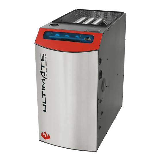
9700 SERIES
TWO STAGE HIGH EFFICIENCY
(CONDENSING) FORCED AIR GAS FURNACE
SAFETY INFORMATION
WARNING
!
ELECTRICAL SHOCK, FIRE OR
EXPLOSION HAZARD
Failure to follow safety warnings exactly
could result in serious injury, death or
property damage.
Improper servicing could result in
dangerous operation, serious injury, death
or property damage.
- Installation and service must be performed by a
qualifi ed installer, service agency or the gas supplier.
- Before servicing, disconnect all electrical power to
furnace.
- When servicing controls, label all wires prior to
disconnecting. Reconnect wires correctly.
- Verify proper operation after servicing.
- Do not store or use gasoline or other fl ammable
vapors and liquids in the vicinity of this or any other
appliance.
- WHAT TO DO IF YOU SMELL GAS:
• Do not try to light any appliance.
• Do not touch any electrical switch; do not use
any phone in your building.
• Leave the building immediately.
• Immediately call your gas supplier from a
neighbour's phone. Follow the gas supplier's
instructions.
• If you cannot reach your gas supplier, call the fi re
department.
Phone (705)721-1212 • Fax (705)722-6031 • www.napoleonheatingandcooling.com • ask@napoleonproducts.com
$10.00
OPERATING INSTRUCTIONS
CERTIFIED TO ANSI Z21.47b / CSA 2.3b-2008
!
Wolf Steel Ltd., 24 Napoleon Rd., Barrie, ON, L4M 0G8 Canada /
103 Miller Drive, Crittenden, Kentucky, USA, 41030
INSTALLATION AND
MANUFACTURER RESERVES THE RIGHT TO DISCONTINUE, OR CHANGE
AT ANY TIME, SPECIFICATIONS OR DESIGNS WITHOUT NOTICE AND
WITHOUT INCURRING OBLIGATIONS.
1
Patent Pending
Annual Fuel Utilization Efficiency (AFUE)
Gas- or Propane-fired forced-air furnace
with a high efficiency motor
97.0
90%
98%
W415-1064 / 11.11.11
Advertisement
Table of Contents
Troubleshooting

Related Manuals for Napoleon 9700 SERIES


Summary of Contents for Napoleon 9700 SERIES
-
Page 1: Safety Information
AT ANY TIME, SPECIFICATIONS OR DESIGNS WITHOUT NOTICE AND department. WITHOUT INCURRING OBLIGATIONS. Wolf Steel Ltd., 24 Napoleon Rd., Barrie, ON, L4M 0G8 Canada / 103 Miller Drive, Crittenden, Kentucky, USA, 41030 Phone (705)721-1212 • Fax (705)722-6031 • www.napoleonheatingandcooling.com • ask@napoleonproducts.com W415-1064 / 11.11.11... -
Page 2: Table Of Contents
TABLE OF CONTENTS INTRODUCTION SAFETY SYMBOLS AND WARNINGS SAFETY RULES CODES INSTALLATION REQUIREMENTS SPECIFIC TO THE STATE OF MASSACHUSETTS FOR DIRECT VENT, MECHANICAL VENT, AND DOMESTIC HOT WATER APPLIANCES. FURNACE SIZING LOCATION OF UNIT GENERAL GUIDELINES OTHER CONSIDERATIONS INSTALLATION IN UPFLOW POSITION AIR CONDITIONING COMBUSTIBLE CLEARANCES DUCTWORK... -
Page 3: Introduction
15.0 LOW VOLTAGE WIRING 15.1 SINGLE STAGE THERMOSTAT 15.2 TWO STAGE THERMOSTAT 15.3 THERMOSTAT LOCATION 16.0 OPTIONAL ACCESSORIES (FIELD SUPPLIED/INSTALLED) 16.1 ELECTRIC AIR CLEANER 16.2 POWER HUMIDIFIER 16.3 EMERGENCY HEAT MODE 17.0 STARTUP PROCEDURES 17.1 TO START THE FURNACE 17.2 TO SHUT DOWN THE FURNACE 17.3 SEQUENCE OF OPERATION... -
Page 4: Safety Symbols And Warnings
2.0 SAFETY SYMBOLS AND WARNINGS Understand and pay particular attention to the words DANGER, WARNING, and CAUTION and the following defi ned symbols are used throughout this manual to notify the reader of potential hazards of varying risk levels. DANGER INDICATES AN IMMINENTLY HAZARDOUS SITUATION WHICH, IF NOT AVOIDED, WILL RESULT IN DEATH OR SERIOUS INJURY. -
Page 5: Safety Rules
WARNING IMPROPER INSTALLATION, ADJUSTMENT, ALTERATION, SERVICE OR MAINTENANCE CAN CAUSE INJURY, PROPERTY DAMAGE OR LOSS OF LIFE. REFER TO THIS MANUAL. INSTALLATION AND SERVICE MUST BE PERFORMED BY A QUALIFIED INSTALLER, SERVICE AGENCY OR THE GAS SUPPLIER. THESE INSTRUCTIONS ARE INTENDED AS AN AID TO QUALIFIED SERVICE PERSONNEL FOR PROPER INSTALLATION, ADJUSTMENT AND OPERATION OF THIS FURNACE. - Page 6 2. Electrical connections must be made in accordance with: a. Any applicable local codes, by-laws and regulations. b. Canada: current edition of CAN/CSA C22.1, Canadian Electrical Code (Part 1). c. United States: current edition of ANSI/NFPA 70, National Electrical Code. Codes and additional information may be obtained from: Canadian Standards Association American Gas Association...
- Page 7 WARNING WHEN THIS FURNACE IS INSTALLED IN A RESIDENTIAL GARAGE, IT MUST BE INSTALLED SO THE BURNERS AND IGNITION SOURCE ARE LOCATED NO LESS THAN 18” ABOVE THE FLOOR TO PREVENT THE RISK OF IGNITING FLAMMABLE VAPORS WHICH MAY BE PRESENT IN THE GARAGE. THE FURNACE MUST BE LOCATED OR PROTECTED TO AVOID PHYSICAL DAMAGE BY VEHICLES.
-
Page 8: Installation Requirements Specific To The State Of Massachusetts For Direct Vent, Mechanical Vent, And Domestic Hot Water Appliances
INSTALLATION REQUIREMENTS SPECIFIC TO THE STATE OF MASSACHUSETTS FOR DIRECT VENT, MECHANICAL VENT, AND DOMESTIC HOT WATER APPLIANCES. For all side wall horizontally vented gas fueled equipment installed in every dwelling, building or structure used in whole or in part for residential purposes, including those owned or operated by the commonwealth and where the side wall exhaust vent termination is less than seven feet above fi... - Page 9 7. INSTALLATION INSTRUCTIONS: A copy of all installation instructions, and any instructions relating to venting shall remain with the furnace at the completion of the installation. FIGURE 2 - FURNACE COMPONENTS LEGEND 1. Combustion Air Intake Fitting 13. Two Speed Exhauster 2.
-
Page 10: Furnace Sizing
3.0 FURNACE SIZING The maximum hourly heat loss for each heated space shall be calculated in accordance with the procedures described in the manuals of the Heating, Refrigeration and Air Conditioning Institute of Canada (HRAI), or by any other method which is suitable for local conditions, provided the results obtained are in substantial agreement with, and not less than those obtained using the procedure described in their manuals. -
Page 11: Location Of Unit
4.0 LOCATION OF UNIT GENERAL GUIDELINES 1. Select a location where the exhaust and combustion air piping can be routed between the furnace and their terminations with a minimum of lengths and fi ttings. Be sure to check that the proposed termination location will meet code requirements with respect to location and minimum clearances. -
Page 12: Installation In Upflow Position
INSTALLATION IN UPFLOW POSITION UPFLOW INSTALLATION: Vent positioning, pressure switch location and drain locations shall be performed in accordance with instructions in the appropriate sections of this manual. NON-SUSPENDED INSTALLATION: Maintain clearances to combustibles as outlined in Figure 1, Table B. The furnace must be supported in such a way as to not allow twisting or sagging of the cabinet. -
Page 13: Combustible Clearances
5.0 COMBUSTIBLE CLEARANCES Figure 1, Table B provides the certifi ed clearances to combustibles and dimensional information. Also see the appliance rating plate affi xed to the furnace for specifi c model number, serial number and clearance to combustibles information. IMPORTANT THIS FURNACE REQUIRES A MINIMUM OF 24”... -
Page 14: Ductwork
6.0 DUCTWORK Proper airfl ow is required for the correct operation of this furnace. Insuffi cient airfl ow may cause erratic operation, could cause the furnace to cycle on the high temperature limit, and may damage the heat exchanger. Excessive airfl ow may result in an excessively noisy duct system and may result in undesirable consequences such as creating uncomfortable drafts. -
Page 15: Ductwork Steps
DUCTWORK STEPS 1. Position the furnace to minimize ductwork length and fi ttings. 2. Cut open a return air inlet. The choices are furnace bottom, either side, or any combination thereof (i.e., two sides or a side and the bottom).In all cases, cut the return air opening the full width of the return air markers on the side panel. -
Page 16: Venting And Combustion Piping
7.0 VENTING AND COMBUSTION PIPING WARNING READ, UNDERSTAND AND FOLLOW ALL INSTRUCTIONS IN THIS SECTION. FAILURE TO PROPERLY VENT OR SUPPLY COMBUSTION AIR TO THIS FURNACE CAN CAUSE CAR- BON MONOXIDE POISONING, OR AN EXPLOSION OR FIRE, RESULTING IN PROPERTY DAMAGE, PERSONAL INJURY OR LOSS OF LIFE. -
Page 17: Non-Direct Vent Furnace Installations Using Indoor Combustion Air (One Pipe System)
8.0 NON-DIRECT VENT FURNACE INSTALLATIONS USING INDOOR COMBUSTION AIR (ONE PIPE SYSTEM) The furnace, although designed as a direct vent type appliance, may be installed with the intake vent inside the structure. WARNING THIS FURNACE AND ANY OTHER FUEL BURNING APPLIANCE MUST BE PROVIDED WITH ENOUGH FRESH AIR FOR PROPER COMBUSTION AND VENTILATION OF THE FLUE GASES. -
Page 18: Determining Combustion Air
Combustion air must be free of acid forming chemicals such as sulphur, fl uorine and chlorine. These elements are found in aerosol sprays, detergents, bleaches, cleaning solvents, air fresheners, paint and varnish removers, refrigerants, and many other commercial and household products. When burned in a gas fl ame, vapors from these products form acid compounds. -
Page 19: Case 3: Furnace Located In A Confined Space, Outdoor Air From Attic Or Crawl Space
IMPORTANT: IF AN EXHAUST FAN, FIREPLACE, CLOTHES DRYER OR ANY SIMILAR DEVICE IS PRESENT IN THE INDOOR AREA FROM WHICH THE COMBUSTION AND VENTILATION AIR WILL BE DRAWN, NEGATIVE PRESSURE COULD BE A PROBLEM IF NATURAL INFILTRATION FROM THE OUTDOORS DOES NOT MATCH THE RATE AT WHICH AIR IS EXHAUSTED. -
Page 20: Case 4: Furnace Located In A Confined Space, Outdoor Air Ducted Horizontally
8.1.4 CASE 4: FURNACE LOCATED IN A CONFINED SPACE, OUTDOOR AIR DUCTED HORIZONTALLY Similar to Case 3, outdoor air for combustion and ventilation may be drawn through horizontal ducting. The free area for each opening is calculated on the basis of a minimum of 1 square inch per 2000 Btu/hr input. The following table shows minimum free areas and round pipe sizes when drawing combustion air horizontally from the outdoors for the furnace only. -
Page 21: Venting Guidelines
9.0 VENTING GUIDELINES CAUTION FAILURE TO FOLLOW ALL VENTING GUIDELINES MAY RESULT IN ERRATIC FURNACE OPERATION, FREEZE-UP OF THE EXHAUST AIR PIPING, OR SOOTING OF THE FURNACE. WARNING READ AND FOLLOW ALL INSTRUCTIONS IN THIS SECTION. FAILURE TO PROPERLY VENT THIS FURNACE CAN CAUSE CARBON MONOXIDE POISONING OR AN EXPLOSION OR FIRE RESULTING IN PROPERTY DAMAGE, PERSONAL INJURY OR LOSS OF LIFE. -
Page 22: Vent Termination
FIGURE 8 - STANDARD (STRAIGHT) HORIZONTAL VENT DETAIL RECOMMENDED *18” MIN. FOR COLD CLIMATES (SUSTAINED 0°F (-17°C) FOR 24 OR MORE CONSECUTIVE HOURS WARNING DO NOT CONNECT FURNACE TO A CHIMNEY OR FLUE SERVING OTHER APPLIANCES OR A SOLID FUEL BURNING APPLIANCE. VENT TERMINATION Horizontal vents should pass through TABLE 4 - DIRECT AND NON-DIRECT VENT LENGTHS... -
Page 23: In Canada
FIGURE 10 - VERTICAL VENTING FIGURE 9 - PERISCOPED VENT DETAIL RECOMMENDED *18” MIN. FOR COLD CLIMATES (SUSTAINED 0°F (-17°C) FOR 24 OR MORE CONSECUTIVE HOURS CAUTION MOISTURE IN THE FLUE GASES CONDENSES AS IT LEAVES THE TERMINAL. THIS MOISTURE CAN FREEZE ON EXTERIOR WALLS, ON SOFFITS, AND OTHER NEARBY OBJECTS. -
Page 24: Furnace Venting Installations
• Locate the vent terminal 3 feet above any forced air inlet located within 10 feet. Any fresh air or make-up air inlet, such as for a dryer or furnace area is considered a forced air inlet. The vent terminal should be located no fewer than 6 feet from an inside corner formed by two exterior walls; a 10 foot distance is recommended. -
Page 25: Terminations
10.0 TERMINATIONS 10.1 COMBUSTION AIR HORIZONTAL - The combustion air termination is made up of a FIGURE 11 - STANDARD VERTICAL medium or long sweep 90° elbow pointing downward to prevent VENTING DETAIL rain from readily entering the combustion air intake piping. An intake screening is optional;... -
Page 26: Location
10.5 LOCATION Avoid locating the terminals where the fl ue gas could become stagnant and allow recirculation into the combustion air intake. Avoid locating the terminal in locations where dripping condensate may cause problems such as sidewalks, patios, above planters, near windows where exhaust gases may cause fogging, etc. Avoid locating the termination too close to shrubs and other vegetation. -
Page 27: In Canada
If more than two furnaces are being installed in close proximity, each additional combustion air intake and exhaust termination set shall not terminate less than 12 in (300 mm) apart. Note: Canadian installations of 120000 Btu/hr require 3 ft (900 mm). WARNING RECIRCULATION OF FLUE GASES MAY OCCUR CAUSING THE INTAKE PIPE TO FREEZE SHUT DURING COLD WEATHER OPERATION IF THE VENTING SYSTEM IS NOT... - Page 28 FIGURE 14A - DIRECT VENT TERMINAL CLEARANCES W415-1064 / 11.11.11...
- Page 29 FIGURE 14B - NON-DIRECT VENT TERMINAL CLEARANCES W415-1064 / 11.11.11...
-
Page 30: Routing Options
10.9.1 ROUTING OPTIONS This furnace must be installed in the upfl ow position only. Figure 22 on the following page shows the three vent installation positions. The installer must consider the following services: gas pipe, electrical power, drain trap, intake and exhaust vents. Also consider the air conditioning connections and drain, access to fi... -
Page 31: Preparations For Vent And Draining Option
Affi x the condensate trap assembly to the interior of the side panel in the blower compartment. Three plastic drain hose clamps are provided in the parts bag. The large one (black) is used for securing the drain hose to the front manifold cover drain outlet. The medium one (white) is used for securing the drain hose to the 5/8”... - Page 32 FIGURE 22 - UPFLOW VENT AND DRAINING OPTION LEFT VENT INSTALLATION TOP VENT INSTALLATION GASKET “A” ONLY RIGHT VENT INSTALLATION IMPORTANT: • PRIME CONDENSATE TRAP WITH WATER AND CUT DRAIN HOSES TO PROPER LENGTH. • CUT PRESSURE SWITCH TUBING TO PROPER LENGTH. NOTE Upfl...
-
Page 33: Condensate Drains
11.0 CONDENSATE DRAINS The furnace may condense as much as a 4½ pounds of water per hour (approximately 2 imperial quarts, 2½ U.S. quarts or 2¼ liters). It is necessary to make provisions for draining the condensate away. The furnace is supplied with a drain trap assembly. -
Page 34: Alternate Condensate Drain Piping Installation Using Pvc Or Cpvc
IMPORTANT: THE CONDENSATE DRAIN TRAP ASSEMBLY SHOULD BE FULL OF WATER (PRIMED) BEFORE STARTING THE FURNACE. TO FILL THE CONDENSATE DRAIN TRAP ASSEMBLY, TEMPORARILY REMOVE THE VENT DRAIN HOSE FROM THE EXHAUSTER ASSEMBLY ELBOW/DRAIN FITTING, AND POUR APPROXIMATELY ONE CUP OF WATER DOWN THE HOSE. -
Page 35: Condensate Neutralizers
FIGURE 19 FIGURE 20 A ½” PVC coupling or bushing will fi t snug over the ½” rubber hose. A ¾” CPVC coupling or bushing will fi t snug over the 5/8” rubber hose. This method ensures a water tight seal and also allows the condensate trap to be easily removed for service. -
Page 36: Gas Supply And Piping
12.0 GAS SUPPLY AND PIPING 12.1 GAS SUPPLY WARNING THIS FURNACE IS FACTORY EQUIPPED TO BURN NATURAL GAS ONLY. IMPORTANT: • CONNECT THIS FURNACE ONLY TO GAS SUPPLIED BY A COMMERCIAL UTILITY OR SUPPLIER. PRIVATE GAS WELLS DO NOT GENERALLY PROVIDE GAS WITH CONSISTENT, UNIFORM AND PREDICTABLE HEATING VALUES AND DENSITIES. -
Page 37: Gas Inlet Pressure
IMPORTANT: ALWAYS USE A BACKUP WRENCH TO PREVENT TWISTING OF THE GAS VALVE. ANY STRAINS ON THE GAS VALVE CAN AFFECT POSITIONING OF THE ORIFICES RELATIVE TO THE BURNERS. THIS COULD RESULT IN FAULTY BURNER OPERATION. Install a manual gas shut-off valve and dirt pocket as close to the furnace as possible. Some local codes call for the manual gas shut-off valve to be located between 4 to 5 feet above fl... -
Page 38: Conversions
13.0 CONVERSIONS HIGH ALTITUDE: In Canada, the modifi cations for high altitude are based on a 10% reduction of input capacity for elevations from 2000 - 4500 feet. In the United States, the modifi cations for high altitude are based on a 4% reduction of input capacity for every 1000 feet above 2000 feet above sea level. -
Page 39: Setting The Manifold Gas Pressure
9. If working on a natural gas system, contact the gas utility. They may insist on any service regulator adjustments being made by their own staff If problems were encountered with obtaining enough pressure on the manifold, fi rst examine the gas piping system to ensure that it is correctly sized. -
Page 40: Checking Furnace Input
WARNING ALL REGULATOR ADJUSTMENTS MUST BE DONE BY A TRAINED, QUALIFIED TECHNICIAN. IMPROPER MODIFICATIONS OR ADJUSTMENTS CAN RESULT IN FIRE OR EXPLOSION CAUSING PROPERTY DAMAGE, SEVERE PERSONAL INJURY OR LOSS OF LIFE. 7. Remove the manometer hose from the outlet pressure tap boss, and tighten the outlet pressure tap screw using the 3/32”... -
Page 41: Electrical Specifications
14.0 ELECTRICAL SPECIFICATIONS 14.1 ELECTRICAL WIRING AND CONNECTIONS Before proceeding with the electrical connections, ensure that the available electrical supply is compatible with the voltage, frequency and phase listed on the appliance rating plate. All furnaces are rated 120 vac, 60 Hz, 1 Ø. The amperage rating is 15 amps or less. Each furnace requires a dedicated 15 amp over-current device, either a 15 amp circuit breaker or a 15 amp Type D time delay fuse. -
Page 42: Furnace Connection
FIGURE 36 - INTEGRATED FURNACE IGNITION CONTROL 5A FUSE 24 VAC MOLEX PARK TERMINALS INTERFACE ELECTRONIC AIR CLEANER POWER THERMOSTAT HUMIDIFIER TERMINALS 120 VAC MOLEX FAULT CODE BUTTON 120 VAC NEUTRAL RED STATUS HEAT STAGING CONNECTIONS JUMPER P5 14.2 FURNACE CONNECTION The furnace is shipped fully wired except for the connections to the house wiring. -
Page 43: Low Voltage Wiring
15.0 LOW VOLTAGE WIRING The thermostat and control wiring should be a minimum of 18 AWG copper. Excessive lengths of wire may result in enough voltage drop to impair the proper functioning of the furnace. For thermostat wires in excess of 25 feet, use 16 AWG;... -
Page 44: Optional Accessories (Field Supplied/Installed)
16.0 OPTIONAL ACCESSORIES (FIELD SUPPLIED/ INSTALLED) 16.1 ELECTRIC AIR CLEANER The integrated furnace control has provisions to supply power and control an electronic air cleaner rated at 120vac, 1.0 amp max. 120 volt power will be available at this terminal whenever the circulating fan is operating in the heating or cooling modes. -
Page 45: Startup Procedures
17.0 STARTUP PROCEDURES This furnace is equipped with a HSI (Hot Surface Ignition) device. Each time that the room thermostat calls for heat, the HSI lights the main burners directly. See the lighting instructions on the furnace. NOTE It is recommended that the drain trap assembly be primed before the initial startup. Refer to the instructions on how to prime the condensate trap on the previous pages in this manual. -
Page 46: Sequence Of Operation
17.4 PROGRAMMABLE THERMOSTAT (OPTION) The 9700 Series furnace has an optional programmable two stage Napoleon® Elite Thermostat. For instruction on how to operate and program this unit, please refer to the manual and installation instructions provided with the Napoleon® Elite Thermostat Kit. -
Page 47: Air Flow
18.0 AIR FLOW For proper furnace operation, air fl ow over the heat exchanger is of utmost importance. Insuffi cient airfl ow accelerates metal fatigue and possible failure in the heat exchanger, and decreases effi ciency. Excessive airfl ow promotes accelerated corrosion of the heat exchanger. TABLE 1 - RANGE OF TEMPERATURE RISE IMPORTANT: Furnace Models... -
Page 48: Calculating Air Flow
18.2 CALCULATING AIR FLOW There are circumstances where it may be desirable to know the air fl ow delivery through the duct system, such as when estimating the amount of air fl ow available for Output air conditioning. This can be done by direct measurement with CFM = ∆T 1.085 x... -
Page 49: Dehumidification - Ecm
CFM by 15% 18.7 UV LAMP REPLACEMENT The 9700 Series furnace comes equipped with an ultraviolet lamp located on the right side of the heat exchanger. This unit helps to reduce the number of bacteria within the household and also helps to clear the “A”... - Page 50 3. Using 1/4” socket driver, remove the single mounting screw that retains the lamp bracket to the blower division. The bulb unit can now be removed from the furnace. Be careful not to break the existing bulb when removing it through the blower division. FIGURE 23 FIGURE 24 FIGURE 25...
-
Page 51: Maintenance And Troubleshooting
19.0 MAINTENANCE AND TROUBLESHOOTING WARNING DISCONNECT THE ELECTRICAL POWER SUPPLY TO THE FURNACE BEFORE ATTEMPTING ANY MAINTENANCE. FAILURE TO DO SO CAN CAUSE ELECTRICAL SHOCK RESULTING IN PERSONAL INJURY OR LOSS OF LIFE. CAUTION LABEL ALL WIRES PRIOR TO DISCONNECTION WHEN SERVICING CONTROLS. WIRING ERRORS CAN CAUSE IMPROPER AND DANGEROUS OPERATION. -
Page 52: Lubrication
19.2 LUBRICATION Both the exhauster motor and circulating fan motor are ball bearing type motors. Neither requires routine lubrication. IMPORTANT: THE MOTOR BEARINGS WERE PRE-LUBRICATED BY THE MOTOR MANUFACTURER. DO NOT ATTEMPT TO LUBRICATE THEM. EXCESS LUBRICATION WILL VOID THE WARRANTY, SHORTEN THE SERVICE LIFE OF THE MOTORS, AND WILL ATTRACT THE BUILDUP OF DUST AND DIRT. -
Page 53: Annual Inspection/Service
19.6 ANNUAL INSPECTION/SERVICE It is recommended that the furnace be inspected annually by a qualifi ed installation contractor, service agency or fuel supplier. Your annual inspection will normally cover the following: HEAT EXCHANGER - The heat exchanger should be inspected for corrosion. The fl ue passages (heat exchanger tubes) should be free of scale or excessive corrosion. -
Page 54: Troubleshooting Flowchart
19.7 TROUBLESHOOTING FLOWCHART SEQUENCE OF OPERATION W415-1064 / 11.11.11... -
Page 55: Diagnostic Codes For Status Led
19.10 INTERNAL LIGHTING SYSTEM The 9700 Series is equipped with internal LED service lights. One is located in the upper vestibule area and the other is located in the lower blower compartment. These lights are only activated when the bottom door is removed and the door switch is deactivated. The purpose of the interior lighting is to ease servicing the unit. -
Page 56: Wire Diagram For Two Stage Furnace With Ecm
20.0 WIRE DIAGRAM FOR TWO STAGE FURNACE WITH ECM 2.3 24 VAC 120 VAC P13-5 P15-9 120 VAC NEUTRAL NEUT3 FUSE P21-5 P22-4 COOL1 NEUT4 FAN1 NEUT5 NEUT1 2ND STAGE HEAT1 ELECTRONIC CLEANER 1ST STAGE HEAT1 EAC1 P13-11 CONT1 HIGH LIMIT1 HUMIDIFIER1 HUM1 ROLLOUT1... -
Page 57: Warranty
WARRANTY Napoleon® products are designed with superior components and materials, assembled by trained craftsmen who take great pride in their work. The complete appliance is again thoroughly inspected by a qualifi ed technician before packaging to ensure that you, the customer, receives the quality product that you expect from Napoleon®. -
Page 58: Replacement Parts List
22.0 REPLACEMENT PARTS LIST Contact your dealer or the factory for questions concerning prices and policies on replacement parts. Normally all parts can be ordered through your Authorized dealer / distributor. FOR WARRANTY REPLACEMENT PARTS, A PHOTOCOPY OF THE ORIGINAL INVOICE WILL BE REQUIRED TO HONOUR THE CLAIM. -
Page 59: Service History
23.0 SERVICE HISTORY W415-1064 / 11.11.11... -
Page 60: Notes
24.0 NOTES W415-1064 / 11.11.11...