Table of Contents
Advertisement
Date of Purchase:
Serial Number:
Code Number:
Model:
Where Purchased:
Safety Depends on You
Lincoln arc welding and cutting equipment is designed and
built with safety in mind. However, your overall safety can be
increased by proper installation ... and thoughtful operation
on your part. DO NOT INSTALL, OPERATE OR REPAIR
THIS EQUIPMENT WITHOUT READING THIS MANUAL
AND
THE
SAFETY
PRECAUTIONS
THROUGHOUT. And, most importantly, think before you act
and be careful.
TABLE OF CONTENTS
Safety . . . . . . . . . . . . . . . . . . . . . . . . . . . . . . . . .2
Introduction . . . . . . . . . . . . . . . . . . . . . . . . . . . . .8
Technical Specification . . . . . . . . . . . . . . . . . . . . .9
Installation . . . . . . . . . . . . . . . . . . . . . . . . . . . . . .10
Operation . . . . . . . . . . . . . . . . . . . . . . . . . . . . . . .17
Learn to Weld . . . . . . . . . . . . . . . . . . . . . . . . . . .29
Accessories . . . . . . . . . . . . . . . . . . . . . . . . . . . . .46
Maintenance . . . . . . . . . . . . . . . . . . . . . . . . . . . .49
Troubleshooting . . . . . . . . . . . . . . . . . . . . . . . . . .54
Wiring Diagram . . . . . . . . . . . . . . . . . . . . . . . . . .56
Parts . . . . . . . . . . . . . . . . . . . . . . . . . . . . . . . . . .57
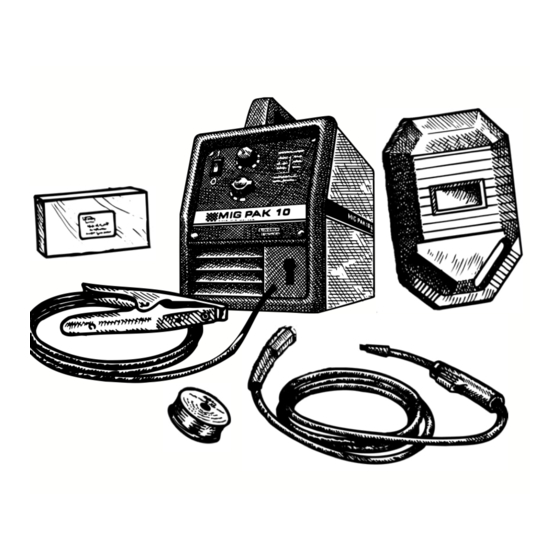
M M I I G G - - P P A A K K 1 1 0 0
La Seguridad Depende de Usted
Los equipos de corte y soldadura al arco Lincoln han sido
diseñados y construidos teniendo en cuenta su seguridad.
No obstante, ésta se verá incrementada si la instalación se
realiza correctamente, y si pone atención en el manejo de
los mismos.
NO INSTALE, UTILICE O REPARE ESTE
CONTAINED
EQUIPO SIN ANTES HABER LEIDO ESTE MANUAL Y LAS
MEDIDAS DE SEGURIDAD QUE CONTIENE. Y, lo más
importante, piense antes de actuar, y tenga mucho cuidado.
TABLA DE CONTENIDO
Seguridad . . . . . . . . . . . . . . . . . . . . . . . . . . . . . . . .2
Introducción . . . . . . . . . . . . . . . . . . . . . . . . . . . . . . .8
Especificaciones Técnicas . . . . . . . . . . . . . . . . . . . .9
Instalación . . . . . . . . . . . . . . . . . . . . . . . . . . . . . . . .10
Operación . . . . . . . . . . . . . . . . . . . . . . . . . . . . . . . .17
Aprendiendo A Soldar . . . . . . . . . . . . . . . . . . . . . . .29
Accesorios . . . . . . . . . . . . . . . . . . . . . . . . . . . . . . . .46
Mantenimiento . . . . . . . . . . . . . . . . . . . . . . . . . . . . .49
Localización de averías . . . . . . . . . . . . . . . . . . . . . .54
Diagramas De Cableado . . . . . . . . . . . . . . . . . . . . . .56
Partes . . . . . . . . . . . . . . . . . . . . . . . . . . . . . . . . . . .57
22801 St. Clair Ave. Cleveland, Ohio 44117-1199 U.S.A.
WEB SITE: www.lincolnelectric.com
Tel. 216.481.8100
OPERATOR'S MANUAL
MANUAL DE OPERACIÓN
MANUEL DE L'OPÉRATEUR
La sécurité dépend de vous
Le matériel de soudage et de coupage à l'arc Lincoln est
conçu et construit en tenant compte de la sécurité. Toutefois,
la sécurité en général peut être accrue grâce à une bonne
installation... et à la plus grande prudence de votre part. NE
PAS INSTALLER, UTILISER OU RÉPARER CE MATÉRIEL
SANS AVOIR LU CE MANUEL ET LES MESURES DE
SÉCURITÉ QU'IL CONTIENT.
réfléchissez avant d'agir et exercez la plus grande prudence.
TABLE DES MATIÈRES
Sécurité....................................................................2
Introduction ..............................................................8
Fiche technique .......................................................9
Installation ...............................................................10
Fonctionnement .......................................................17
Apprentissage du soudage ......................................29
Accessoires..............................................................46
Entretien...................................................................49
Dépannage ..............................................................54
Schéma de câblage .................................................56
Pièces ......................................................................57
Copyright © 2001 Lincoln Global Inc.
IM551-C
May, 2002
RETURN TO MAIN INDEX
Et, par dessus tout,
Advertisement
Table of Contents
Troubleshooting

Related Manuals for Lincoln Electric MIG-PAK 10


Summary of Contents for Lincoln Electric MIG-PAK 10
- Page 1 Date of Purchase: Serial Number: Code Number: Model: Where Purchased: Safety Depends on You Lincoln arc welding and cutting equipment is designed and built with safety in mind. However, your overall safety can be increased by proper installation ... and thoughtful operation on your part.
-
Page 2: Safety
ANSI Standard Z49.1” from the American Welding Society, P.O. Box 351040, Miami, Florida 33135 or CSA Standard W117.2-1974. A Free copy of “Arc Welding Safety” booklet E205 is available from the Lincoln Electric Company, 22801 St. Clair Avenue, Cleveland, Ohio 44117-1199. BE SURE THAT ALL INSTALLATION, OPERA-... - Page 3 SAFETY ELECTRIC AND MAGNETIC FIELDS may be dangerous 3.a. Electric current flowing through any conductor causes localized Electric and Magnetic Fields (EMF). Welding current creates EMF fields around welding cables and weldingmachines 3.b. EMF fields may interfere with some pacemakers, and welders having a pacemaker should consult their physician before welding.
- Page 4 SAFETY WELDING SPARKS can cause fire or explosion. 4.a. Remove fire hazards from the welding area. If this is not possible, cover them to prevent the welding sparks from starting a fire. Remember that welding sparks and hot materials from welding can easily go through small cracks and openings to adjacent areas.
- Page 5 SAFETY ELECTRIC SHOCK can kill. 5.a. The electrode and work (or ground) circuits are electrically “hot” when the welder is on. Do not touch these “hot” parts with your bare skin or wet cloth- ing. Wear dry, hole-free gloves to insulate hands.
- Page 6 SAFETY FUMES AND GASES can be dangerous. 6.a.Welding may produce fumes and gases hazardous to health. Avoid breathing these fumes and gases.When welding, keep your head out of the fume. Use enough ventila- tion and/or exhaust at the arc to keep fumes and gases away from the breathing zone.
- Page 7 SAFETY CYLINDER may explode if damaged. 7.a. Use only compressed gas cylinders containing the correct shielding gas for the process used and properly operat- ing regulators designed for the gas and pressure used. All hoses, fittings, etc. should be suitable for the application and maintained in good condition.
-
Page 8: Introduction
INTRODUCTION Read the entire manual before installing and operating the MIG-PAK WARNING ELECTRIC SHOCK can kill. • Only qualified personnel should installation or operate this equipment. • Machine must be plugged into a receptacle which is grounded per any national, local or other applicable electrical codes. -
Page 9: Technical Specification
TECHNICAL SPECIFICATIONS INPUT – SINGLE PHASE ONLY Voltage/Frequency Input Current 115V/60Hz 20 Amps - Rated Output 115V/60Hz 15 Amps - CSA Rated output RATED OUTPUT Duty Cycle Amps Volts CSA RATED OUTPUT Duty Cycle Amps Volts OUTPUT RANGE Welding Current Range Rated DC Output: 30 - 88 amps Rated CSA DC Output:... -
Page 10: Installation
INSTALLATION IDENTIFY AND LOCATE COMPONENTS If you have not already done so, unpack the MIG-PAK from its carton and remove all packing material around the MIG- PAK. Remove the following loose items from the carton): Ensamble de la antorcha y cable MIG-PAK Work clamp Pinza de trabajo... - Page 11 6. Wire Feed Gearbox. 7. Cable Hanger. 8. Thumbscrew. 9. Circuit Breaker 10. Blank Panel Assembly MIG-PAK 10 Figure 1 INSTALACIÓN SELECCION DEL LUGAR ADECUADO Coloque la soldadora en un lugar seco y donde circule aire limpio por las ventilas de la parte posterior y fuera de la unidad.
- Page 12 INSTALLATION WORK CLAMP INSTALLATION Attach the work clamp per the following: Unplug the machine or turn the power switch to the OFF position. Insert the work cable terminal lug with the larger hole through the strain relief hole in the work clamp as shown in Figure 2.
- Page 13 INSTALLATION FIGURE 3 GUN INSTALLATION As shipped from the factory, the MIG PAK 10 is ready to feed .023" – .025" (0.6 mm) solid wire. If .030" (0.8 mm) solid wire is to be used, change the contact tip to the appropriate size. Connecting Gun Cable to the MIG PAK 1.
- Page 14 INSTALLATION 4. Connect the gun trigger control lead terminals to the two insulated 1/4" (6.4 mm) tab terminal connector bushings located below the “Gun Trigger Connection” decal in the wire feed section (4). Either lead can go to either con- nector.
- Page 15 INSTALLATION WARNING BUILDUP OF SHIELDING GAS may harm health or kill. • Shut off shielding gas supply when not in use. • SEE AMERICAN NATIONAL STANDARD Z- 49.1, “SAFETY IN WELDING AND CUT- TING” PUBLISHED BY THE AMERICAN WELDING SOCIETY. ------------------------------------------------------------------------------- 1.
- Page 16 INSTALLATION INPUT CONNECTIONS Refer to Figure 5. The MIG PAK has a power input cable located on the rear of the machine. Figure 5 GAS SOLENOID INLET FITTING POWER INPUT CABLE CODE REQUIREMENTS INPUT CONNECTIONS WARNING • This welding machine must be connected to power source in accordance with applicable electrical codes.
-
Page 17: Operation
OPERATION Read the entire manual before installing and operating the MIG PAK 10. SAFETY PRECAUTIONS WARNING ELECTRIC SHOCK can kill. • Do not touch electrically live parts or elec- trode with skin or wet clothing. Insulate yourself from work and ground. •... - Page 18 OPERATION The MIG PAK 10 is ideally suited for individuals having access to 115 volt AC input power, and wanting the ease of use, quality and dependability of both gas metal arc welding or GMAW (also known as MIG welding) and the Innershield electrode process (self shielded flux cored or FCAW).
- Page 19 OPERATION WELDING CAPABILITY The MIG PAK 10 is rated at 88 amps, 18 volts, at 20% duty cycle on a ten minute basis. CSA rated output at 62 amps at 20 volts at 20% duty cycle. It is capable of higher output cur- rents at lower duty cycles.
- Page 20 OPERATION OPERACIÓN FONCTIONNEMENT FIGURE 6a FIGURE 6b...
- Page 21 OPERATION WELDING SEQUENCE OF OPERATION WIRE LOADING Refer to Figures 7 and 8. The machine power switch should be turned to the OFF (“O”) position before working inside the wire feed enclosure. The welder is shipped from the factory ready to feed 8" (200 mm) diameter spools with 2.2"...
- Page 22 OPERATION FIGURE 8 Optional Wire Spool Spindle 8” Wire Spool Be sure that this stud engages the hole in the wire spool. To Wire Drive Wire Spool must be pushed all the way on the spindle so that the spindle’s tab will hold it in place. The Wire Spool will rotate clockwise when wire is dereeled.
- Page 23 OPERATION The Wire Drive Feed Roll can accommodate two wire sizes by flipping the wire drive feed roll over. Figure 9 5. Close the idle roll arm (2) and latch the spring loaded pres- sure arm (1) in place. Rotate the spool counterclockwise if required in order to take up extra slack in the wire.
- Page 24 OPERATION 7. Remove gas nozzle and contact tip from end of gun. Gun Handle Gas Diffuser/ Contact Tip Figure 10 Gas Nozzle 8. Turn the MIG-PAK ON (“I”). 9. Straighten the gun cable assembly. 10. Depress the gun trigger switch and feed welding wire through the gun and cable.
- Page 25 OPERATION MAKING A WELD 1. See "Process Guidelines" in this section for selection of welding wire and shielding gas and for range of metal thicknesses that can be welded.. 2. See Aplication chart on the inside of the wire feed com- partment door for information on setting the MIG PAK 10 controls.
- Page 26 OPERATION Position gun over joint. End of wire may be lightly touch- ing the work. Lower welding helmet, close gun trigger, and begin welding. Hold the gun so the contact tip to work distance is about 3/8 inch (10 mm). To stop welding, release the gun trigger and then pull the gun away from the work after the arc goes out.
- Page 27 OPERATION TABLE 1 Voltage-Wire Speed Shielding Process Wire 16 ga 14 ga 12 ga 10 ga MIG DC+ .035 Dia 100% Argon 4043 Al Wire MIG DC+ .035 Dia 100% Argon D-10 5356 Al Wire MIG DC+ .030 Dia 98% Argon/ D-7.5 D-7.5 308L 2% Oxygen...
-
Page 28: Overload Protection
OPERATION WELDING WITH FCAW (Innershield) When using the FCAW process, the correct drive roll and electrode polarity must be used. See Work Cable Installation in INSTALLATION section for changing the polarity. Innershield welding kit K549-1 (for .035" / 0.9mm) is also available. -
Page 29: Learn To Weld
LEARNING TO WELD LEARNING TO WELD No one can learn to weld simply by reading about it. Skill comes only with practice. The following pages will help the inexperienced operator to understand welding and develop this skill. For more detailed information, order a copy of “New Lessons in Arc Welding”... - Page 30 LEARNING TO WELD WARNING Fumes and slag generated from Innershield type electrodes recom- mended for use with this welding machine can be toxic. • Avoid contact with eyes and skin. • Do not take internally. • Keep out of reach of children. •...
- Page 31 LEARNING TO WELD The “arc stream” is seen in the middle of the picture. This is the electric arc created by the electric current flowing through the space between the end of the wire electrode and the base metal. The temperature of this arc is about 6000°F, which is more than enough to melt metal.
- Page 32 LEARNING TO WELD When comparing the GMAW and FCAW processes, you can see that the principal difference between the two lies in the type of shielding used. GMAW uses gas for shielding, thus we have Gas Metal Arc Welding. FCAW uses the melting or burning of the core ingredients for shielding, and is thus termed Self-Shielded Flux Cored Arc Welding.
- Page 33 LEARNING TO WELD For FCAW (Innershield) Process 1. Do I want simplicity and portability? 2. Will welding be performed outdoors or under windy con- ditions? 3. Do I require good all position welding capability? 4. Will most welding be performed on 16 gauge and heav- ier, somewhat rusty or dirty materials? 5.
- Page 34 LEARNING TO WELD Butt Welds Place two plates side by side, leaving a space approximate- ly one half the thickness of the metal between them in order to get deeper penetration. Securely clamp or tack weld the plates at both ends, other- wise the heat will cause the plates to move apart.
- Page 35 LEARNING TO WELD Fillet Welds When welding fillet welds, it is very important to hold the wire electrode at a 45° angle between the two sides or the metal will not distribute itself evenly. The gun nozzle is generally formed at an angle to facilitate this. See Figure 20. 45°...
- Page 36 LEARNING TO WELD PROPER GUN ANGLE PROPER GUN ANGLE FOR GMAW PROCESS FOR FCAW PROCESS WELDING IN THE VERTICAL UP POSITION WELDING IN THE VERTICAL UP POSITION FIGURE 21 Vertical-down Welding Refer to Figure 22 Vertical-down welds are applied at a fast pace.
- Page 37 LEARNING TO WELD WELDING TECHNIQUES FOR THE SELF-SHIELDED FCAW PROCESS Four simple manipulations are of prime importance when welding. With complete mastery of the four, welding will be easy. They are as follows: 1. The Correct Welding Position Figure 23 illustrates the correct welding position for right handed people.
- Page 38 LEARNING TO WELD 3. The Correct Electrical Stickout (ESO) The electrical stickout (ESO) is the distance from the end of the contact tip to the end of the wire. (See Figure 24.) Once the arc has been established, maintaining the cor- rect ESO becomes extremely important.
- Page 39 LEARNING TO WELD Helpful Hints 1. For general welding, it is not necessary to weave the arc. Weld along at a steady pace. You will find it easier. 2. When welding on thin plate, you will find that you will have to increase the welding speed, whereas when weld- ing on heavy plate, it is necessary to go more slowly in order to get good penetration.
- Page 40 LEARNING TO WELD Contact Tip Punta de contacto Tube contact 4. After you strike the arc, practice the correct electrical stickout. Learn to distinguish it by its sound. 5. When you are sure that you can hold the correct electri- cal stickout, with a smooth “crackling”...
- Page 41 LEARNING TO WELD When using the GMAW process on light gauge material, weld from right to left (if you are right handed). This results in a colder weld and has less tendency for burn through. 2. The Correct Way To Strike An Arc Be sure the work clamp makes good electrical con- tact to the work.
- Page 42 LEARNING TO WELD 4. The Correct Welding Speed The important thing to watch while welding is the puddle of molten metal right behind the arc. See Figure 30. Do not watch the arc itself. It is the appearance of the pud- dle and the ridge where the molten Puddle solidifies that indicates correct welding speed.
- Page 43 LEARNING TO WELD Practice The best way of getting practice is to perform the following exercise. For the MIG-PAK, use the following: Mild Steel 16 gauge or 1/16 inch (1.6 mm) Electrode Lincolnweld 0.025 L-56 electrode CO 2 Voltage Setting “V” Wire Feed Speed “o|o”...
- Page 44 LEARNING TO WELD TROUBLESHOOTING WELDS Good welds have excellent appearance. To Eliminate Porosity (in order of importance): 1. Turn on gas supply, if used 2. Decrease voltage. 3. Increase stickout. 4. Increase WFS (wire feed speed). 5. Decrease drag angle. 6.
- Page 45 LEARNING TO WELD To Reduce Spatter (in order of importance): 1. Increase voltage. 2. Increase drag angle. 3. Decrease stickout. 4. Increase WFS (wire feed speed). 5. Decrease travel speed. 6. Check for correct gas, if used. To Correct Poor Penetration (in order of importance): 1.
-
Page 46: Accessories
ACCESSORIES OPTIONAL ACCESSORIES 1. K549-1 .035" (0.9 mm) Innershield® Welding Kit — Includes a contact tip, a gasless nozzle and a .035/.045" (.9/1.2 mm) cable liner. The fitting on the end of the liner is stenciled with the maximum rated wire size (.045"/1.2 mm). - Page 47 ACCESSORIES 6. K697-1 Power Cord Extension — Extension 115V power cord (20’/6.1m) allows extra convenience when work is located some distance away from power receptacle. INNERSHIELD (FCAW) CONVERSION Several changes are needed to convert the unit for operation with the Innershield (FCAW) process. The K549-1 or K549-2 Innershield Kits include all the necessary accessories for this conversion and are provided for this purpose.
- Page 48 ACCESSORIES REPLACEMENT PARTS Complete Gun and Cable Assembly L8311-6 (K530-5) Contact Tip .025” (0.6 mm) S19726-1 Contact Tip .030” (0.8 mm) S19726-2 Contact Tip .035” (0.9 mm) S19726-3 Contact Tip-Tapered .025” (0.6 mm) S20278-1 Contact Tip-Tapered .030” (0.8 mm) S20278-2 Contact Tip-Tapered .035”...
-
Page 49: Maintenance
MAINTENANCE SAFETY PRECAUTIONS WARNING ELECTRIC SHOCK can kill. • Disconnect input power by remov- ing plug from receptacle before working inside MIG-PAK. Use only grounded receptacle. Do not touch electrically “hot” parts inside MIG- PAK. • Have qualified personnel do the maintenance and trouble shooting work. - Page 50 MAINTENANCE GUN AND CABLE MAINTENANCE FOR MAGNUM 100L GUN Gun Cable Cleaning Clean cable liner after using approximately 300 lbs (136 kg) of solid wire or 50 lbs (23 kg) of flux-cored wire. Remove the cable from the wire feeder and lay it out straight on the floor. Remove the contact tip from the gun.
- Page 51 Replace the gun handle, trigger and dif- fuser. Replace the gas nozzle or gasless nozzle. CONFIGURATION OF COMPONENTS IN WIRE FEEDING SYSTEM Components shipped with MIG-PAK 10• Componentes enviados con la MIG PAK 10 Innershield Conversion Kit K549-1 .035” (0.9 mm) Juego de Conversión Innershield Aluminum or Stainless Kit* K664-2 .035 (0.9mm)
- Page 52 MAINTENANCE CHANGING DRIVE ROLL The drive roll has two grooves; one for .023" – .025" (0.6 mm) solid steel electrode and a larger knurled groove for .030" (0.8 mm) solid and .035" (0.9 mm) flux-cored steel electrode. As shipped, the drive roll is installed in the .030"/.035"...
- Page 53 MAINTENANCE CHANGING LINER NOTICE: The variation in cable lengths prevents the inter- changeability of liners. Once a liner has been cut for a par- ticular gun, it should not be installed in another gun unless it can meet the liner cutoff length requirement. Refer to Figure below.
-
Page 54: Troubleshooting
TROUBLESHOOTING No wire feed, weld output or gas flow when gun trig- ger is pulled. Fan does NOT operate. Make sure correct voltage is applied to the machine. Make certain that power switch is in the ON position. Make sure circuit breaker inside wire drive com- partment is reset. - Page 55 TROUBLESHOOTING Low or no gas flow when gun trigger is pulled. Wire feed, weld output and fan operate normally. Verify that gas solenoid is properly installed. Check gas supply, flow regulator and gas hoses. Check gun connection to machine for obstruc- tion or leaky seals.
-
Page 56: Wiring Diagram
MIG PAK 10 WIRING DIAGRAM MIG PAK 10 WIRING DIAGRAM NOTE: This diagram is for reference only. It may not be accurate for all machines covered by this manual. The specific diagram for a particular code is pasted inside the machine on one of the enclosure panels. HIGH VOLTAGE HIGH VOLTAGE can kill... -
Page 57: Parts
PARTS Order parts from an authorized Lincoln Service Facility. The following replacement parts listing is for reference only. Refer to parts page listing P272 for latest list. Part Description Descripción de las partes Voltage Control Switch Assembly Ensamble del Interruptor de Control de Voltaje Knob (Voltage Switch) Perilla (Interruptor de Voltaje) Line Switch... - Page 58 NOTES MIG-PAK 10...
- Page 59 NOTES MIG-PAK 10...
- Page 60 NOTES MIG-PAK 10...
- Page 61 MasterCard ® |_|_| |_|_| Exp Date AMERICAN EXPRESS Month Order from: BOOK DIVISION, The Lincoln Electric Company, 22801 St. Clair Avenue, Cleveland, Ohio 44117-1199 for fastest service, FAX this completed form to: 216-361-5901 Telephone: 216-383-2211 or, Titles: Price Code New Lessons in Arc Welding $5.00...
- Page 62 Do not touch electrically live parts or WARNING electrode with skin or wet clothing. Insulate yourself from work and ground. Spanish No toque las partes o los electrodos AVISO DE bajo carga con la piel o ropa moja- PRECAUCION Aislese del trabajo y de la tierra. French Ne laissez ni la peau ni des vête- ments mouillés entrer en contact...
- Page 63 Turn power off before servicing. Do not operate with panel open or guards off. Desconectar el cable de ali- No operar con panel abierto o mentación de poder de la máquina guardas quitadas. antes de iniciar cualquier servicio. Débranchez le courant avant l’entre- N’opérez pas avec les panneaux tien.
- Page 64 World's Leader in Welding and Cutting Products...