
Related Manuals for Pentair Raychem Green Leaf


Summary of Contents for Pentair Raychem Green Leaf
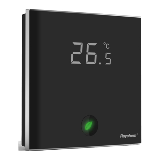
- Page 1 GREEN LEAF PROGRAMMABLE THERMOSTAT FOR ELECTRICAL FLOOR HEATING INSTALLATION INSTRuCTIONS THERMAL MANAGEMENT SOLUTIONS EN-RaychemGreenLeaf-IM-EU0209 R1...
-
Page 2: Table Of Contents
Contents 1. DesCRIPtIon ..........3 2. MoUntInG AnD InstALLAtIon ......4 Mounting the thermostat .......4 3.UsInG tHe tHeRMostAt .........9 the Display.............9 Display in manual on/off programme ....9 Display in timer programme ......10 the manual on/off programme ....11 the timer programme ........12 4. -
Page 3: Description
1. DesCRIPtIon The Raychem Green Leaf Thermostat is a Programmable Thermostat designed for Electrical Floor Heating. The thermostat is designed to control your Electrical Floor Heating in order to give you the best possible comfort and the lowest possible energy usage. -
Page 4: Mounting And Installation
2. MoUntInG AnD InstALLAtIon Mounting the thermostat Green Leaf is intended for flush mounting in a wall box. It should be positioned approximately 1.5 meters above the floor, protected from direct sunlight and draughts. All electrical conduits passing into the wall box that contain cables must also be sealed to protect the thermostat against draughts, e.g. - Page 5 Step 3: Screw the metallic support frame to the in-wall box Step 4: Install the floor sensor (mandatory for floor sensing mode or room sensing mode with floor temperature limiter). The floor sensor should be installed in a separate flexible conduit all the way to the end, covering the end of the sensor, for easy replacement and to avoid possible signal disturbance on the sensor.
- Page 6 Step 5: Connect the electrical power supply, the sensor and the cold lead of the electrical floor heating system to the Green Leaf according to the electrical diagram. If you connect heating cables exceeding 13A for constant wattage or 10A for self-regulating cables you must use a contactor with an integrated suppression device.
- Page 7 Floor Floor Power supply Heating cable Power supply Sensor Sensor 230 VAC 230 VAC 230 VAC Max. 13A* Connection via contactor - e Direct connection - e.g. single heating circuit Do not use contactor without * Max 13A for constant wattage cable, Max 10A for self-regulating cables Power supply Floor Power supply...
- Page 8 Step 6: Click the Green Leaf into the metallic support frame. Step 7: Switch on the power again Product specific information The thermostat is compatible with CeraPro, T2QuickNet, T2Blue, T2Red heating solutions. T2QuickNet T2QuickNet heating mats are approved with the Green Leaf thermostat working in floor sensor mode.
-
Page 9: Using The Thermostat
3.UsInG tHe tHeRMostAt the Display Display in manual on/off programme The following icons are visible in the Manual ON/OFF: Active sensor display • Floor sensing mode ( ) • Room Sensing mode ( • Room Sensing mode with Floor temperature limiter ( Heating display The heating display is flashing when the heating is on. -
Page 10: Display In Timer Programme
temperature The temperature on the display depends on the selected sensing mode. • Floor sensing mode => Floor temperature on the display • Room sensing mode => Room temperature on the display • Room sensing with floor temperature limiter mode => Room temperature on the display Remark: When pushing on the “... -
Page 11: The Manual On/Off Programme
time and day The actual day is displayed on the screen with the 3 letters (MON-TUE-WED-THU-FRI-SAT-SUN). The time can be set in 24H or 12AM/PM mode (see INSTALLER MENU). 4 event display The 4 events are displayed with the symbols: Event 1 Event 2 Event 3... -
Page 12: The Timer Programme
Press the “ ” or the “ ” to show the set point temperature. It will blink for 5 seconds. 1. Press the “ ” within the 5 seconds => set point = set point - 0.5°C 2. Press the “ ” within the 5 seconds => set point = set point + 0.5°C To switch from Manual ON/OFF to Timer Programme, press on the “... - Page 13 • Press on the “ ” button to set the clock and day of the week • Press on the “ ” button for 3 seconds to program the timer programme (see page 14 for more details). • Press on the “ ”...
-
Page 14: Setting The Clock
4. settInG tHe CLoCK • Press on the “ ” button to set the clock and day of the week • Press the “ ” or the “ ” to change the hours • Press on the “ ” button to validate •... -
Page 15: Programming The Timer Programme
5. PRoGRAMMInG tHe tIMeR PRoGRAMMe • Press on the “ ” button for 3 seconds to program the Timer Programme • Press the “ ” or the “ ” to choose the day (or the sequence of days) you want to program •... - Page 16 For event 1 • Press the “ ” or the “ ” to change hours of Event 1 • Press on the “ ” button to validate • Press the “ ” or the “ ” to change the minutes of Event 1 •...
-
Page 17: Installer Menu
6. InstALLeR MenU Press on the “ ” button for 5 seconds to enter the installer Menu Description Range Default setting Sensing mode Floor sensing mode Floor selection Sensing Room sensing mode mode Room sensing mode with floor temperature limiter 12 vs 24 hours 12 / 24 display... - Page 18 Description Range Default setting Room sensor Measured sensor Measured calibration temperature +/- 5°C sensor temperature Floor sensing mode: 5°C Minimum temperature 5 .. 15°C set point for the Room sensing mode: OF Floor Sensor Room sensing mode with floor temperature limiter: OF Maximum Floor sensing mode:...
- Page 19 Description Range Default setting Maximum Floor sensing mode: OF temperature Room sensing mode: 40°C set point for the Minimum temperature Room Sensor set point room sensor (installer menu 8) +5°C .. 40°C 40°C Room sensing mode with floor temperature limiter: Minimum temperature set point room sensor (installer menu 8) +5°C ..
- Page 20 Floor sensor calibration The temperature of the floor surface can differ from the temperature measured by the floor sensor due to the floor construction, the floor type and the position of the floor sensor. In order to calibrate your thermostat to this difference you can use the floor sensor calibration OFFSET in installer Menu 4.
-
Page 21: Troubleshooting
7. tRoUBLesHootInG In the event of damage or malfunction of one of the temperature sensors, the heating output cuts off (fail safe) and an error code is displayed. error Code Description Short circuit on floor sensor Open circuit on floor sensor / Missing floor sensor Short circuit on room sensor Open circuit on room sensor... -
Page 22: Technical Specification
8. teCHnICAL sPeCIFICAtIon Supply voltage 230VAC, +10%, –15%, 50Hz Power consumption (Stand-by) 3 VA Relay output 230V, maximum 13A resistive load (max. 3000W) Ambient temperature – operation 0 .. 40°C, 5-95% RH (non condensing) Ambient temperature – transport –10 .. +60°C Temperature range, floor sensor +5 .. - Page 24 Fax: +32 16 21 36 04 Fax: +0800 96 86 24 salesbelux@pentair.com salesthermaluk@pentair.com All Pentair trademarks and logos are owned by Pentair or its global affiliates. Pentair reserves the right to change specifications without prior notice. © 2013 Pentair. THERMAL MANAGEMENT SOLUTIONS...