
Related Manuals for Daikin FXDQ15P7VEB


Summary of Contents for Daikin FXDQ15P7VEB
-
Page 1: Installation Manual
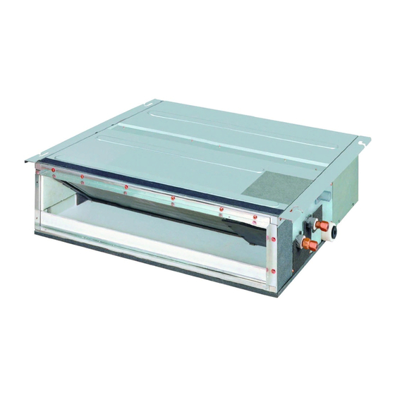
INSTALLATION MANUAL SYSTEM Inverter Air Conditioners FXDQ15P7VEB FXDQ20P7VEB FXDQ25P7VEB FXDQ32P7VEB FXDQ40P7VEB FXDQ50P7VEB FXDQ63P7VEB... - Page 2 3PW60063-3B...
-
Page 3: Table Of Contents
VRV SYSTEM Inverter Air Conditioners Installation manual • Install the air conditioner on a foundation strong enough to CONTENTS withstand the weight of the unit. 1. SAFETY PRECAUTIONS..........1 A foundation of insufficient strength may result in the equip- 2. BEFORE INSTALLATION ..........2 ment falling and causing injury. -
Page 4: Before Installation
• Do not install the air conditioner in the following locations: 2-2 ACCESSORIES Where there is a high concentration of mineral oil spray Check the following accessories are included with your unit. or vapour (e.g. a kitchen). Metal Drain Insulation Plastic parts will deteriorate, parts may fall off and water Sealing pad Name... -
Page 5: Selecting Installation Site
Is something blocking the air It may result in insufficient outlet or inlet of either the cooling. indoor or outdoor units? Are refrigerant piping length The refrigerant charge in the *300 and additional refrigerant system is not clear. charge noted down? or more more Control box... -
Page 6: Preparations Before Installation
PREPARATIONS BEFORE INSTALLATION (3) Open the installation hole. (Pre-set ceilings) • Once the installation hole is opened in the ceiling where (1) Confirm the positional relationship between the unit the unit is to be installed, pass refrigerant piping, drain and suspension bolts. (Refer to Fig. 2) piping, transmission wiring, and remote controller wiring •... -
Page 7: Indoor Unit Installation
Main unit Attach the filter to the Force main unit while pushing down on the bends. Filter Level Force Vinyl tube (4) Tighten the upper nut. REFRIGERANT PIPING WORK 〈For refrigerant piping of outdoor units, see the installation manual attached to the outdoor unit.〉 〈Execute heat insulation work completely on both sides of the gas piping and the liquid piping. - Page 8 • Refer to Table 1 for tightening torque. CAUTION Table 1 Be sure to insulate any field piping all the way to the piping connection inside the unit. Any exposed piping may cause Pipe Flare dimen- Tightening torque Flare shape condensation or burns if touched.
-
Page 9: Drain Piping Work
DRAIN PIPING WORK Large sealing pad (5) Metal clamp (1) CAUTION (accessory) (accessory) • Make sure all water is out before making the duct connection. Metal clamp (1) (accessory) (1) Install the drain piping. Tape Drain hose (2) ≤4mm (accessory) Drain socket Fig. -
Page 10: Installing The Duct
1. Remove the control box lid. Connect the remote controller INSTALLING THE DUCT and power supply (single-phase, 50 Hz 220-240 V or sin- Connect the duct supplied in the field. gle-phase, 60Hz 220V) respectively to the terminal block Air inlet side and securely connect the earth also (as shown in the figure •... -
Page 11: Electric Wiring Work
ELECTRIC WIRING WORK • The length of the transmission wiring and remote controller wiring are as follows. 9-1 GENERAL INSTRUCTIONS Length of the transmission wiring and remote controller wiring • Shut off the power before doing any work. Max. 1000m Outdoor unit –... -
Page 12: Wiring Example
10. WIRING EXAMPLE CAUTION 10-1 HOW TO CONNECT WIRINGS • When clamping the wiring, use the included clamp material (9) and (10) as shown in the Fig.17 to prevent outside pres- • Wire only after removing the control box lid as shown in sure being exerted on the wiring connections and clamp Fig. - Page 13 〈 Precautions when laying power supply wiring 〉 No. 2 system For group control or use with 2 remote controllers • Wiring of different thicknesses cannot be connected to the power supply wiring terminal block. (Slack in the power sup- Power supply single phase ply wiring may cause abnormal heat.)
-
Page 14: Field Setting And Test Run
10-2 CONTROL BY 2 REMOTE CONTROLLERS (Con- [ PRECAUTIONS ] • Crossover wiring is needed when using group control and trolling 1 indoor unit by 2 remote controllers) 2 remote controllers at the same time. • When using 2 remote controllers, one must be set to “MAIN” •... - Page 15 11-1 SETTING THE STATIC PRESSURE SELECTION 11-4 SETTINGS FOR SEPARATELY SOLD ACCESSORIES • Select the SECOND CODE NO. for the resistance of the con- nected duct. • See the instruction manuals included with separately sold (The SECOND CODE NO. is set to “01” when shipped.) accessories for the necessary settings.
-
Page 16: Wiring Diagram
12. WIRING DIAGRAM : FIELD WIRING : BLACK : ORANGE : CONNECTOR : BLUE : PINK : WIRE CLAMP : BROWN : RED : GREEN : WHITE : PROTECTIVE EARTH (SCREW) : LIVE : GREY : YELLOW : NEUTRAL A1P......PRINTED CIRCUIT BOARD S1L......FLOAT SWITCH C1...... - Page 17 NOTES...
- Page 18 NOTES...
- Page 19 NOTES...
- Page 20 4PW67403-1 01.2011...