Table of Contents
Advertisement
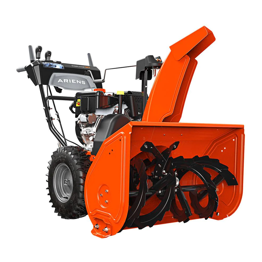
Sno-Thro
Owner/Operator Manual
921011 – Deluxe 24
921012 – Deluxe 27
921013 – Deluxe 30
921014 – Deluxe Track 24
921015 – Deluxe Track 27
921016 – Deluxe Track 30
921017 – Deluxe 24 Platinum
921018 – Deluxe 30 Platinum
921019 – Deluxe 24
921020 – Deluxe 30
®
Models
ENGLISH
FRANÇAIS
03882700E 9/09
Printed in USA
Advertisement
Table of Contents

Related Manuals for Ariens Sno-Thro 921011


Summary of Contents for Ariens Sno-Thro 921011
- Page 1 Sno-Thro Owner/Operator Manual Models 921011 – Deluxe 24 921012 – Deluxe 27 921013 – Deluxe 30 921014 – Deluxe Track 24 921015 – Deluxe Track 27 921016 – Deluxe Track 30 921017 – Deluxe 24 Platinum 921018 – Deluxe 30 Platinum 921019 –...
-
Page 2: Table Of Contents
NON-ENGLISH MANUALS Manuals in languages other than English may be obtained from your Dealer. Visit your dealer or www.ariens.com for a list of languages available for your equipment. Manuals printed in languages other than English are also available as a free download on our website: http://www.ariens.com... -
Page 3: Unauthorized Replacement Parts
4. Review recommended lubrication, maintenance and adjustments. 5. Review Limited Warranty Policy. 6. Fill out a Product Registration Card and return the card to the Ariens Company or go to www.ariens.com. GB - 3... -
Page 4: Safety
WARNING: To avoid injury to hands and feet, always disengage clutches, shut off engine, and wait for all movement to stop before unclogging or working on snow thrower. Hand contact with the rotating impeller is the most common cause of injury associated with snow throwers. -
Page 5: Safety Rules
Keep people away from unit while operating. Keep children out of work area and under watchful care of a responsible adult. OL4370 Never direct discharge towards persons or property that may be injured or damaged by thrown objects. OL0910 Stop engine, remove key, read manual before making any repairs or adjustments. - Page 6 DO NOT operate near drop-offs, ditches, or embankments. Unit can suddenly turn over if a wheel is over the edge of a cliff or ditch, or if an edge caves in. Falling snow, fog, etc. can reduce vision and cause an accident. Operate unit only when there is good visibility and light.
- Page 7 Check clutch and brake operation frequently. Adjust and service as required. All motion of drive wheels and auger/impeller must stop quickly when control levers are released. DO NOT operate on steep slopes. DO NOT clear snow across the face of slopes. Keep all movement on slopes slow and gradual.
-
Page 8: Assembly
WARNING: AVOID INJURY. Read and understand the entire Safety section before proceeding. WARNING: Dropping or tipping over boxed unit could result in personal injury or damage to unit. PACKAGE CONTENTS 921011, 012, 013, 014, 015, 016, 019, 020 4, 5 1. - Page 9 Unfold Handlebar (Figure 5) 1. Remove the lower and loosen the upper hardware on the handlebar assembly. 2. Loosen the hardware on the shift rod. 3. Put the speed selector lever in the second reverse position. (Fastest forward position for 921011, 014, 019). 4.
- Page 10 Install Discharge Chute and Discharge Chute Rod (921017, 018) (Figure 8, 9, 10 and 11) 1. Grease underside of discharge chute ring (if not already greased). 2. Remove mounting hardware from auger housing. 3. Install discharge chute over opening in the auger housing.
- Page 11 1. Chute Control Assembly 2. Hair Pin 3. Chute Rod Figure 10 9. Connect the chute lock cable to the lock arm by fitting the cable ball end into the slot on the lock arm and then insert the chute lock cable fitting into the bracket on the chute pedestal (Figure 11).
- Page 12 Check Function of Dual Handle Interlock Without the engine running, press down (engage) both clutch levers. Release attachment clutch lever. Attachment clutch should remain engaged until traction clutch lever is released, then both clutches must disengage. If they do not, contact your Dealer for repairs.
-
Page 13: Controls And Features
CONTROLS AND FEATURES SMALL DASH LARGE DASH Figure 13 1. Attachment Clutch Lever 2. Speed Selector 3. Traction Drive Clutch Lever 4. Remote Wheel Lock (012, 013, 020) 5. Deflector Remote Control (013, 016, 6. Height Adjuster Trigger (014, 015, 016) 7. - Page 14 Figure 14 1. Skid Shoe 2. Clean-Out Tool 3. Remote Discharge Chute Deflector (013, 016, 017, 018, 020) 4. Manual Discharge Chute Deflector (011, 012, 014, 019) 5. Belt Cover 6. Headlight (012, 013, 015, 016, 017, 018, 020) 7. Auger 8.
- Page 15 921011, 012, 013, 014, 015, 016, 017, 018 921019, 020 Figure 15 1. Oil Drain 2. Fuel Shut-Off Valve 3. Primer Bulb 4. Recoil Starter Handle 5. Throttle (Engine Stop) 6. Choke Control Knob 7. Ignition Key (Push/Pull) 8. Fuel Tank and Cap 9.
-
Page 16: Operation
WARNING: AVOID INJURY. Read and understand the entire Safety section before proceeding. WARNING: To avoid injury to hands and feet, always disengage clutches, shut off engine, and wait for all movement to stop before unclogging or working on snow thrower. Keep hands and feet away from auger and impeller. - Page 17 Primer Bulb Pushing the primer bulb in adds fuel for easier engine start. Refer to Starting and Shut Off on page 22. OS7320 921019, 020 OS1321 Speed Selector (012, 013, 015, 016, 017, 018, 020) Position the Speed Selector in the appropriate speed notch to control forward and reverse travel.
- Page 18 Snow Clean-Out Tool (Figure 16) WARNING: Hand contact with the rotating impeller is the most common cause of injury associated with snow throwers. Never use your hand to clean out the discharge chute. Figure 16 To clear the discharge chute: 1.
- Page 19 Discharge Chute Control (921017, 018) (Figure 18) IMPORTANT: If chute does not stay in set position, adjust as directed in Discharge Chute Control on page 28, or repair before operation. Rotate the Chute with Discharge Chute Control (Figure 18). Figure 18 IMPORTANT: DO NOT force frozen chute controls.
- Page 20 Remote Wheel Lock (921012, 013, 020) Squeeze and release the remote wheel lock control to lock the left wheel for better traction when throwing snow or to unlock the left wheel for easier steering. NOTE: The wheel lock will not release when under load.
-
Page 21: Filling Fuel Tank
FILLING FUEL TANK WARNING: AVOID INJURY. Read and understand the entire Safety section before proceeding. Fuel Shut-Off Valve IMPORTANT: The fuel shut-off valve MUST be in the closed position prior to transporting the unit. The fuel shut-off valve has two positions: Open Position: Use this position to run the unit. - Page 22 2. Pull Recoil Starter Handle. 3. If Impeller is frozen, (cannot pull Starter Handle) move unit to a heated area and thaw to prevent possible damage. 2. Check Function of Clutches If clutches do not engage or disengage properly, adjust or repair before operation. See Attachment Clutch/Brake Adjustment on page 30 and Traction Drive Clutch Adjustment on page 32.
-
Page 23: Snow Removal
2. Plug extension cord into 120V 3-wire, grounded outlet. IMPORTANT: Use only Ariens extension cord (P/N 02483100) or an equilavent cord that is rated for a minimum of 13 amps, grounded, UL listed, CSA certified and labeled as suitable for outdoor use. -
Page 24: Maintenance
Ariens Dealers will provide any service or adjustments which may be required to keep your unit operating at peak efficiency. Should engine service be required, contact an Ariens dealer or an authorized engine manufacturer's service center. WARNING: AVOID INJURY. Read and understand the entire Safety section before proceeding. -
Page 25: Check Tire Pressure
2. Add lubricant if required. Allow oil to drain to level of plug and replace plug. IMPORTANT: Use only Ariens special gear lubricant L-2 (Part Number 00008000). Gearcase filler plug may require an application of Loc-Tite® 565 thread sealant with repeated servicing. -
Page 26: Service And Adjustments
IMPORTANT: DO NOT allow grease or oil to get on friction disc, friction plate or belts. NOTE: Apply Ariens Hi-Temp Grease or equivalent to the lubrication fittings. See SERVICE PARTS on page 37. Sno-Thro should be lubricated (Figure 26) at beginning of season or every 25 operating hours. -
Page 27: Shear Bolts
1. Skid Shoe 2. Skid Shoe Hardware Figure 27 SHEAR BOLTS IMPORTANT: Use only Ariens shear bolts for replacement. Use of any other type of shear bolt may result in severe damage to unit. See SERVICE PARTS on page 37. - Page 28 REMOTE DEFLECTOR CONTROL (921013, 016, 017, 018, 020) Deflector must stay in selected position while throwing snow. If deflector does not stay in set position: 1. Tighten nut beneath control panel to increase pressure on deflector control (Figure 30). If deflector does not follow full range of travel: 1.
-
Page 29: Discharge Chute
DISCHARGE CHUTE MANUAL DEFLECTOR (921011, 012, 014, 015, 019) Deflector must stay in selected position while blowing snow. To adjust, loosen then retighten hardware to desired deflection drag force (Figure 32). Discharge Chute Adjusting Deflector Hardware Figure 32 DISCHARGE CHUTE (921011, 012, 014, 015, 019) If discharge chute does not stay in position while operating, tighten nut on carriage bolt at... - Page 30 d. Stop unit. e. Shift speed selector into first reverse speed. f. Engage the traction clutch. Unit should move backward. g. Shut off unit. 8. Adjust pivot pin on the shift rod as necessary so unit travels forward when speed selector is in first forward position and travels backward when speed selector is in first reverse position.
- Page 31 • If roller is more that 7/8 in. (22.2 mm) from frame, loosen idler adjustment nut and move idler away from the belt, tighten adjustment nut and recheck roller clearance. OS7189 Roller should be 1/2 – 7/8 in. (12.7 – 22.2 mm) from the frame when the attachment clutch is engaged.
-
Page 32: Traction Drive Clutch Adjustment
Check Attachment Brake (Figure 40) 1. With the clutch lever disengaged, brake pad must contact attachment belts. With clutch lever engaged, brake pad must be more than 1/16 in. (1.6 mm) from belts. If there is more than 1/16 in. (1.6 mm) gap, go to Check Belt Finger Clearance on page 32. -
Page 33: Attachment Drive Belt Replacement
4. To adjust traction clutch (Figure 43): a. With the traction drive clutch lever disengaged, loosen the jam nut on the cable adjuster. b. Turn the adjuster body up the cable to decrease the distance between the clutch lever and handlebar. -
Page 34: Traction Drive Belt Replacement
CAUTION: Always support Sno- Thro frame and blower housing when loosening the cap screws holding them together. Never loosen cap screws while unit is in service position. 8. Remove hex bolts securing housing to frame (two on each side). Tip housing and frame apart on pivot pin (Figure 45). - Page 35 3. Pull idler away from traction drive belt and remove belt from idler pulley, engine sheave and driven pulley (it may be necessary to turn engine pulley using recoil handle). OS7144 1. Spacer 2. Drive Plate Assembly 3. Traction Belt Idler 4.
- Page 36 OS7142 1. Hex Shaft 2. Bearing Flange 3. Speed Selector Figure 48 TRACK TENSION ADJUSTMENT (921014, 015, 016) Check the track tension by applying pressure on the track midway between the upper and rear track rollers. Deflection should be approximately 3/8 in. (9.6 mm). See Figure 49.
-
Page 37: Storage
To treat the fuel system for storage: 1. Add fuel stabilizer (Ariens p/n 00592900) according to manufacturers’ instructions. 2. Run engine for at least 10 minutes after adding stabilizer to allow it to reach the carburetor. -
Page 38: Troubleshooting
PROBLEM PROBABLE CAUSE Engine will not 1. Fuel tank is empty. crank/start. 2. Fuel shut-off valve closed. 3. Build up of dirt and residue around governor/carburetor. 4. Key Switch not in run position. 5. Electric starter not functioning. Engine stops. 1. -
Page 39: Deluxe
Model Number Description Engine Engine Gross Torque* - ft-lbs (N•m) *Engine output stated in gross torque per SAE J1940 as rated by engine manufacturer Displacement - in. (cc) High Idle - RPM (min) Electric Start Fuel Tank Capacity - qt (Liters) Chute Chute Rotation Angle Rotation Control... -
Page 40: Deluxe Track
Model Number Description Engine Engine Gross Torque* - ft-lbs (N•m) *Engine output stated in gross torque per SAE J1940 as rated by engine manufacturer Displacement - in. (cc) High Idle - RPM (min) Electric Start Fuel Tank Capacity - qt (Liters) Chute Chute Rotation Angle Rotation Control... - Page 41 Model Number Description Engine Engine Model Gross Torque* - ft-lbs (N•m) *Engine output stated in gross torque per SAE J1940 as rated by engine manufacturer Displacement - in. (cc) High Idle - RPM (min) Electric Start Fuel Tank Capacity - qt (Liters) Chute Chute Rotation Angle...
-
Page 42: Warranty
Genuine Ariens or Gravely brand service parts and accessories are warranted to be free from defects in material and workmanship for a period of 90 days after the date of purchase. An authorized Ariens dealer will repair or replace any such part or accessory free of charge, except for labor, during that period. - Page 43 Canada. In all other countries, contact place of purchase for warranty information. Disclaimer Ariens may from time to time change the design of its products. Nothing contained in this warranty shall be construed as obligating Ariens to incorporate such design changes into previously manufactured products, nor shall such changes be construed as an admission that previous designs were defective.
- Page 44 Ariens Company 655 West Ryan Street Brillion, WI 54110-1072 920-756-2141 Fax 920-756-2407 www.ariens.com Protective Floor Mat Protects floor from rust, dirt and snow melt.