Advertisement
Quick Links
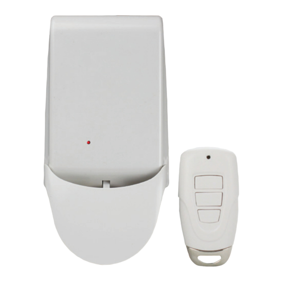
INSTALLATION INSTRUCTIONS
Universal Garage Door Remote Control
Model: MF-1
Congratulations on your purchase of the Skylink Universal Garage Door Remote
Control model MF-1. The Receiver and Remote Control is designed to work
with any garage door opener brands to give you the convenient, secure access
to your garage and home.
Section 1 - Installing the Smart Control Receiver (Continued)
4.
Drill a 1/4" (6mm) hole in the drywall for the anchor and screw (D).
5.
Drill a 3/8" (10mm) hole in the drywall for the Spring Toggles (E).
1/4" (6mm)
1/8" (10mm)
Safety Information
WARNING: This Garage Door Remote Control kit should only be installed to a garage door
opener equipped with safety infrared sensor.
WARNING: Do not let children use the garage door remote without adult supervision.
This device complies with Part 15 of the FCC Rules. Operation is subject to the following
two conditions: (1) This device may not cause harmful interference, and (2) This device
must accept any interference received, including interference that may cause undesired
operation.
NOTE: equipment has been tested and found to comply with the limits for Class B digital
device, pursuant to Part 15 of the FCC Rules. These limits are designed to provide
reasonable protection against harmful interference in a residential installation. This
equipment generates, uses and can radiate radio frequency energy and, if not installed
and used in accordance with the instructions, may cause harmful interference to radio
communications.
WARNING: Changes or modi cations not expressly approved by the party responsible for
compliance could void the user's authority to operate the product. However, there is no
guarantee that interference will not occur in a particular installation. If this equipment
does cause harmful interference to radio or television reception, which can be
determined by turning the equipment off and on, the user is encouraged to try to correct
the interference by one or more of the following measures:
Re-orient or re-locate the receiving antenna. Increase the separation between the
equipment and receiver. Connect the equipment into an outlet on a circuit different from
that to which the receiver is connected. Consult the dealer or an experienced
technician for help.
6.
Screw-in the screw to the Spring Toggles (E) with the Mounting Bracket (C).
C
E
7.
Fold the Spring Toggles (E) completely and slip it into the hole. Push it
until the wings opens.
E
E
Package Contents
B
A
D
C
E
Parts
Description
Quantity
A
Smart Control Receiver
1
B
3-Button Keychain Remote
1
C
Mounting Bracket
1
D
Screws & Anchors
3
E
Spring Toggle
1
8.
Tighten the screw (E) and ensure the mounting bracket (C) is securely installed to the wall.
C
E
9.
Screw-in the other screw (D) to secure the mounting bracket (C).
C
D
Section 1 - Installing the Smart Control Receiver
NOTE: Remove the mounting bracket from the back of the Smart Control Receiver.
NOTE: Use provided screws (D) and plastic anchors (D) for the brick wall.
NOTE: Use Spring Toggles for drywall or hollow wall with a thickness less than 1 inch.
Slightly insert (1) the mounting bracket (C) behind the wall console.
1.
2.
Measure distance (2) from the screw hole of mounting bracket to the button
of the wall console of approximately 30 - 40 mm.
C
(1)
(2)
10.
Clip in the Smart Receiver (A) on the mounting bracket (C) and push it up to lock it.
A
C
3.
Mark 2 holes on the drywall with a pencil.
C
Section 2 - Powering the Smart Control Receiver
NOTE: A 6V DC, 300mA adapter (sold separately) may be required if to operate the
Smart Control Receiver continuously.
1. Open the clip cover (1) of the Smart Control Receiver (A) with a screwdriver and insert
two AA batteries (2).
2. Position the actuator (3) on the Smart Control Receiver (A) to ensure it touches the
Wall Console button.
3.
Insert the Touch Plate (4) on the clip cover (1) of the Smart Control Receiver (A).
Close the clip cover (1) of the Smart Control Receiver (A).
4.
(2)
(1)
A
3
(4)
Advertisement

Related Manuals for SkyLink MF-1


Summary of Contents for SkyLink MF-1
- Page 1 Mounting Bracket Congratulations on your purchase of the Skylink Universal Garage Door Remote Control model MF-1. The Receiver and Remote Control is designed to work Screws & Anchors with any garage door opener brands to give you the convenient, secure access Spring Toggle to your garage and home.
- Page 2 If you have any questions, problems or missing parts, the remote to the Smart Control Receiver. please call Skylink Customer Support: 9:00am - 5:00pm EST, Monday-Friday. 1-800-304-1187 Or e-mail us at support@skylinkhome.com www.skylinkhome.com...