Table of Contents
Advertisement
Quick Links
Advertisement
Chapters
Table of Contents

Related Manuals for Global American 2808030


Summary of Contents for Global American 2808030
- Page 1 2808030 User’s Manual Mini-ITX Motherboard Version 1.0...
- Page 2 Copyrights This document is copyrighted and all rights are reserved. It does not allow any non authorization in copied, photocopied, translated or reproduced to any electronic or machine readable form in whole or in part without prior written consent from the manufacturer.
-
Page 3: Table Of Contents
Table of Contents Introduction ............1 Product Description ............. 1 Checklist ................2 2808030 Specifications ............3 Board Dimensions ............... 4 Installations ............5 Installing the CPU ............... 6 Installing the Memory ............7 Setting the Jumpers ............. 8 Connectors on 2808030............12 Appendix .............. - Page 4 This page is intentionally left blank.
-
Page 5: Introduction
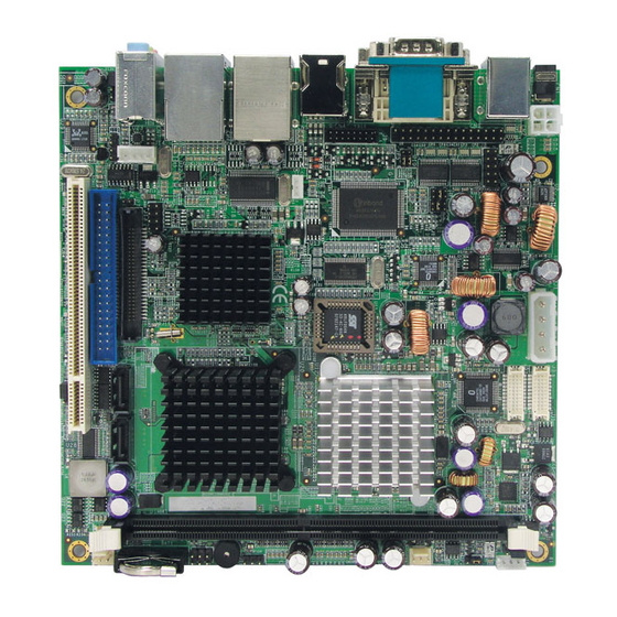
INTRODUCTION Introduction Product Description The 2808030 Mini ITX board incorporates the Mobile Intel® 910GML/915GME Express Chipset for Embedded Computing, consisting of the Intel® 910GML/ 915GME Graphic Memory Controller Hub (GMCH) and Intel® I/O Controller Hub 6-M (ICH6-M), is an optimized integrated graphics solution with a 400/533MHz front-side bus. -
Page 6: Checklist
INTRODUCTION Checklist Your 2808030 package should include the items listed below. • The 2808030 Celeron ® M Mini-ITX motherboard • This User’s Manual • 1 CD containing chipset drivers and flash memory utility • Cable kit (IDE, Serial port, Serial ATA, VGA) -
Page 7: 2808030 Specifications
INTRODUCTION 2808030 Specifications Form Factor Mini ITX CPU Type Intel Celeron M / Pentium M (on Socket 479) processor (Banias or Dothan core): - Banias: ULV Celeron M 600MHz (512KB L2 Cache), - Dothan: Zero L2 cache Celeron M 1GHz or Celeron M 373 CPU Voltage 0.700V ~ 1.708V... -
Page 8: Board Dimensions
INTRODUCTION Board Dimensions... -
Page 9: Installations
INSTALLATIONS Installations This section provides information on how to use the jumpers and connectors on the 2808030 in order to set up a workable system. The topics covered are: Installing the CPU ................ 6 Installing the Memory ..............7 Setting the Jumpers ..............8... -
Page 10: Installing The Cpu
INSTALLATIONS Installing the CPU ® The 2808030 board supports a Socket 479 processor socket for Intel ® ® Pentium M or Celeron M processors. The processor socket comes with a screw to secure the processor. As shown in the left picture below, loosen the screw first before inserting the processor. -
Page 11: Installing The Memory
INSTALLATIONS Installing the Memory The 2808030 board supports one DDR2 memory socket for a maximum total memory of 1GB in DDR2 memory type. Installing and Removing Memory Modules To install the DDR2 modules, locate the memory slot on the board and perform the following steps: 1. -
Page 12: Setting The Jumpers
INSTALLATIONS Setting the Jumpers Jumpers are used on 2808030 to select various settings and features according to your needs and applications. Contact your supplier if you have doubts about the best configuration for your needs. The following lists the connectors on 2808030 and their respective functions. - Page 13 Jumper Locations on 2808030 Jumpers on 2808030 ................Page JP1: LCD Panel Power Selection ..........10 JP8: Clear CMOS Setting ............. 10 JP7: CompactFlash Slave/Master Selection ......... 10 JP2: ATX/AT Mode Select ............10 JP3: COM3 RS232 +5V / +12V Power Setting ......10 JP4: COM4 RS232 +5V / +12V Power Setting ......
- Page 14 JP1: LCD Panel Power Selection LCD Panel Power 3.3V JP8: Clear CMOS Setting Setting Normal Clear CMOS JP7: CompactFlash Slave/Master Selection CF Setting Master Slave JP2: ATX/AT Mode Select ATX / AT ATX mode AT mode JP3: COM3 RS232 +5V / +12V Power Setting Pin # Pin # Signal Name...
- Page 15 INSTALLATIONS JP4: COM4 RS232 +5V / +12V Power Setting Pin # Pin # Signal Name Signal Name +12V RI (Default) RI (Default) COM4 Settings: Pin 1-2 short = +12V, Pin 5-6 short = +5V, Pin 3-4 Standard COM Port JP5: VGA/DVI DDCDATA and DDCCLK Signal Select VGA/DVI Select JP6: CPU FSB Selection (915GME only) 400MHz...
-
Page 16: Connectors On 2808030
INSTALLATIONS Connectors on 2808030 The connectors on 2808030 allows you to connect external devices such as keyboard, floppy disk drives, hard disk drives, printers, etc. The following table lists the connectors on 2808030 and their respective functions. Connector Locations on 2808030..........13 FAN1: CPU Fan Power Connector .......... -
Page 17: Connector Locations On 2808030
INSTALLATIONS Connector Locations on 2808030 Connector Locations on 2808030 ............Page FAN1: CPU Fan Power Connector ............14 FAN2: System Fan Power Connector ............14 CN1: DC Jack (DC in, 12V only) ............14 CN2: PS/2 Keyboard and PS/2 Mouse Connectors ......... 14 CN3: COM1 and DVI-I Connector ............ -
Page 18: Fan1: Cpu Fan Power Connector
INSTALLATIONS FAN1: CPU Fan Power Connector FAN1 is a 3-pin header for the CPU fan. The fan must be a 12V fan. Pin # Signal Name Ground +12V Rotation detection FAN2: System Fan Power Connector FAN2 is a 3-pin header for system fans. The fan must be 12V (500mA). Pin # Signal Name Ground... -
Page 19: Cn3: Com1 And Dvi-I Connector
INSTALLATIONS CN3: COM1 and DVI-I Connector Signal Name Pin # Pin # Signal Name Not Used Signal Name Pin # Pin # Signal Name DATA 2- HOT POWER DATA 2+ DATA 0- Shield 2/4 DATA 0+ DATA 4- SHIELD 0/5 DATA 4+ DATA 5- DDC CLOCK... -
Page 20: J1: Hdd Power Connector
INSTALLATIONS J1: HDD Power Connector Pin # Signal Name +12V Ground Ground Note: +12V power is provided with 2A maximum load. J2: ATX_12V Connector J2 can be used in situations where the 12V current from the ATX power is insufficient to supply needed current. Pin # Signal Name Ground... -
Page 21: J3, J5: Lvds Connectors (1St Channel, 2Nd Channel)
INSTALLATIONS J3, J5: LVDS Connectors (1st channel, 2nd channel) The LVDS connectors on board consist of the first channel (J3) and second channel (J5) and supports 18-bit or 24-bit. Signal Name Pin # Pin # Signal Name TX0- TX0+ Ground Ground TX1- TX1+... -
Page 22: J8: Com2, Com3, Com4 Serial Ports
INSTALLATIONS J8: COM2, COM3, COM4 Serial Ports Pin # Signal Name (RS-232) DCD, Data carrier detect RXD, Receive data TXD, Transmit data DTR, Data terminal ready Ground DSR, Data set ready RTS, Request to send CTS, Clear to send RI, Ring indicator No Connect. -
Page 23: J11: Power Led Connector
INSTALLATIONS J11: Power LED Connector Pin # Signal Name PLED J12: System Function Connector Signal Name Signal Name Ground PS_ON HDD Active Ground Reset ATX power on switch: Pins 1-2 HDD LED: Pins 3-4 Reset switch: Pins 5-6 J13: USB5/6 Port Pin Header Signal Name Signal Name Ground... -
Page 24: J18: Front Audio Connector
INSTALLATIONS J18: Front Audio Connector Signal Name Signal Name Rear Audio R Rear Audio L Front Audio R Front Audio L Mic In VREF Out Ground REMARKS: To use the front audio connector, the jumpers on pin 1-3 and pin 2-4 must be removed. J19: CD-In Pin Header Pin # Signal Name... -
Page 25: Appendix
APPENDIX Appendix A. I/O Port Address Map Each peripheral device in the system is assigned a set of I/O port addresses which also becomes the identity of the device. The following table lists the I/O port addresses used. Address Device Description 000h - 01Fh DMA Controller #1 020h - 03Fh... -
Page 26: Interrupt Request Lines (Irq)
APPENDIX B. Interrupt Request Lines (IRQ) Peripheral devices use interrupt request lines to notify CPU for the service required. The following table shows the IRQ used by the devices on board. Level Function IRQ0 System Timer Output IRQ1 Keyboard IRQ2 Interrupt Cascade IRQ3 Serial Port #2... -
Page 27: Watchdog Timer Configuration
APPENDIX C. Watchdog Timer Configuration The WDT is used to generate a variety of output signals after a user programmable count. The WDT is suitable for use in the prevention of system lock-up, such as when software becomes trapped in a deadlock. Under these sorts of circumstances, the timer will count to zero and the selected outputs will be driven. - Page 28 APPENDIX void copyright(void) printf("\n======== Winbond 83627EHF Watch Timer Tester (AUTO DETECT) ========\n"\ " Usage : W627E_WD reset_time\n"\ " Ex : W627E_WD 3 => reset system after 3 second\n"\ " W627E_WD 0 => disable watch dog timer\n"); //=========================================================================== void EnableWDT(int interval) unsigned char bBuf;...
- Page 29 APPENDIX //=========================================================================== // THIS CODE AND INFORMATION IS PROVIDED "AS IS" WITHOUT WARRANTY OF ANY // KIND, EITHER EXPRESSED OR IMPLIED, INCLUDING BUT NOT LIMITED TO THE // IMPLIED WARRANTIES OF MERCHANTABILITY AND/OR FITNESS FOR A PARTICULAR // PURPOSE. //=========================================================================== #include "W627EHF.H"...
- Page 30 APPENDIX //=========================================================================== void Set_W627EHF_Reg( unsigned char REG, unsigned char DATA) Unlock_W627EHF(); outportb(W627EHF_INDEX_PORT, REG); outportb(W627EHF_DATA_PORT, DATA); Lock_W627EHF(); //=========================================================================== unsigned char Get_W627EHF_Reg(unsigned char REG) unsigned char Result; Unlock_W627EHF(); outportb(W627EHF_INDEX_PORT, REG); Result = inportb(W627EHF_DATA_PORT); Lock_W627EHF(); return Result; //=========================================================================== //=========================================================================== // THIS CODE AND INFORMATION IS PROVIDED "AS IS" WITHOUT WARRANTY OF ANY // KIND, EITHER EXPRESSED OR IMPLIED, INCLUDING BUT NOT LIMITED TO THE // IMPLIED WARRANTIES OF MERCHANTABILITY AND/OR FITNESS FOR A PARTICULAR // PURPOSE.
- Page 31 We will do our best to support your products, projects and business. Address: Global American, Inc. 17 Hampshire Drive Hudson, NH 03051 Telephone: Toll Free U.S. Only (800) 833-8999 (603) 886-3900 FAX: (603) 886-4545 Website: http://www.globalamericaninc.com Support: Technical Support at Global American...