Ducati Scrambler Owner's Manual
Hide thumbs
Also See for Scrambler:
- Manual (244 pages) ,
- Owner's manual (201 pages) ,
- Instruction manual (49 pages)
Table of Contents
Advertisement
Quick Links
Advertisement
Table of Contents

Related Manuals for Ducati Scrambler


Summary of Contents for Ducati Scrambler
- Page 2 Owner’s manual ENGLISH...
- Page 3 If the motorcycle is resold, the manual must always be handed over to the new owner. This manual must be preserved with care. If it is lost or becomes damaged, contact a Ducati Dealer or authorised Service Centre without delay to obtain a new copy of the manual.
-
Page 4: Table Of Contents
Table of contents Instrument panel (Dashboard) Instrument panel Acronyms and abbreviations used in the Manual Technological Dictionary Function push-buttons Parameter setting/displaying Main functions Introduction Motorcycle speed Engine rpm indication (RPM) Safety guidelines Menu 1 functions Warning symbols used in the manual Odometer (TOT) Intended use Trip meter 1 (TRIP 1) - Page 5 ABS control uni enabling/disabling Rear brake pedal Battery voltage Gear change pedal Instrument panel back-lighting setting Adjusting the position of the gearchange pedal and (B.LIGHT) rear brake pedal Clock setting function (CLOCK) Pin Code Main components and devices Changing the PIN CODE Position on the vehicle Setting the units of measurement Tank filler plug...
- Page 6 Main maintenance operations Technical data Check brake fluid level Weights Changing the air filter Dimensions Checking brake pads for wear Fuel, lubricants and other fluids Charging the battery Engine Lubricating cables and joints Timing system Adjusting the throttle cable Performance data Checking drive chain tension Spark plugs Lubricating the drive chain...
-
Page 7: Introduction
162. Our highly skilled staff have access to special implements and appropriate equipment required to perform any servicing job at best, and use Ducati Safety guidelines original spare parts only as the best guarantee for full We would like to welcome you among Ducati interchangeability, smooth running and long life. -
Page 8: Warning Symbols Used In The Manual
maintenance. In case of any doubts, please contact a Intended use Dealer or Authorised Service Centre. Warning Warning symbols used in the manual This motorcycle is designed for on-road use, Several kinds of warnings are used as an alert of the may be used occasionally on dirt trail. - Page 9 Warning Warning Riding without a licence is illegal and is Check your state laws. Obtain insurance prosecuted by law. Always make sure you have your coverage and keep your insurance document secure licence with you when riding. Do not let with the other motorcycle documents.
-
Page 10: Rider's Training
Rider's training Jacket, trousers or riding suit must be made from leather or abrasion-resistant material and have Accidents are frequently due to inexperience. Riding, high-visibility colours and inserts. manoeuvres and braking must be performed in a different way than on the other vehicles. Important Warning Never wear loose clothing, items or accessories... - Page 11 The engine should never be started or run period. indoors. Failure to follow these instructions releases Ducati Exhaust gases are poisonous and may lead to loss of Motor Holding S.p.A. from any liability whatsoever for consciousness or even death within a short time.
-
Page 12: Refuelling
Important Important Be very careful when tackling road junctions, or Visually inspect the tyres at regular intervals for when riding in areas near exits from private grounds, detecting cracks and cuts, especially on the side car parks or on slip roads to access motorways. walls, bulges or large spots that are indicative of internal damage. -
Page 13: Carrying The Maximum Load Allowed
Never completely fill the tank when refuelling. Fuel Carrying the maximum load allowed should never be touching the rim of filler recess. Your motorcycle is designed for long-distance riding, When refuelling, avoid breathing the fuel vapours and carrying the maximum load allowed in full safety. prevent fuel from reaching your eyes, skin or clothes. -
Page 14: Dangerous Products - Warnings
Important Refer to paragraph "Tyres" on page 154. Arrange your luggage or heavy accessories in Dangerous products - warnings the lowest possible position and close to motorcycle Used engine oil centre. Important Warning Never fix bulky or heavy objects to the Prolonged or repeated contact with used engine handlebar or to the front mudguard as this would oil may cause skin cancer. - Page 15 Warning The fluid used in the brake system is corrosive. In the event of accidental contact with eyes or skin, wash the affected area with abundant running water. Coolant Engine coolant contains ethylene glycol, which may ignite under particular conditions, producing invisible flames.
-
Page 16: Vehicle Identification Number
Vehicle identification number Note These numbers identify the motorcycle model and should always be indicated when ordering spare parts. It is recommended to record the frame number (Fig. 1) of your motorcycle in the space below. Frame number Fig. 1... -
Page 17: Engine Identification Number
Engine identification number Note These numbers identify the motorcycle model and should always be indicated when ordering spare parts. It is recommended to record the number of your motorcycle's engine (Fig. 2) in the space below. Engine number Fig. 2... -
Page 18: Customisations
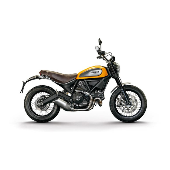
Customisations Each version is a customisation of the SCRAMBLER. The SCRAMBLER is available in four different customisations: ICON (A) URBAN ENDURO (B) FULL THROTTLE (C) CLASSIC (D) Information herein refers to Scrambler ICON. Information on any other customisation (URBAN ENDURO, FULL THROTTLE, CLASSIC) is indicated only when different from the Scrambler ICON. - Page 19 ICON Fig. 4...
- Page 20 ICON 1) Ten-spoke, light-alloy rims 2) Dedicated sticker with logo 3) Dedicated seat...
- Page 21 URBAN ENDURO Fig. 5...
- Page 22 URBAN ENDURO 1) Spoked wheels 2) Raised front mudguard 3) Sump guard 4) Dedicated sticker with logo 5) Headlight grille as standard 6) Dedicated seat 7) Handlebar crosspiece 8) Front fork guards...
- Page 23 FULL THROTTLE Fig. 6...
- Page 24 FULL THROTTLE 1) Dedicated sticker with logo 2) Tailpipe as standard (Termignoni) 3) Lowered handlebar 4) Black anodised side panels 5) Dedicated racing seat 6) Short front mudguard 7) Rear turn indicators with no splash guard...
- Page 25 CLASSIC Fig. 7...
- Page 26 CLASSIC 1) Dedicated-thickness logo 2) Aluminium spoked wheels 3) Long, satin-finished aluminium front mudguard 4) Long, satin-finished rear mudguard 5) Dedicated seat 6) Raised number plate holder...
-
Page 27: Instrument Panel (Dashboard)
Instrument panel (Dashboard) 6) FUEL WARNING LIGHT (AMBER YELLOW). Comes on when fuel is low and there are about 4 litres of fuel left in the tank. 7) TURN INDICATOR LIGHTS (GREEN). A warning light turns on and blinks when the relevant Instrument panel turn indicator is active;... - Page 28 9) ABS LIGHTS (AMBER YELLOW). This turns on to indicate that ABS is disabled or not functioning. Engine OFF / speed below 5 Km/h Light OFF Light flashing Light steady on ABS disabled with the menu func- ABS enabled, but not functioning tion "ABS"...
- Page 29 10) OVER REV / IMMOBILIZER / ANTI-THEFT SYSTEM (RED) Over rev No intervention Light OFF First threshold (N Light steady ON RPM before the limit- er kicks in) Limiter Light ON flashing Note Each calibration of the Engine Control Unit may have a different setting for the thresholds that precede the rev limiter and the rev limiter itself.
- Page 30 Fig. 8...
-
Page 31: Acronyms And Abbreviations Used In The Manual
Acronyms and abbreviations used in the Manual Antilock Braking System Controller Area Network DUCATI Data Acquisition Dashboard Engine Control Unit... -
Page 32: Technological Dictionary
Technological Dictionary Anti-lock Braking System (ABS) 9M ABS 9M system is a two-channel latest-generation system that actuates combined braking with anti lift- up function for the rear wheel so as to guarantee not only a reduced stopping distance, but also a higher stability under braking. -
Page 33: Function Push-Buttons
Function push-buttons 1) UP CONTROL SWITCH " " Button used to display and set instrument panel parameters with the position " ". 2) DOWN CONTROL SWITCH " " Button used to display and set instrument panel parameters with the position " ". -
Page 34: Parameter Setting/Displaying
Parameter setting/displaying Upon key-on, the instrument panel: turns on the display backlighting; activates the rev counter which increases from 0 to 12000 and decreases back to 0; activates the vehicle speed digits and shows a counting from 0 to 300 and then back to 0; turns on the warning lights from right to left. - Page 35 Data displayed on the main screen are as follows: 1) Engine speed. 2) Motorcycle speed. 3) MENU 1 (Odometer, Trip 1, Trip 2, Trip Fuel, Air temperature, Error warning - only if active). 4) Clock. 5) SERVICE indication (only if active). 6) Setting menu.
- Page 36 From the main screen, press button (2) on LH switch to view Menu 1 information. Odometer (TOT); TRIP 1; TRIP 2; TRIP FUEL (when function is active); T – AIR. Fig. 12...
- Page 37 The instrument panel stores Menu 1 settings in use upon KEY-OFF. On the following KEY-ON, previously stored Menu 1 pages are displayed. In case of sudden and unexpected power OFF, the instrument panel displays the default settings upon the following KEY-ON: Menu 1 default page = Odometer (TOT).
-
Page 38: Main Functions
Main functions The functions displayed in the Standard screen are the following: Main information Motorcycle speed Engine rpm indication (RPM) Menu 1 displays the following functions: - Odometer (TOT) - Trip meter 1 (TRIP 1) - Trip meter 2 (TRIP 2) - Partial fuel reserve counter (TRIP FUEL) - Ambient air temperature (AIR) - Clock... - Page 39 The functions within the Setting Menu that can be modified by the user are the following: PIN CODE (activation and modification of PIN CODE); CLOCK (clock settings); LIGHT (backlighting settings); BATTERY (battery voltage indication); UNITS (units of measurement settings); ABS (ABS control unit enabling/disabling); EXIT (to quit the Setting Menu)
-
Page 40: Motorcycle Speed
Motorcycle speed This function allows displaying the vehicle speed (km/ h or mph according to the specific application). The instrument panel receives information about the actual motorcycle speed (calculated in km/h) and displays the value increased by 5% and converted in the set unit of measurement (km/h or mph). -
Page 41: Engine Rpm Indication (Rpm)
Engine rpm indication (RPM) This function allows displaying engine rpm. Instrument panel receives rpm value and displays it. The information is displayed by the bargraph filling from the right to the left according to the engine rpm. Fig. 15... - Page 42 The thresholds before the rpm limiter are: threshold 8900 rpm (A). When the rev limiter value (B) is reached, the warning lights start flashing. Fig. 16...
-
Page 43: Menu 1 Functions
Menu 1 functions MENU 1 functions are: Odometer (TOT); Trip meter 1 (TRIP 1); Trip meter 2 (TRIP 2); Partial fuel reserve counter (TRIP FUEL); Ambient air temperature (T-AIR). By pressing button (2) it is possible to view the functions of MENU 1. Fig. -
Page 44: Odometer (Tot)
Upon Key-ON, the instrument panel always shows the Odometer indication for 10 seconds, then shows the user's settings page. Note If a string of flashing dashes " ----- " is displayed within odometer function, please contact a Ducati Dealer or Authorised Service Centre. -
Page 45: Trip Meter 1 (Trip 1)
Trip meter 1 (TRIP 1) The trip meter counts and displays the partial distance covered by the motorcycle with the set unit of measurement (km or mi). When the reading exceeds the maximum value of 9999.9 km or 9999.9 mi, distance travelled is reset and the meter automatically starts counting from 0 again. -
Page 46: Trip Meter 2 (Trip 2)
Trip meter 2 (TRIP 2) The trip meter counts and displays the partial distance covered by the motorcycle with the set unit of measurement (km or mi). When the reading exceeds the maximum value of 9999.9 km or 9999.9 mi, distance travelled is reset and the meter automatically starts counting from 0 again. -
Page 47: Partial Fuel Reserve Counter (Trip Fuel)
Partial fuel reserve counter (TRIP FUEL) The fuel trip meter counts and displays the distance covered by the motorcycle on reserve (since the low fuel light turns on) with the set unit of measurement (km or mi). When the Low Fuel Light (A) turns on, the display automatically shows the TRIP FUEL function, regardless of the currently displayed function;... - Page 48 Note If the system measurement units are changed at any moment, or if there is an interruption in the power supply (Battery Off), the distance travelled is reset and the count starts from zero (considering the newly set unit of measurement).
-
Page 49: Ambient Air Temperature (Air)
Ambient air temperature (AIR) The instrument panel displays the ambient temperature in the set unit of measurement (°C or °F), followed by the set unit of measurement and the message T-AIR. The temperature value is displayed when ranging from -39 °C to +124 °C (or -38 °F ÷ +255 °F). -
Page 50: Errors
Errors The instrument panel manages error warnings in order to allow the rider to identify any abnormal motorcycle behaviour in real time. Upon Key-ON - if there are active errors - or during normal operation of the vehicle - whenever an error is triggered - the instrument panel turns the EOBD light and Warning symbol ON and indicates the triggered error. -
Page 51: Error Warnings
3 seconds. When an error is triggered the EOBD light turns on as well. Warning When one or more errors are displayed, always contact a Ducati Dealer or authorised Service Centre. Fig. 25... -
Page 52: Displayed Errors Description
Displayed errors description Displayed error Description ENGINE Throttle position sensor malfunction Throttle motor or relay malfunction (stepper motor) Pressure sensor malfunction Engine coolant temperature sensor malfunction Injection relay malfunction Ignition coil malfunction Injector malfunction Engine rpm sensor malfunction Lambda sensor or Lambda sensor heater malfunction Motorcycle starting relay malfunction Secondary air system valve malfunction AIR –... - Page 53 Displayed error Description IMMO Generic error DSB control unit faulty communication / operation SD.STND Side stand sensor not working...
- Page 54 Error icons table WARNING LIGHT / ERROR MESSAGE ERROR ENGINE Engine control unit AIR – T. Air temperature sensor BATT. Battery voltage SPEED Speed sensor FUEL Low fuel sensor ABS control unit Can Bus OFF IMMO Immobilizer antenna Instrument panel control unit...
- Page 55 WARNING LIGHT / ERROR MESSAGE ERROR SD.STND Side stand sensor...
-
Page 56: Clock
Clock The instrument panel receives information about the time to be displayed. The instrument panel shows the time in the following format: hh (hours) : mm (minutes); with the message AM (for values ranging between 0:00 and 11:59), or PM (for values ranging between 12:00 and 12:59 and between 1:00 and 11:59). -
Page 57: High Engine Temperature
High engine temperature This Function shows an alert indicating that engine temperature reached high values: warning triggers when engine temperature exceeds 200°C. flashing HI message; steady temperature icon and set unit of measurement (°C or °F). Note When this warning is triggered, the instrument panel will not display the clock until value gets equal to or below 200°C. -
Page 58: Service Indication (Service)
Service indication (SERVICE) This indication shows the user that the motorcycle is due for service and must be taken to a Ducati Authorised Service Centre. The service warning indication can be reset only by the Authorised Ducati Service Centre during servicing. -
Page 59: Oil Service Zero Warning
"SERVICE", the Oil symbol and the message "OIL" upon each Key-ON; after 5 seconds, both the message "SERVICE" and the Oil symbol become steady until Key-OFF or until an Authorised Ducati Service Centre performs a reset. Fig. 29... -
Page 60: Desmo Service Countdown Indication
DESMO SERVICE countdown indication After OIL SERVICE zero indication first reset (at 1,000 km - 600 mi), the instrument panel activates the countdown of the kilometres (or miles) left before the following service operation: DESMO SERVICE. The kilometre count indication is shown upon Key-ON for 2 seconds;... -
Page 61: Desmo Service Indication
"SERVICE", the Desmo symbol and the message "DESMO" upon each Key-ON; after 5 seconds, both the message "SERVICE" and the Desmo symbol become steady until Key-OFF or until an Authorised Ducati Service Centre performs a reset. Fig. 31... -
Page 62: Setting Menu
Setting menu This menu allows enabling, disabling and setting some motorcycle functions. To enter the SETTING MENU it is necessary to hold button (3) for 2 seconds, with Key-ON and motorcycle actual speed (lower than or equal to) 20 km/h: within this menu, it is no longer possible to view any other function. - Page 63 For safety reasons, the setting menu can be accessed only when vehicle speed is below or equal to 20 Km/h; if this menu is accessed and vehicle speed is above 20 Km/h, the instrument panel will automatically quit it and shift back to main screen. Press buttons (1) and (2) to highlight the customisable parameters one by one: in particular, use button (2) to highlight the following item and button (1) to...
- Page 64 Fig. 33...
-
Page 65: Abs Control Uni Enabling/Disabling
ABS control uni enabling/disabling This function allows enabling or disabling the ABS system. Enter the SETTING MENU. Select the parameter to be customised (ABS), by pressing button (1) or (2). Once the desired parameter is highlighted, press CONFIRM MENU button (4). When entering the function, the currently set ABS status will be displayed: On = enabled, Off = disabled. - Page 66 Fig. 34...
- Page 67 By setting "–" (Off), the ABS will be disabled and the relevant warning light will start flashing. Important When setting the ABS OFF, Ducati recommends paying particular attention to the braking and riding style. If the ABS is in fault, "Err" is displayed when entering the function and Menu will indicate "NO RQ", since...
-
Page 68: Battery Voltage
Battery voltage This function allows you to check the motorcycle battery voltage. Enter the SETTING MENU. Select BATTERY option, by pressing button (1) or (2). Once function is highlighted, press CONFIRM MENU button (4). You open the BATTERY Menu. The information will be displayed as follows: if battery voltage is between 11.8 V and 14.9 V the reading will be displayed steady;... - Page 69 If the instrument panel is not receiving battery voltage value, a string of three dashes "- - -" is displayed. To quit the menu and go back to Setting Menu main page, select EXIT and press button (4). Fig. 38...
-
Page 70: Instrument Panel Back-Lighting Setting (B.light)
Instrument panel back-lighting setting Note (B.LIGHT) In the event of an interruption of the power supply from the Battery, when power is restored, at This function allows adjusting the backlighting the next Key-On, the backlighting will always be set intensity. by default to maximum brightness. - Page 71 Fig. 39...
-
Page 72: Clock Setting Function (Clock)
Clock setting function (CLOCK) pressing button (4) gives access to the minute setting mode; minutes start to flash; This function allows setting the clock. each time you press button (2), the digit will To view this function, enter the Setting Menu, use increase by 1 minute. - Page 73 Fig. 40...
- Page 74 To confirm (store) the new set time press button (4). The EXIT box starts flashing, press button (4) to go back to the setting menu. Note In case of battery off, when the Voltage is restored and upon next Key-On, clock will have to be set again, i.e.
-
Page 75: Pin Code
The motorcycle owner must activate (store) the PIN code; if there is already a stored PIN, contact an Authorised Ducati Dealer to have the function "reset". To perform this procedure, the Authorised Ducati Dealer may ask you to demonstrate that you are the... - Page 76 Entering the PIN CODE 3) Each time you press the button (1) the displayed number decreases by one (- 1) up to "1" and then To activate the PIN CODE function and enter your starts back from "0"; own PIN CODE you must open the SETTING MENU. 4) To confirm the number, press the button (4);...
- Page 77 Fig. 41...
- Page 78 Press button (4) to confirm the fourth and last figure: the 4-digit code starts flashing. To memorise the entered PIN, keep button (4) pressed for 3 seconds. If new settings have been saved, "MEM" will be shown and the "EXIT" box will be flashing. To quit, press button (4).
-
Page 79: Changing The Pin Code
Changing the PIN CODE 1) Press button (4), only one digit indicating "0" starts flashing; To change the existing PIN CODE and activate a new 2) Each time you press button (2) the displayed one, you must open the SETTING MENU. number increases by one (+ 1) up to "9"... - Page 80 Fig. 43...
- Page 81 After pressing button (4) to confirm the fourth and last Repeat the procedures until you confirm all the digits figure, the 4-digit code starts flashing. of the PIN CODE. Press button (4) to check the entered PIN CODE. After you press the button: if the PIN CODE is correct (D), the instrument panel shows "OK"...
- Page 82 Fig. 44...
- Page 83 Press button (4) to confirm the fourth and last figure: the 4-digit code starts flashing. To memorise the new setting, keep button (4) pressed for 3 seconds. If new settings have been saved (D), "MEM" will be shown, the "EXIT" option will be highlighted and its box will be flashing.
-
Page 84: Setting The Units Of Measurement
Setting the units of measurement This function allows changing the units of measurement of the displayed values. To manually set the units of measurement, you must enter the SETTING MENU. Select UNITS option, by pressing button (1) or (2). Once function is highlighted, press CONFIRM MENU button (4). - Page 85 Fig. 46...
- Page 86 Setting the units of measurement: Speed Km/h: if this unit is set, the following values will have the same units of measurement: This function allows changing the unit of 1) TOT, TRIP 1, TRIP 2, TRIP FUEL: Km measurement of Vehicle speed, Odometer, Trip 1, 2) Motorcycle speed: Km/h Trip 2 and Trip Fuel (when active).
- Page 87 Fig. 47...
- Page 88 Setting the units of measurement: °C: if this unit is set, the following values will have the same units of measurement: Temperature 1) T – AIR: °C This function allows you to change the units of °F: if this unit is set, the following values will have measurement of the Air Temperature indications.
- Page 89 Fig. 48...
- Page 90 DEFAULT setting This function allows setting the DEFAULT units of measurement according to the vehicle version. To gain access to this function enter the SETTING MENU, use buttons (1) and (2) to select UNITS and press button (4). Press button (1) or (2) to make the "UNIT:DF"...
-
Page 91: Light Control
Light control Low / High beam This function allows you to reduce current consumption from the battery, by managing headlight switching-on and off. Upon Key-On, low and high beams remain off (OFF). By starting the engine, the low beam will be automatically activated;... - Page 92 The low beam lights are turned on the first time it is will be interrupted and will restart when the speed pressed; from this moment, the same button can be returns below the indicated threshold. used to switch on (and off) the high beam light: if the engine is not started within 60 seconds, the low beam and high beam that were turned on will turn off.
- Page 93 Hazard function The "Hazard" function turns all four turn indicators on at the same time to signal an emergency condition. The "Hazard" function is activated by taking button (3) to position (6) for 3 seconds. Activation is only possible when motorcycle is ON (i.e. when key is turned to "ON"...
-
Page 94: Immobilizer System
Immobilizer system To further improve the anti-theft protection, the motorcycle is equipped with an engine electronic block system (IMMOBILIZER) that is automatically activated every time the instrument panel is switched off. Inside of each key handgrip there is an electronic device that modulates the signal sent by a special antenna integrated in the ignition switch upon starting. -
Page 95: Keys
Keys The motorcycle comes with 2 keys. They contain the "Immobilizer system code". Keys (B) are those for the standard use, i.e. to: start the engine; open the fuel tank plug; open the seat lock. Warning Separate the keys and use only one of the two to ride the bike. -
Page 96: Operation
Every time you turn the key from ON to OFF, the protection system activates the engine block. If also in this case you are not able to start the engine, contact an authorised Ducati service centre. Warning Strong impacts could damage the electronic components inside the key. -
Page 97: Duplicate Keys
The Ducati authorised service centre will program all new and old keys. The Ducati authorised service centre may ask to the customer to prove to be the motorcycle owner. The codes of the keys missing during the programming procedure will be erased to ensure that any lost key can not start the engine. -
Page 98: Entering Pin Code Function For Overriding Purposes
Entering PIN CODE function for overriding purposes In case of key acknowledgement system or key malfunction, the instrument panel allows the user to enter his/her own PIN CODE to temporarily restore motorcycle operation. If upon key-on an Immobilizer ERROR occurs, the instrument panel automatically activates in MENU 1 the possibility to enter the four-digit PIN CODE previously memorised with the relevant function in... - Page 99 Fig. 53...
- Page 100 (E). Important If this procedure is necessary in order to start the motorcycle, contact an Authorised Ducati Service Centre as soon as possible to fix the problem.
- Page 101 Fig. 54...
-
Page 102: Controls
Controls Position of motorcycle controls Warning This section shows the position and function of the controls used to ride the motorcycle. Be sure to read this information carefully before you use the controls. 1) Instrument panel. 2) Key-operated ignition switch and steering lock. 3) Left-hand switch. -
Page 103: Key-Operated Ignition Switch And Steering Lock
Key-operated ignition switch and steering lock It is located in front of the fuel tank and has four positions: : enables lights and engine operation; : disables lights and engine operation; : the steering is locked; : parking light and steering lock. Note To move the key to the last two positions, press Fig. -
Page 104: Left-Hand Switch
Left-hand switch 1) dip switch, two-position light selector switch: position = low beam ON (A); position = high beam ON (B); Button = high-beam flasher (FLASH) and instrument panel control (C). 2) Switch = 3-position turn indicator control: centre position = OFF; position = left turn;... -
Page 105: Clutch Lever
Clutch lever Lever (1) disengages the clutch. When clutch lever (1) is operated, the drive from the engine to the gearbox and the drive wheel is disengaged. Using the clutch properly is essential to smooth riding, especially when moving off. Important Using the clutch properly will avoid damage to transmission parts and spare the engine. - Page 106 Clutch control free play adjustment Warning A wrong adjustment can seriously affect the clutch operation and service life. A worn clutch tensions the clutch cable. Always check the free play, with cold engine, before using the vehicle. When operating the clutch lever, you must clearly feel the passage from a very low resistance to a very high resistance (operating force).
- Page 107 In case of a slipping clutch due to clutch wear, adjuster (2) on the lever must NEVER be loosened, but screwed, as described above. If the clutch is still slipping, go to a Dealer or a Ducati authorised service centre. Fig. 61...
-
Page 108: Right-Hand Switch
Right-hand switch 1) Red ON/OFF switch. 2) Black ENGINE START button. The switch (1) has three positions: A) centre: RUN OFF. In this position, the engine cannot be started and all electronic devices are OFF. B) pushed down: ON/OFF. In this position, the system can be turned ON (Key-ON) and OFF (Key- OFF). -
Page 109: Throttle Twistgrip
Throttle twistgrip The twistgrip (1) on the right handlebar opens the throttles. When released, it will spring back to the initial position (idling speed). Fig. 65... -
Page 110: Front Brake Lever
Front brake lever Pull in the lever (1) towards the twistgrip to operate the front brake. The system is hydraulically operated and you just need to pull the lever gently. The brake lever has a dial adjuster (2) for adjusting the distance between lever and twistgrip on the handlebar. -
Page 111: Rear Brake Pedal
Rear brake pedal Press pedal down with your foot to operate the rear brake (1). The control system is of the hydraulic type. Fig. 67... -
Page 112: Gear Change Pedal
Gear change pedal When released, the gear change pedal automatically returns to rest position N in the centre. This is indicated by the instrument panel N light coming on. The pedal can be moved: down = press down the pedal to engage the 1 gear and to shift down. -
Page 113: Adjusting The Position Of The Gearchange Pedal And Rear Brake Pedal
Adjusting the position of the gearchange pedal and rear brake pedal The position of the gearchange and rear brake pedals in relation to the footrests can be adjusted to suit the requirements of the rider. Adjust the pedals as follows: Gear change pedal Hold the linkage (1) and slacken the lock nuts (2) and (3). - Page 114 Rear brake pedal Loosen lock nut (4). Turn pedal stroke adjusting screw (5) until pedal is in the desired position. Tighten the lock nut (4). Operate the pedal by hand to check that there is 1.5 to 2 mm of free play before the brake bites. If not, adjust the length of the master cylinder control rod as follows.
-
Page 115: Main Components And Devices
Main components and devices Position on the vehicle 1) Tank filler plug. 2) Seat lock. 3) Side stand. 4) Rear-view mirrors. 5) Rear shock absorber adjusters. 6) Catalytic converter. 7) Exhaust silencer. Fig. 72... -
Page 116: Tank Filler Plug
Tank filler plug Opening Insert the key into the lock. Turn the key clockwise by 1/4 of a turn to release the lock. Unscrew the plug (1). Closing Tighten the plug (1) with the key inserted and push it down into its seat. Turn the key counter clockwise to the original position and remove it. -
Page 117: Seat Lock
Seat lock Opening Insert the key (1) in lock, turn clockwise while pressing down at the latch to help release the pin. Remove the seat (2) pulling it backwards until sliding it out of the front retainers. Closing Make sure all parts are correctly laid out and secured in the underseat compartment. -
Page 118: Side Stand
Side stand Important Place the motorcycle on the side stand only when you are not going to use it for short periods of time. Before lowering the side stand, make sure that the bearing surface is hard and flat. Do not park on soft or pebbled ground or on asphalt melt by the sun heat and similar or the motorcycle may fall over. -
Page 119: Usb Connection
USB connection The motorcycle is equipped with a USB 5V connection. Loads up to 1A can be connected to the USB connection. USB connection (1) is located under the seat and is protected by a flap: lift flap to use connection. Important When the engine is off and key set to ON, do not leave accessories connected to the USB socket... -
Page 120: Adjusting The Rear Shock Absorber
Adjusting the rear shock absorber The rear shock absorber has adjusters that enable you to suit the setting to the load on the motorcycle. The ring nut (A), located in the shock absorber upper side, adjusts the external spring preload. To change spring preload, turn the ring nut (A) using the supplied pin wrench, and align ring nut cam with the reference notch (B). - Page 121 Warning To turn the preload adjuster ring nut use the wrench supplied with the tool kit. Pay attention to avoid hand injuries by hitting motorcycle parts in case the wrench tooth suddenly slips on the ring nut cam while moving it. Warning The shock absorber is filled with gas under pressure and may cause severe damage if taken apart...
-
Page 122: Riding The Motorcycle
Riding the motorcycle For all mechanical parts of the motorcycle to adapt to one another and above all not to adversely affect the life of basic engine parts, it is advisable to avoid harsh accelerations and not to run the engine at high rpm for too long, especially uphill. - Page 123 During the whole running-in period, the maintenance and service rules recommended in the Warranty Card should be observed carefully. Failure to follow these instructions releases Ducati Motor Holding S.p.A. from any liability whatsoever for any 1.000 ÷ 2.500 Km 0 ÷ 1.000 Km engine damage or shorter engine life.
-
Page 124: Pre-Ride Checks
Pre-ride checks LIGHTS AND INDICATORS Make sure lights, indicators and horn work properly. Replace any burnt-out bulbs (page 90). Warning KEY LOCKS Failure to carry out these checks before riding, Ensure that tank filler plug (page 115) and seat may lead to motorcycle damage and injury to rider (page 116) are properly locked. - Page 125 When the motorcycle speed exceeds 5 km/h, the warning light switches OFF to indicate the correct operation of the ABS system. Warning In case of malfunction, do not ride the motorcycle and contact a Ducati Dealer or authorised Service Centre. Fig. 82...
-
Page 126: Abs Device
ABS device Check that the front (1) and rear (2) phonic wheels are clean. Warning Clogged reading slots would compromise system proper operation. It is recommended to disable ABS system in case of muddy road surface because under this condition the system might be subject to sudden failure. -
Page 127: Starting The Engine
Starting the engine Warning Before starting the engine, become familiar with the controls you will need to use when riding. Warning Never start or run the engine indoors. Exhaust gases are poisonous and may lead to loss of consciousness or even death within a short time. Move the ignition switch to (1, Fig. - Page 128 Warning The side stand must be fully up (in a horizontal position) as its safety sensor prevents engine starting when down. Note It is possible to start the engine with side stand down and the gearbox in neutral. When starting the motorcycle with a gear engaged, pull the clutch lever (in this case the side stand must be up).
-
Page 129: Moving Off
Moving off Warning 1) Squeeze the control lever to disengage the Avoid harsh acceleration, as this may lead to clutch. misfiring and transmission snatching. The clutch 2) Push down on gear change lever sharply with the lever should not be held in longer than necessary tip of your foot to engage the first gear. -
Page 130: Braking
Braking This avoids wheel lockup and preserves traction. Pressure is raised back up immediately and the Slow down in time, shift down to use engine brake control unit keeps controlling the brake until the risk and then brake by operating both front and rear of a lockup disappears. - Page 131 Warning When ABS is disabled, the motorcycle restores the standard brake system features; using the two brake controls separately reduces the motorcycle braking efficiency. Never use the brake controls harshly or suddenly as you may lock the wheels and lose control of the motorcycle. When riding in the rain or on slippery surfaces, braking will become less effective.
-
Page 132: Stopping The Motorcycle
Stopping the motorcycle Reduce speed, shift down and release the throttle twistgrip. Shift down to engage first gear and then neutral. Apply the brakes and bring the motorcycle to a complete stop. To switch the engine off, simply turn the key to position (2). -
Page 133: Parking
Parking Stop the motorcycle, then put it on the side stand. To prevent theft, turn the handlebar fully left and turn the ignition key to position (3). If you park in a garage or other indoor area, make sure that there is proper ventilation and that the motorcycle is not near a source of heat. -
Page 134: Refuelling
Refuelling Never overfill the tank when refuelling. Fuel should never be touching the rim of filler recess (1). Warning Use fuel with low lead content and an original octane number of at least 95. Warning The motorcycle is only compatible with fuel having a maximum content of ethanol of 10% (E10). -
Page 135: Tool Kit And Accessories
Tool kit and accessories The tool box (1) is located under the seat. The tool box includes: screwdriver; screwdriver handgrip; 3 mm Allen wrench; 4 mm Allen wrench; preload adjustment wrench; handgrip for preload adjustment wrench. To access the compartment remove the seat page 116. -
Page 136: Main Maintenance Operations
Fluid must be topped up and changed at the intervals specified in the scheduled maintenance table reported in the Warranty Booklet; please contact a Ducati Dealer or authorised Service Centre. Important It is recommended all lines be changed every four years. -
Page 137: Changing The Air Filter
Brake system If you find exceeding clearance on brake lever or pedal and brake pads are still in good condition, contact your Ducati Dealer or authorised Service Centre to have the system inspected and any air drained out of the circuit. -
Page 138: Checking Brake Pads For Wear
Friction material wear beyond this limit would lead to metal support contact with the brake disc thus compromising braking efficiency, disc integrity and rider safety. Fig. 96 Important Have the brake pads replaced at a Ducati Dealer or authorised Service Centre. Fig. 97... -
Page 139: Charging The Battery
Charging the battery Warning Have the battery removed at a Ducati Dealer or authorised Service Centre. To reach the battery, remove the seat page 116 and remove battery cover (A), after disengaging rubber band (C) and loosening screw (D). Loosen the screws... - Page 140 Charge the battery in a ventilated room. Charge the battery at 0.9 A for 5÷10 hours. Connect the battery charger leads to the battery If the motorcycle must be jump-started in an terminals: the red one to the positive terminal (+), the emergency with an external starting device, it is black one to the negative terminal (-).
- Page 141 Charging and maintenance of the battery during winter storage Your motorcycle is equipped with a connector (1), located under the seat, to which you can connect a special battery charger (2) (Battery maintenance kit part no. 69924601A - various countries; Battery maintainer kit part no.
- Page 142 Note When the motorcycle is left unused (approximately for more than 30 days) we recommend owners to use the Ducati battery charge maintainer (Battery maintenance kit part no. 69924601A - various countries; Battery maintainer kit part no. 69924601AX - for Japan, China and Australia...
-
Page 143: Lubricating Cables And Joints
Ducati Dealer or Authorised Service Centre. For trouble-free operation, periodically lubricate the ends of all Bowden cables with SHELL Advance Grease or Retinax LX2. -
Page 144: Adjusting The Throttle Cable
Adjusting the throttle cable The throttle grip must have a free play of 2 to 4 mm in all steering positions, measured on the outer edge of the twistgrip; this value is indicated in the figure as reference (A). To adjust, work the relevant adjuster (1) located on the control itself. -
Page 145: Checking Drive Chain Tension
Checking drive chain tension Important Have chain tension adjusted by a Ducati Dealer or authorised Service Centre. Make the rear wheel turn until you find the position where chain is tightest. Set the motorcycle on the side stand. With just a finger, push down the chain at the point of measurement and release. - Page 146 Warning Correct tightening of swinging arm screws (1) is critical to rider and passenger safety. Important Improper chain tension will lead to early wear of transmission parts. Check the correspondence of the positioning marks on both sides of the swinging arm to ensure a perfect wheel alignment.
-
Page 147: Lubricating The Drive Chain
Lubricating the drive chain The chain fitted on your motorcycle has O-rings that keep dirt out of and lubricant inside the sliding parts. The seals might be irreparably damaged if the chain is cleaned using any solvent other than those specific for O-ring chains or washed using steam or water cleaners. -
Page 148: Replacing The Headlight Bulbs
Replacing the headlight bulbs Important Have the lights replaced by a Ducati Dealer or an Authorised Service Centre. Warning The headlight might fog up if the motorcycle is used under the rain or after washing. Switch headlight on for a short time to dry up any condensate. - Page 149 Loosen screw (3). Tilt headlight towards the front mudguard and duly support it while loosening screws (4) on light cover (5) and remove cover. Fig. 107 Fig. 108...
- Page 150 Disconnect the connector (6). Release the clip (7). The bulb (8) has a bayonet joint: press and twist counter clockwise to remove it. Remove the bulb, then fit the new one by pressing and turning clockwise until it clicks into its seat. Note Be careful to hold the new bulb at the base only.
-
Page 151: Changing The Turn Indicator Bulbs
Changing the turn indicator bulbs To change the front/rear turn indicator bulbs, loosen the screw (1) and remove the lens (2). Fig. 111 Fig. 112... -
Page 152: Aligning The Headlight
Aligning the headlight Note Headlight features two adjusters, one for the RH beam and one for the LH beam. Check correct headlight aiming. Position the motorcycle 10 metres from a wall or a screen, the motorcycle must be perfectly upright with the tires 10 m inflated to the correct pressure and with a rider seated, perfectly perpendicular to the longitudinal... - Page 153 Aligning the headlight The vertical alignment of the headlight can be manually set by turning screw (1). Important Headlight beam adjuster screw has no limit stop. Warning The headlight might fog up if the motorcycle is used under the rain or after washing. Switch Fig.
-
Page 154: Adjusting The Rear-View Mirrors
Adjusting the rear-view mirrors Manually adjust rear-view mirror (A) to required position. Fig. 115... -
Page 155: Tubeless Tyres
0.2 ÷ 0.3 Note bar. Have the tyres replaced at a Ducati Dealer or Tyre repair or change (Tubeless tyres) authorised Service Centre. Correct removal and installation of the wheels is essential. Some parts of... - Page 156 Measure tread depth (S, Fig. 116) at the point where tread is most worn down: it should not be less than 2 mm, and in any case not less than the legal limit. Important Visually inspect the tyres at regular intervals for detecting cracks and cuts, especially on the side walls, bulges or large spots that are indicative of internal damage.
-
Page 157: Check Engine Oil Level
(2) and top up until the oil reaches the required level. Refit the plug. Important Engine oil and oil filters must be changed by a Fig. 117 Ducati Dealer or authorised Service Centre at the intervals specified in the scheduled maintenance chart reported in the Warranty Card. - Page 158 Viscosity SAE 15W-50 The other viscosity degrees indicated in the table can be used if the local average temperature is within the limits specified for that oil viscosity. 20W–40 20W–50 15W–40 15W–50 10W–40 10W–30 –10 40 C Fig. 118...
-
Page 159: Cleaning And Replacing The Spark Plugs
Cleaning and replacing the spark plugs Spark plugs are essential to smooth engine running and should be checked at regular intervals. Have the spark plug replaced by a Ducati Dealer or an authorised Service Centre. Fig. 119... -
Page 160: Cleaning The Motorcycle
Cleaning the motorcycle Important To preserve the finish of metal parts and paintwork, Do not wash your motorcycle right after use. wash and clean your motorcycle at regular intervals, When the motorcycle is still hot, water drops will anyway according to road conditions. Use specific evaporate faster and spot hot surfaces. - Page 161 Warning The headlight might fog up due to washing, rain or moisture. Switch headlight on for a short time to help and dry up any condensate. Carefully clean the phonic wheels of the ABS in order to ensure system efficiency. Do not use aggressive products in order to avoid damaging the phonic wheels and the sensors.
-
Page 162: Storing The Motorcycle
Storing the motorcycle Periodically carry out the required checks and renew parts as necessary, using Ducati original spare parts, If the motorcycle is to be left unridden over long in compliance with the regulations in the country periods, it is advisable to carry out the following concerned. -
Page 163: Scheduled Maintenance Chart
Scheduled maintenance chart Scheduled maintenance chart: operations to be carried out by the dealer List of operations and type of interven- km. x1,000 Time tion (months) mi. x1,000 0.6 22.5 [set mileage (km/mi) or time interval *] Reading of the error memory with DDS and check of software version update on control units Check the presence of any technical updates and recall campaigns... - Page 164 List of operations and type of interven- km. x1,000 Time tion (months) mi. x1,000 0.6 22.5 [set mileage (km/mi) or time interval *] Check the proper tightening of brake calliper bolts and brake disc flange screws Check front and rear wheel nuts tightening Check frame-to-engine fasteners tightening Check wheel hub bearings Check and lubricate the rear wheel shaft...
- Page 165 List of operations and type of interven- km. x1,000 Time tion (months) mi. x1,000 0.6 22.5 [set mileage (km/mi) or time interval *] Visually check the fuel lines Check rubbing points, clearance, freedom of movement and positioning of hoses and electric wiring in view Lubricate the levers at the handlebar and pedal controls Check tyre pressure and wear Check the battery charge level...
- Page 166 List of operations and type of interven- km. x1,000 Time tion (months) mi. x1,000 0.6 22.5 [set mileage (km/mi) or time interval *] Check spoked wheels as specified in the workshop man- * Service operation to be carried out in accordance with the specified distance or time intervals (km, miles or months), whichever occurs first...
-
Page 167: Scheduled Maintenance Chart: Operations To Be Carried Out By The Customer
Scheduled maintenance chart: operations to be carried out by the Customer km. x1,000 List of operations and type of intervention [set mileage (km/mi) or time mi x1,000 interval *] Months Check engine oil level Check brake fluid level Check tyre pressure and wear Check final drive chain tension and lubrication Check brake pads. -
Page 168: Technical Data
Technical data Weights Overall weight (in running order with 90% of fuel - 93/93/EC): 186 kg (ICON); 192 kg (URBAN ENDURO); 186 kg (FULL THROTTLE); 186,5 kg (CLASSIC); Overall weight (without fluids and battery): 170 kg (ICON); 176 kg (URBAN ENDURO); 170 kg (FULL THROTTLE);... -
Page 169: Dimensions
Dimensions 855±20 mm 300±20 mm 170±20 mm 1450±20 mm 2100±20 mm / 2140±20mm Fig. 120... - Page 170 Whenever values are indicated with a letter, please refer to the following list: A) Scrambler ICON B) Scrambler URBAN ENDURO C) Scrambler FULL THROTTLE D) Scrambler CLASSIC...
-
Page 171: Fuel, Lubricants And Other Fluids
Fuel, lubricants and other fluids FUEL, LUBRICANTS AND OTHER TYPE FLUIDS Unleaded fuel with a minimum octane rat- Fuel tank, including a reserve of 4 cu. dm 13.5 cu. dm (litres) ing of RON 95. (litres) Oil sump and filter SHELL - Advance 4T Ultra 3.4 cu. -
Page 172: Engine
Engine Longitudinal 90º "L" twin cylinder, four-stroke. Bore, mm: 88 Stroke, mm: 66 Total displacement, cu. cm: 803 Compression ratio: 11±0.5:1 Max. power at crankshaft (95/1/EC): 55 kW - 74 HP at 8,250 rpm Max. torque at crankshaft (95/1/EC): 68 Nm - 6.9 Kgm at 5,750 rpm. Maximum rpm: 9,200. -
Page 173: Timing System
Timing system DESMODROMIC system with two valves per cylinder controlled by four rocker arms (two opening and two closing ones) and one overhead camshaft. This system is driven by the crankshaft through spur gears, belt rollers and toothed belts. Desmodromic timing system 1) Opening (or upper) rocker arm;... -
Page 174: Performance Data
Fuel supply: 95-98 RON. Important Warning Failure to follow these instructions releases Ducati Motor Holding S.p.A. from any liability The motorcycle is only compatible with fuel whatsoever for any engine damage or shorter engine having a maximum content of ethanol of 10% (E10). -
Page 175: Transmission
Hydraulically operated by a control lever on handlebar Transmission right-hand side. Wet clutch controlled by the lever on left-hand side Brake calliper make: BREMBO. of the handlebar. Type: M4.3 pistons. Drive is transmitted from engine to gearbox primary Friction material: TT 2182 FF. shaft via spur gears. -
Page 176: Frame
Trail in mm: 112 Warning If the rear sprocket needs replacing, contact a Wheels Ducati Dealer or authorised Service Centre. Ten-spoke light alloy wheel rims (ICON, FULL If improperly replaced, this component could THROTTLE). seriously endanger your safety, as well as the... -
Page 177: Exhaust System
Matt Black wheel rims PEHADUR EINBRENN-LACK swinging arm. The whole system gives the VPCH03352 (Peter Lacke) motorcycle excellent stability. Suspension travel: 61 mm. Scrambler URBAN ENDURO Rear wheel travel: 150 mm. Wild Green Primer code DS20054 (LECHLER); Exhaust system Varnish code MC060013 (LECHLER);... - Page 178 Charcoal black frame AKZO NOBEL code MY/ 2/9611AV Matt Black wheel rims PEHADUR EINBRENN-LACK VPCH03352 (Peter Lacke) Scrambler CLASSIC Orange Sunshine Primer code DS20052 (LECHLER); Base coat code 2909041 (LECHLER); Clear coat code 96230 (LECHLER); Charcoal black frame AKZO NOBEL code MY/...
-
Page 179: Electric System
Electric system Note Basic electric items are: For bulb replacement instructions, please see Headlight: the paragraph "Replacing the high and low beam low/high beam: H4 bulb (12V – 60/55W); bulbs". parking light: no. 1 LED (3.1W — 13.5V) Fuses Electrical controls on handlebars. Turn indicators: There are seven fuses that protect the electric front: 12V RY10W bulb;... - Page 180 The fuse box (A, Fig. 122) is located under the seat so it is necessary to remove the seat and the battery cover to reach it. To expose the fuses, lift the box protective cover. Mounting position and ampere capacity are marked on box cover. Fuse box key El.
- Page 181 The main fuse (C) is positioned on the solenoid starter (D). Remove the fuse cap (E) to reach it. A blown fuse can be identified by breakage of the inner filament (F). Important Switch the ignition key to OFF before replacing the fuse to avoid possible short-circuits.
- Page 182 Injection/electric system diagram key Horizontal lambda sensor Horizontal spark plug Front stop switch Horizontal coil Clutch switch Vertical spark plug Right-hand switch Vertical coil Key switch Horizontal injector Left-hand switch Vertical injector Fuse box Potentiometer drive (TPS) Mobile phone power socket Secondary air actuator Bluetooth Module MAP sensor...
- Page 183 RH heated handgrip Front left turn indicator Headlight Front right turn indicator Horn Wire colour coding B Blue W White V Violet Bk Black Y Yellow R Red Lb Light blue Gr Grey G Green Bn Brown O Orange P Pink Note The electric system wiring diagram is at the end of this manual.
-
Page 184: Routine Maintenance Record Routine Maintenance Record
Routine maintenance record Routine maintenance record NAME MILEAGE (KM) DATE DUCATI SERVICE 1000 12000 24000 36000 48000 60000... - Page 186 Y/Gr P/Bk Bk/G P/Bk R/Bk Bk/G W/Bk Gr/R Bk/G W/Bk Bk/G Bk/G 2 3 4 5 Bn/W Bn/W Bn/W Bn/Bk Bn/W Bn/W Lb/W Bk/V Bk/V Bn/W Bn/G Bn/W Bk/V Bn/W Gr/B Gr/G Bk/G 1 2 3 4 Gr/R Scrambler...