
Related Manuals for Liebert CHALLENGER 3000


Summary of Contents for Liebert CHALLENGER 3000
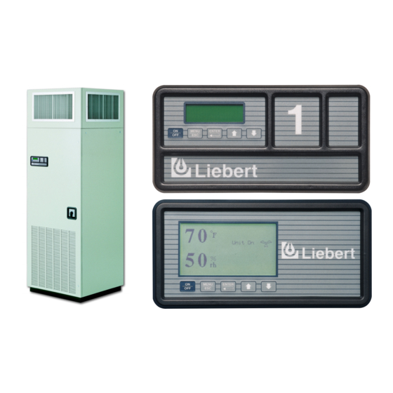
- Page 1 Liebert Challenger 3000 ™ Operation & Maintenance Manual - 3 & 5 Ton, 50 & 60Hz Precision Cooling For Business-Critical Continuity...
-
Page 3: Table Of Contents
............1 NTRODUCTION System Descriptions . - Page 4 3.7.1 Setup Operation ............. 20 3.7.2 Select Options .
- Page 5 4.4.2 Sequential Load Activation Control ..........34 Additional Features .
- Page 6 Humidifier..............53 6.5.1 Infrared Humidifier .
- Page 7 Advanced microprocessor (A) control for Challenger 3000 ....... . 4...
-
Page 9: Introduction
Compressorized systems may be a self-contained system – with the compressor in the Challenger 3000 unit, or a split system – with the compressor in the separate condensing unit. These systems may be air, water, or glycol cooled, depending on the heat rejection method selected. -
Page 10: Start-Up Procedure
Locate the start-up form supplied with your unit documents. Complete the form during your start-up and mail it to Liebert when start-up is completed. Contact your Liebert supplier if you have any ques- tions or problems during your unit installation, start-up, or operation. -
Page 11: Operation With Advanced Microprocessor Controls
PERATION WITH The advanced microprocessor (A) control for your Liebert Challenger 3000 unit features an easy-to- use menu driven LCD display. The menus, control features, and circuit board details are described in this section. For more control details, refer to 4.0 - System Performance with Advanced Micro- processor Controls, and for more alarm information, refer to 5.0 - Alarm Descriptions. -
Page 12: Figure 2 Advanced Microprocessor (A) Control For Challenger 3000
Figure 2 Advanced microprocessor (A) control for Challenger 3000 72°F 50%RH Normal Display Cooling Dehumidifying No Alarms Present Status Alarm Data Active Alarms Operating Status Alarm History Log Run Hours Log Alarm Active Operating Alarms Status History Log No Alarms Present... -
Page 13: Status Display
Status Display The display normally shown includes the present room temperature, humidity, active status func- tions (cooling, heating, dehumidifying, humidifying), and active alarms. If no keys are pressed within 5 minutes, the system automatically returns to the Status Display. The Status Display may also be selected from the Main Menu. -
Page 14: Run Hours Log
2.4.4 Run Hours Log The total operating hours of all major components in the unit can be monitored from the display and are retained in nonvolatile memory. Run times are available for the following: • Compressor • GLYCOOL Coil (or CW Coil as used on Dual Cooling Unit) •... -
Page 15: Setup System
The message “Restart Delay -- Please Wait” will be displayed when the system is in the auto restart mode. Liebert suggests programming multiple unit installations with different auto restart times. -
Page 16: Table 2 Setup Functions, Default Values And Ranges
Table 2 lists the setup functions, their factory default values and the allowable programming ranges. Table 2 Setup functions, default values and ranges Function Default Cold Start Time Delay* Restart Time Delay Infrared Fill Rate Chilled/Hot Water Coil Flush C/F Degrees *Factory set to 0 for water cooled, glycol, and GLYCOOL units. -
Page 17: Table 5 Alarm Default Time Delays
Select Control Type • Intelligent (Chilled Water only) • Proportional (all unit types) • Tunable PID (Chilled Water or SCR Reheats only) The type of system control method used by the microprocessor can be selected from the front panel. The default setting is Intelligent, which approximates the actions that a human operator would take to maintain precise, stable control. - Page 18 Enable Alarms—Each individual alarm can be selected to be ENABLED (annunciated audibly, visu- ally, and communicated to a Site Products System) or DISABLED (ignored). Enable Common Alarm—Each individual alarm can be selected to energize or to not energize the common alarm relay. If the energize common alarm function is set to YES, the relay is energized immediately as the alarm is annunciated and de-energized when the alarm condition goes away (only after the alarm has been recognized).
- Page 19 Analog Setup For installation of analog sensors, see 4.5.1 - Connecting the Analog Sensors. After selecting a compatible sensor and properly wiring it to the terminals, set up the control to mon- itor the sensor as follows: Slope—The slope is a multiplier used to scale the input signal. The slope can be positive (rising) or negative (falling) and can range from 0 (resulting in a horizontal line) to ±999.
-
Page 20: Run Diagnostics
2.5.3 Run Diagnostics By selecting Run Diagnostics, maintenance personnel can check system inputs, outputs, and complete a test of the microcontroller circuit board, all from the front panel. Review of the system inputs and the microcontroller test can be done without interrupting normal operation. To test the system out- puts, the normal system control is temporarily suspended. -
Page 21: Change Passwords
2.5.4 Change Passwords The display prompts you to enter a three digit password when making changes. The system includes two (2) passwords, one for setpoints and one for setup. The system allows the passwords to be changed by first entering the present password, factory set as “123” for setpoints and “321” for setup. The pass- word function provides system security, so only personnel authorized to make changes should know the passwords. -
Page 22: Non-Volatile Memory
2.8.2 Non-Volatile Memory All critical information is stored in nonvolatile memory. Setpoints, setup parameters, and component run hours are kept inside the microcontroller in EEPROM. Information retained for the alarm history is kept in non-volatile RAM. 2.8.3 DIP Switches Equipment options are selected and enabled using DIP switches 1 through 7. These are located at the upper left of the control board and are labeled SW1. -
Page 23: Operation With Advanced Microprocessor With Graphics Control
PERATION WITH The advanced microprocessor with graphics (G) control for your Liebert Challenger 3000 unit features an easy to use, menu driven LCD Graphics Display. The menus, control features, and circuit board details are described in this section. For more details on the control refer to 4.0 - System Perfor- mance with Advanced Microprocessor Controls;... -
Page 24: Figure 4 Advanced Microprocessor With Graphics Control Menu
Figure 4 Advanced microprocessor with graphics control menu Normal Display View/Set View/Set Operating Control Alarms Status Setpoints Operating Status View/Set Setpoints Compressor Cooling % Temperature Setpoint Heating % Sensitivity Setpoint GLYCOOL %** Humidity Setpoint Chilled Water Valve %** Sensitivity Dehumidification % High Temperature Alarm Humidification % Low Temperature Alarm... -
Page 25: Status Display
Status Display The normal status screen is divided into two sections, a right half and a left half. The left half displays the return air temperature and humidity readings in large characters. NOTE The display can also be set to display the temperature and humidity setpoints. See 3.7.7 - Set Status Display. -
Page 26: Setup Alarms
3.4.3 Setup Alarms The list of alarms may be reviewed using the UP/DOWN keys. Any alarm may be selected to have it's parameters modified by pressing the ENTER key. All alarms have a time delay and alarm type parameter. The high/low temperature and humidity alarms also have a programmable Trip Point. The Trip Point is the point at which the alarm is activated. -
Page 27: Setup Custom Alarms
3.4.4 Setup Custom Alarms Selecting SETUP CUSTOM ALARMS will step to the following menu: • SETUP CUSTOM ALARM TEXT • CHANGE CUSTOM TEXT 1 • CHANGE CUSTOM TEXT 2 • CHANGE CUSTOM TEXT 3 • CHANGE CUSTOM TEXT 4 The custom alarm messages can be selected from a list of standard messages or you can write your own messages. -
Page 28: Operating Status
Operating Status The Operating Status is intended to provide the user with displayed information about what the con- trol is calling for the system to do. NOTE There may be some time lapse before a specific component matches the displayed number. For example: The display indicates the chilled water valve is 68% open. -
Page 29: Table 9 Setup Functions, Default Values And Ranges
The message “Restart Delay -- Please Wait” will be displayed when the system is in the auto restart mode. Liebert suggests pro- gramming multiple unit installations with different auto restart times. -
Page 30: Select Options
3.7.2 Select Options The following table is a list of options which should match the options installed with your unit and should not need to change during normal operation. Table 10 Unit options Option Selection Reheat YES or NO Humidity YES or NO Dehumidify YES or NO... -
Page 31: Select Humidity Sensing Mode
3.7.6 Select Humidity Sensing Mode The user may select between RELATIVE (direct) and ABSOLUTE (predictive) humidity control. If relative is selected, the RH control is taken directly from the RH sensor. If absolute is selected, the RH control is automatically adjusted as the return air temperature deviates from the desired temper- ature setpoint. -
Page 32: Show Inputs
3.8.1 Show Inputs With the unit on and the fan running, the input state for the following devices may be displayed: • Air Sail Switch: normally off unless Loss of Air Alarm is active • Custom Alarm #1: normally off unless this alarm is active •... -
Page 33: Dip Switches
3.8.4 DIP Switches The DIP switch settings can be reviewed from the display panel. Changing the DIP switches requires opening the front panel for access to the DIP switches on the microprocessor control board. NOTE Power MUST be cycled off, then on, from the unit disconnect switch for the control system to update the DIP switch settings (except for switch 8). -
Page 34: Analog/Digital Inputs
3.11 Analog/Digital Inputs Selecting ANALOG/DIGITAL INPUTS steps to the following menu: • READ ANALOG INPUTS • SETUP ANALOG INPUTS • READ DIGITAL INPUTS • SETUP DIGITAL INPUTS 3.11.1 Read Analog Inputs The four (4) analog sensor inputs can be monitored from the display. The inputs are filtered, then dis- played along with the text label assigned during setup. -
Page 35: 3.12.1 View 24 Hour Run Time History
3.12.1 View 24 Hour Run Time History The history of each load for every hour during the past 24 hours is displayed in the run hour history. The percentage of each hour that the load was on is displayed from 0 to 100% in increments of 5% or 3 minutes. -
Page 36: 3.13.2 Nonvolatile Memory
3.13.2 Nonvolatile Memory All critical information is stored in nonvolatile memory. Setpoints, setup parameters, and component run hours are kept inside the microcontroller in EEPROM. Information retained for data logging, 24 hour component run hour graphs, alarm history, and the water detection floor plan is kept in non- volatile RAM. -
Page 37: System Performance With Advanced Microprocessor Controls
YSTEM ERFORMANCE WITH This section provides details on how your Challenger 3000 unit responds to user inputs and room con- ditions. Refer to this section when you need specific information. This section includes details on con- trol. Temperature Control 4.1.1... -
Page 38: Cooling Operation
4.1.3 Cooling Operation 1-Step Cooling, Compressorized Direct Expansion (DX) Systems Cooling activates when the temperature control calculates a requirement for cooling of 100%. It is deactivated when the cooling requirement drops below 50%. The hot gas bypass is energized on a call for cooling unless there is also a call for dehumidification. -
Page 39: Heating Operation
4.1.4 Heating Operation Electric Reheat The two heat stages are activated when the temperature control calculates a requirement of 50% and 100%, respectively. Each stage is deactivated when the heat requirement is 25% less than the activa- tion point. Hot Water Reheat The solenoid valve opens when the requirement for heating is 100% and closes when the requirement drops below 50%. -
Page 40: Humidification Operation
4.2.4 Humidification Operation System Activation The humidifier (infrared or steam) is activated when the humidity control calculates a requirement of 100% humidification, and deactivated when the requirement falls below 50%. Control Types 4.3.1 Proportional Control This is a standard control method that maintains the room at a temperature proportional to the load. The temperature maintained increases as the room load increases. -
Page 41: Intelligent Control (Chilled Water Only)
A suggested tuning procedure is as follows: 1. Initially adjust the integral and derivative settings to 0%/ degree-min and 0% /degree/min. 2. Starting with 20% /degree, adjust the proportional setting in small increments (10% steps) until the control sustains a constant hunting action (the temperature swings are approximately the same amplitude from one peak to the next). -
Page 42: Load Control Features
Input #3 (+) Input #3 (–) Input #4 (+) Input #4 (–) Consult your Liebert supplier for a field installation kit to add these connections after unit delivery, if required. Table 15 Additional connections available after unit delivery Input #1 4–20 mA... -
Page 43: Water Detection Display
Figure 5 Analog input jumpers 4.5.2 Water Detection Display The water detection display is designed to graphically display the location of water under a raised floor when connected to an LT750 water detection system. The graphical floor plan screen shows a 30 x 16 grid. - Page 44 This strip is provided on units ordered with analog inputs. (If this strip is not installed, there is a field installation kit available from your Liebert representative.) The 4-20 mA output of the LT750 must be connected to the first analog input, as shown.
-
Page 45: Communications
The control system uses a two-wire, RS-422 channel to communicate with remote monitoring systems via Liebert Site Products. This communication, directly out of the control, uses a proprietary protocol. Your unit can have a variety of different Site Product devices wired to this port depending on the monitoring system you are using. -
Page 46: Alarm Descriptions
When a new alarm occurs, it is displayed on the screen and the audible alarm is activated. If commu- nicating with a Liebert Site Product, the alarm is also transmitted. The display will also show a mes- sage to “PRESS ENTER KEY TO SILENCE” the alarm. After the alarm is silenced, the display will return to the Normal Status Display. -
Page 47: Compressor Overload
5.1.2 Compressor Overload An optional tri-block overload device can be used for the compressor. Compressor overload may be manual or automatic reset, depending on your model. Overload is located at the electric connection box on the compressor. 5.1.3 Custom Alarms Custom alarm messages are programmed at the LCD display. -
Page 48: High Temperature And Low Temperature (Simultaneously)
If the unit has lost power, or the disconnect switch was turned off before the unit ON switch was pressed (to turn the unit Off), this local alarm will occur when power is restored to the unit. A Liebert remote monitoring unit (optional) will immediately indicate loss of power. -
Page 49: Short Cycle
An optional flow switch is required for this alarm. Check for service valves closed, pumps not working, etc. 5.2.2 Smoke Detected Smoke is detected in the return air by an optional Liebert Smoke Detector. Check for source of smoke or fire, and follow appropriate emergency procedures. 5.2.3 Standby GC Pump On The primary pump has failed, and the standby pump is activated (glycol cooled and GLYCOOL units only). -
Page 50: Component Operation And Maintenance
OMPONENT PERATION AND System Testing 6.1.1 Environmental Control Functions The performance of all control circuits can be tested by actuating each of the main functions. This is done by temporarily changing the setpoints. Cooling To test the cooling function, set the setpoint for a temperature of 10°F (5°C) below room temperature. A call for cooling should be seen and the equipment should begin to cool. -
Page 51: Figure 7 Liebert Leak Detection Units
Liebert environmental unit or at a monitoring panel. Run wires to the Liebert unit and connect them to terminals 24 and 51, 55 or 56. Use NEC Class 2, 24V wiring. The sensor contains a solid state switch that closes when water is detected by the twin sensor probes. The sensor is hermetically sealed in all thread PVC nipple and is to be mounted where water problems may occur. -
Page 52: Filters
Liebert environmental unit or at a monitoring panel. Run wires to the Liebert unit and connect them to terminals 24 and 51, 55 or 56. The sensor utilizes Liebert's LT500Y leak detection cable. The kit is offered with five different lengths of cable sized specifically for the type of Liebert Environmental unit (see matrix below). -
Page 53: Blower Package
Blower Package Periodic checks of the blower package include: belt, motor mounts, fan bearings, and impellers. 6.3.1 Fan Impellers and Bearings Fan impellers should be periodically inspected and any debris removed. Check to see if they are tightly mounted on the fan shaft. Rotate the impellers and make sure they do not rub against the fan housing. -
Page 54: Refrigeration System
Refrigeration System Each month, the components of the refrigeration system should be inspected for proper function and signs of wear. Since, in most cases, evidence of malfunction is present prior to component failure, peri- odic inspections can be a major factor in the prevention of most system failures. Refrigerant lines must be properly supported and not allowed to vibrate against ceilings, floors or the unit frame. -
Page 55: Thermostatic Expansion Valve
6.4.4 Thermostatic Expansion Valve Operation The thermostatic expansion valve performs one function. It keeps the evaporator supplied with enough refrigerant to satisfy load conditions. It does not effect compressor operation. Proper valve operation can be determined by measuring superheat. If too little refrigerant is being fed to the evaporator, the superheat will be high;... -
Page 56: Air Cooled Condenser
6.4.6 Air Cooled Condenser Restricted airflow through the condenser coil will reduce the operating efficiency of the unit and can result in high compressor head pressure and loss of cooling. Clean the condenser coil of all debris that will inhibit air flow. This can be done with compressed air or commercial coil cleaner. -
Page 57: Water/Glycol Cooled Condensers
6.4.7 Water/Glycol Cooled Condensers Coaxial Condenser Each water or glycol cooled module has a coaxial condenser which consists of a steel outside tube and a copper inside tube. Coaxial condensers do not normally require maintenance or replacement if the water supply is clean. If your system operates at high head pressure with reduced capacity, and all other causes have been eliminated, the coaxial condenser may be obstructed and needs to be replaced. -
Page 58: Figure 11 Metrex Valve Adjustment
High Pressure Valve - 350 PSIG System (2413 kPa) for 3 Ton Units (Metrex Valve) Adjustment—The valve may be adjusted using a 1/8" diameter rod. Turn adjusting collar nut coun- terclockwise to raise head pressure. Turn it clockwise to lower head pressure. Rotation directions are as viewed from top of valve spring housing. -
Page 59: Compressor Functional Check
6.4.8 Compressor Functional Check The following diagnostic procedure should be used to evaluate whether the compressor is working properly. 1. Proper voltage to the unit should be verified. 2. The normal checks of motor winding continuity and short to ground should be made to determine if the inherent overload motor protector has opened or if an internal motor short or ground fault has developed. - Page 60 Use long rubber gloves in handling contaminated parts. Compressor Replacement Procedure Replacement compressors are available from your Liebert supplier. They will be shipped in a reusable crate to the job site as required by the service contractor. Upon shipping a replacement compressor, the service contractor will be billed in full for the compres- sor until the replacement has been returned to the factory.
-
Page 61: Humidifier
Humidifier 6.5.1 Infrared Humidifier During normal humidifier operation, deposits of mineral solids will collect in the humidifier pan. This should be cleaned out periodically to ensure efficient operation. Each water supply has different char- acteristics, so the time interval between cleanings must be determined locally. A monthly check (and cleaning if necessary) is recommended. -
Page 62: Steam Generating Humidifier
Autoflush Infrared Humidifier Cleaning System NOTE To operate properly, the Autoflush Humidifier requires a water source that can deliver at least 1 gpm (0.063 l/s) with a minimum pressure of 20 psig (138 kPa). The autoflush system will periodically flush the humidifier pan with water to prevent the buildup of water minerals due to saturation. - Page 63 Operation 1. During start-up, when the humidity control calls for humidification, the fill valve opens and allows water to enter the canister. When the water level reaches the electrodes, current flows and the water begins to warm. The canister fills until the amperage reaches the setpoint and the fill valve closes.
-
Page 64: Table 20 Humidifier Canister Part Numbers
Replacing the Canister Over a period of operation, the humidifier electrodes become coated with mineral solids. This coating insulates the electrodes and decreases the current flow. To maintain humidifier capacity, the water level slowly rises to expose fresh electrode. Eventually, the entire electrode becomes coated and the water level reaches the top. -
Page 65: Figure 14 Canister Replacement
Liebert supplier. The pot marked “SEC” controls the duration of the drain cycle. The pot is clearly marked in seconds. -
Page 66: Troubleshooting
ROUBLESHOOTING Use this section to assist in troubleshooting your unit. Also refer to 5.0 - Alarm Descriptions. Sug- gestions are grouped by product function for convenience. WARNING Only qualified personnel should perform service on these units. Lethal voltage is present in some circuits. -
Page 67: Table 23 Compressor And Refrigeration System Troubleshooting
Table 23 Compressor and refrigeration system troubleshooting Symptom Compressor will not start Compressor will not operate, contactor not pulling in Compressor will not operate, contact not pulling in Compressor contactor pulled in but compressor will not operate Compressor runs for three minutes then stops;... - Page 68 Table 23 Compressor and refrigeration system troubleshooting (continued) Symptom Flooding Low compressor capacity or inability to pull down system Compressor noisy Pipe rattle Compressor running hot Compressor cycles intermittently Compressor cycles continually Compressor motor protectors tripping or cycling Compressor cycles on locked rotor Motor burnout Possible Cause Defective or improperly set expansion...
-
Page 69: Table 24 Dehumidification Troubleshooting
Table 24 Dehumidification troubleshooting Symptom No dehumidification Table 25 Glycol pump troubleshooting Symptom Suddenly stops pumping Suddenly slow pumping Excessive leakage around the pump shaft while operating Performance poor Noisy operation Table 26 Infrared humidifier troubleshooting Symptom No humidification Possible Cause Control not calling for dehumidification Compressor contactor not pulling in... -
Page 70: Table 27 Steam Generating Humidifier Troubleshooting
Table 27 Steam generating humidifier troubleshooting Symptom Foaming False canister full indication Shorts or loose connections Main 24 VAC fuse or circuit breaker trips Faulty circuit board Faulty solenoid Main fuses blow approximately 15 seconds Conductivity too high after unit is activated Mineral deposits obstruct drain valve Main fuses blow when... -
Page 71: Table 28 Reheat Troubleshooting
Table 27 Steam generating humidifier troubleshooting (continued) Symptom Drain valve clogged or defective Improper water supply Excessive arcing in the canister Insufficient drain rate Excessive iron content in water On cold start-up, canister fills, high water alarm Conductivity of water too low activates and humidifier fails to reach full amperage On cold start-up, canister... -
Page 72: Monthly Maintenance Inspection Checklist
ONTHLY AINTENANCE Date:_______________________________________ Model #:_____________________________________ Filters ___ 1. Restricted air flow ___ 2. Check filter switch ___ 3. Wipe section clean Blower Section ___ 1. Impellers free of debris and move freely ___ 2. Check belt tension and condition ___ 3. Bearings in good condition Compressor ___ 1. -
Page 73: Semiannual Maintenance Inspection Checklist
EMIANNUAL AINTENANCE Date:________________________________________ Model #:_____________________________________ Filters ___ 1. Restricted air flow ___ 2. Check filter switch ___ 3. Wipe section clean Blower Section ___ 1. Impellers free of debris and move freely ___ 2. Check belt tension and condition ___ 3. Bearings in good condition ___ 4. - Page 74 Semiannual Maintenance Inspection Checklist...
- Page 76 © 2006 Liebert Corporation All rights reserved throughout the world. Specifications subject to change without notice. ® Liebert and the Liebert logo are registered trademarks of Liebert Corporation. All names referred to are trademarks or registered trademarks of their respective owners.