
Related Manuals for Liebert Mini-Mate2 MMD24E


Summary of Contents for Liebert Mini-Mate2 MMD24E
- Page 1 Precision Cooling For Business-Critical Continuity™ Liebert Mini-Mate2 ™ User Manual - 2 & 3 Tons, 50 & 60Hz...
-
Page 3: Table Of Contents
TABLE OF CONTENTS ..........1 MPORTANT AFETY NSTRUCTIONS... - Page 4 Indoor Air-Cooled Centrifugal Fan Condensing Unit Installation ....30 5.6.1 Location Considerations............30 5.6.2 Electrical Connections .
- Page 5 Humidity Control ............55 7.2.1 Dehumidification/Humidification Required .
- Page 6 FIGURES Figure 1 Model number nomenclature—Evaporator units ........3 Figure 2 Model number nomenclature—Air-cooled, indoor condensing units .
- Page 7 Table 11 Refrigerant charge in Liebert pre-charged R-407C line sets ......22 Table 12 Equivalent lengths for various pipe fittings, ft (m).
-
Page 9: Important Safety Instructions
The Liebert microprocessor control does not isolate power from the unit, even in the Unit Off mode. Some internal components require and receive power even during the Unit Off mode. - Page 10 Keep tines of the forklift level and at a height suitable to fit below the skid and/or unit to prevent exterior and/or underside damage. NOTICE Risk of improper storage. Can cause unit damage. Keep the Liebert Mini-Mate2 upright, indoors and protected from dampness, freezing temperatures and contact damage. ® ™...
-
Page 11: Product Number Nomenclature
G = Filter Clog, Smoke Sensor & High-Temperature Sensor Figure 2 Model number nomenclature—Air-cooled, indoor condensing units Supply Power MC = Liebert Mini-Mate2 indoor condensing units P = 208/230V - 1 ph - 60Hz X = 277V - 1 ph - 60Hz D = Disconnect Switch... -
Page 12: Figure 3 Model Number Nomenclature-Outdoor Air-Cooled Prop Fan Condensing Units
M = 380/415V - 3ph - 50Hz (3-ton only) Figure 4 Model number nomenclature—Water/glycol-cooled condensing units Supply Power Nominal Capacity MC = Liebert Mini-Mate2 P = 208/230V - 1 ph - 60Hz 26 = 2-ton, 60Hz indoor condensing X = 277V - 1ph - 60Hz... -
Page 13: Figure 5 Model Number Nomenclature-Chilled Water Units
Product Number Nomenclature Figure 5 Model number nomenclature—Chilled water units MM = Liebert Mini-Mate2 Blower Type D = Disconnect Switch D = Direct Drive Internal Blower 0 = No Disconnect Switch Cooling Method B = Belt Drive External Blower C = Chilled Water... -
Page 14: Introduction
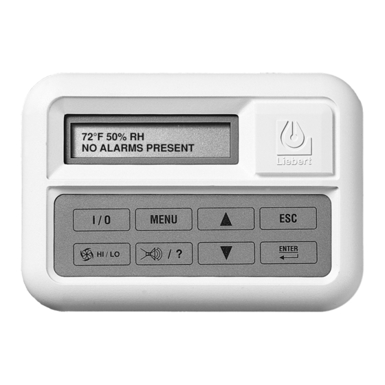
A range of sizes and configurations is available to meet varying sites’ needs. The Liebert Mini-Mate2 is also easy to use. Advanced microprocessor technology allows easy, precise control, and menu-driven monitoring keeps you informed of system operation through the LCD readout. -
Page 15: Standard Features -2 & 3 Ton Systems
Outdoor Prop Fan Condensing Units include scroll compressor, condenser coil, R-407C unit charge, prop fan, liquid-line solenoid valve, high pressure switch, Liebert Lee-Temp head pressure control and hot gas bypass. Condensing unit is designed for outdoor locations with operating ambients ranging from -30°F to 95°F (-34°C to 35°C). -
Page 16: System Controls
Other Standard Control Features • Adjustable auto restart • Calibrate sensors • 5 day/2 day setback • Predictive humidity control • Password protection • Common alarm output • Alarm enable/disable • Remote shutdown terminals • Self-diagnostics ® ™ Liebert Mini-Mate2... -
Page 17: Optional Factory-Installed Features-Evaporator/Chilled Water Units
Remote Humidifier Contact allows the unit’s humidity controller to control a humidifier outside the unit. Power to operate the remote humidifier does not come from the Liebert Mini-Mate2. Available on units with or without internal humidifier. -
Page 18: Free-Cooling
Free-cooling option: A second cooling coil allows the system to take advantage of colder outdoor temperatures and bypass compressor operation. Liebert Mini-Mate2 When the water temperature goes below 45°F (7°C), cooling switches over to free-cooling operation. A separate chilled water source can Free - also be used with air-cooled systems. -
Page 19: Ship -Loose Accessories -Field -Installed
Available in 15-foot (4.5m) and 30-foot (9m) sections. The Refrigerant-Line Sweat Adapter Kit contains two suction and two liquid line fittings that allow field-supplied refrigerant piping between the evaporator and condensing unit. ® ™ Liebert Mini-Mate2... -
Page 20: Remote Monitoring, Autochangeover And Leak Detection Equipment
The Liebert AC4 Autochangeover Controller provides autochangeover and autosequence control for up to four Liebert Mini-Mate2 units within a room. The Liebert AC4 will enable redundant units in an alarm condition, balance usage and test standby units at programmed intervals. Two common alarm relay outputs are available. -
Page 21: Site Preparation And Installation
Table 5 Application limits, indoor water/glycol-cooled condensing units Input Voltage Entering Fluid Temperature Minimum Maximum Minimum Maximum +10% 65°F (18.3°C) * 115°F (46°C) Operation below 65°F (18°C) may result in reduced valve life and fluid noise. ® ™ Liebert Mini-Mate2... -
Page 22: Room Preparation
This could result in crossing air patterns, uneven loads and competing operating modes. When installing an air-cooled or water/glycol-cooled unit inside a space, ensure that national and local codes are met for refrigerant concentration limits that might vary with building type and use. ® ™ Liebert Mini-Mate2... -
Page 23: Figure 8 Air-Cooled Systems, 2 And 3 Tons
Split System Evaporator Supply and Return Air Plenum Supply and Return Air Ducted Remote Water/Glycol Condensing Unit Remote Water/Glycol Condensing Unit Figure 10 Chilled water systems, 3 tons Chilled Water Ducted Chilled Water Supply and Return Plenum ® ™ Liebert Mini-Mate2... -
Page 24: Ceiling Unit Weights
If you discover any damage when you uncrate the unit, report it to the shipper immediately. If you later find any concealed damaged, report it to the shipper and to your Liebert supplier. Packaging Material All material used to package this unit is recyclable. -
Page 25: Close-Coupled Installations
The optional filter box is available for the unit and mounts directly to the return air opening of the evaporator. The 2 and 3 ton filter box is supplied with a MERV 8 filter (per ASHRAE 52.2-2007) measuring 20 in. x 20 in. x 4 in. (508x508x102mm). ® ™ Liebert Mini-Mate2... -
Page 26: Piping Connections And Coolant Requirements
The drain line must be located so it will not be exposed to freezing temperatures. The drain should be the full size of the drain connection. The evaporator drain pan includes a float switch to prevent operation if drain becomes blocked. ® ™ Liebert Mini-Mate2... - Page 27 Chilled water supply and return lines must be insulated. Insulating them will prevent condensation of the water supply and return lines to the unit. The minimum recommended water temperature is 42¡F. Design pressure is 300psig (2068 kPag). Connection sizes are 7/8 in (22.2mm) OD copper for 3 ton units. ® ™ Liebert Mini-Mate2...
- Page 28 Risk of frozen pipes and corrosion from improper coolant mixture. Can cause equipment and building damage. When piping or the Liebert Mini-Mate2 may be exposed to freezing temperatures, charge the system with the proper percentage of glycol and water for the coldest design ambient.
-
Page 29: Figure 12 Refrigerant Piping Diagram
A brazing alloy with a minimum temperature of 1350°F (732°C), such as Sil-Fos. Avoid soft solders such as 50/50 or 95/5. 1. Use sweat adapter kit matched to the Liebert Mini-Mate2 and outdoor condensing unit refrigerant connection sizes. 2. Measure pipe runs and calculate pipe size and equivalent feet of suction and liquid lines per Tables 8 and 12. -
Page 30: Table 8 Recommended Refrigerant Line Sizes
1.0 (0.4) 1-1/8 — 1.7 (0.7) 1-3/8 — 2.7 (1.1) Table 11 Refrigerant charge in Liebert pre-charged R-407C line sets Line Size, in. Length, ft. (m) Charge R-407C, oz (kg) 15 (4.5) 5 (0.14) 3/8 liquid 30 (9) 10 (0.28) 15 (4.5) -
Page 31: Table 13 Refrigerant Charge
This final quarter-turn is necessary to insure that the joint will not leak. Refer to Table 14 for torque requirements. Table 14 Connection sizes and torque Size OD Cu Model Tons Coupling Size Torque Ib-ft. 2 and 3 10-12 2 and 3 35-45 ® ™ Liebert Mini-Mate2... -
Page 32: Figure 13 Dimensions, Evaporator And Chilled Water Units With Direct Drive Blower
Net weights—evaporator and chilled water units Model # 60Hz 50Hz Weight, lb (kg) MM*24E — 225 (102) MM*24K — 245 (111) MM*36E MM*35E 225 (102) MM*36K MM*35K 245 (111) MM*40C MM*39C 230 (104) Source: DPN000193, Rev. 3 ® ™ Liebert Mini-Mate2... -
Page 33: Figure 14 Dimensions, Evaporator Units With Optional Belt Drive Blower Assembly
14" Dimension (356mm) Outlet Dimension 18 " (457mm) Outlet Dimension DPN000194 Rev. 3 Table 16 Net weight, high static blower module Net Weight Unit lb (kg) High Static 85 (39) Blower Module Source: DPN000194, Rev. 3 ® ™ Liebert Mini-Mate2... -
Page 34: Figure 15 Evaporator And Chilled Water Unit Piping Data
On Unit with Air Distribution Plenum CONDENSATE PUMP (Field-installed) Note: On Unit with Air Outlet Ductwork 3/4" (19.1mm) Flexible Rubber Tubing Assembly DPN00192 (Supplied with Pump Kit) must be installed on pump Rev. 1 end of rigid piping; support as required. ® ™ Liebert Mini-Mate2... -
Page 35: Condensate Pump Kit Installation-All Units
• Control wiring between the evaporator unit and the condensing unit, if applicable. • Control wiring between the control panel (wall box) and the evaporator unit control board. Entrance locations for these connections are noted on drawing in each installation section. ® ™ Liebert Mini-Mate2... - Page 36 The circuit breaker, contained in the transformer housing, is sized only for the factory-supplied control system. Additional control wiring will be required if your system includes other optional monitoring and control devices. NOTE Refer to specifications for full load amp. and wire size amp. ratings. ® ™ Liebert Mini-Mate2...
-
Page 37: Figure 16 Evaporator And Chilled Water Unit Electrical Connections
Site monitoring connection. Terminals TB4-1(+) TB4-2(-) are for connection of a 2 wire. twisted pair, communication cable (available from Emerson or others) to optional Liebert SiteScan Customer remote alarm connection field-supplied 24V. Class 2 wiring to conn TB1-1, TB1-2 & TB1-3 Remote unit shutdown. -
Page 38: Indoor Air-Cooled Centrifugal Fan Condensing Unit Installation
Electrical Connections Refer to 5.5.5 - Electrical Connections for general wiring requirement and cautions. Refer to the unit’s electrical schematic when making connections. Refer to the unit’s specifications for full load amp and wire size amp ratings. ® ™ Liebert Mini-Mate2... -
Page 39: Piping Connections
Table 17 Indoor condensing unit airflow, CFM at 0.5 iwg esp 2 Ton 3 Ton 1000 1430 ® ™ Liebert Mini-Mate2... -
Page 40: Figure 18 Indoor Air-Cooled Centrifugal Condenser Dimensions And Pipe Connections
Male Quick Connect DPN000206 Rev. 1 Table 18 Centrifugal condenser dimensions, weights Net Weight Model lb (kg) MC*24A 230 (104) MC*35A 1-7/16 (37) 11-7/16 (290) 1/2 (13) 20-7/16 (519) 240 (109) MC*36A Source: DPN000206, Rev. 1 ® ™ Liebert Mini-Mate2... -
Page 41: Figure 19 Centrifugal Condenser Electrical Connections
Line voltage electric power Factory-wired supply conduit entrance to components on electric panel Single- or three-phase electric service not by Liebert Connection terminal for field-supplied earth grounding wire Low voltage electric power supply entrance Heat rejection connection Field-supplied 24V NEC Class 2 wiring. -
Page 42: Outdoor Air Cooled Condensing Unit Installation
24" (610mm) for component access and removal. Shaded area Removable panel for access indicates a minimum to high-voltage and low-voltage clearance of 18" (457mm) connections and refrigeration DPN000130 for proper air flow components Rev. 1 ® ™ Liebert Mini-Mate2... -
Page 43: Piping Connections
Field-supplied control wires must be connected between the evaporator and the condensing unit. (See Figure 16 and the electrical schematic on the units for more details.) Four wires are required between the evaporator and condensing unit. ® ™ Liebert Mini-Mate2... -
Page 44: Water And Glycol Cooled Condensing Unit
Pressure Balancing Limiting Connect Coupling Valve Switch Liquid Line Female Quick Connect Coupling * Use Liebert sweat adapter kit with field Field Piping hard piping or use Liebert pre-charged Expansion Valve line set. Close-coupling option Factory Piping available with MCD. -
Page 45: Figure 22 Cabinet Dimensions And Piping Data, Water/Glycol Indoor Condensing Module
PIPING CONNECTIONS DPN000208 for Low Voltage Rev. 4 Connection Table 20 Net weight, indoor water/glycol-cooled condensing unit Model # Weight 60Hz 50Hz lb (kg) MC*26W — 175 (79) MC*38W MC*37W 220 (100) Source: DPN000208, Rev. 4 ® ™ Liebert Mini-Mate2... -
Page 46: Electrical Connections
Water/Glycol cooled units include a coolant flow regulating valve which is factory adjusted and should not need field adjustment. Standard pressure and high pressure valves are adjusted differently. Contact Emerson Network Power Liebert Services before making any adjustments. ® ® ™... -
Page 47: Figure 23 General Arrangement, Water/Glycol Split Systems
Coupling Female Quick Connect Expansion Coupling Valve Fluid Return * Use Liebert sweat adapter kit with field From Unit hard piping or use Liebert pre-charged line set. Close-coupling option available with MCD. 3 - Way Water Fluid Supply Evaporator Coil... -
Page 48: Optional Equipment Piping
To Unit FIELD PIPING NOTE: RECOMMENDED PIPING FOR UNITS WITH FREE-COOLING COIL OPTION FACTORY PIPING AND WATER/GLYCOL CONDENSER. * Components are not supplied by Emerson DPN000219 but are recommended for proper circuit Rev. 3 operation and maintenance. ® ™ Liebert Mini-Mate2... -
Page 49: Hot Water Reheat Coil
Valves * FIELD PIPING Hose FACTORY PIPING Bibs * NOTE: Hot water reheat only available on chilled water units. * Components are not supplied by Liebert but are recommended DPN000197 for proper circuit operation and Rev. 2 maintenance. ® ™ Liebert... -
Page 50: Checklist For Completed Installation
___ 20. Inspect all piping connections for leaks during initial operations. Correct as needed. ___ 21. Drain pan is installed under ducted cooling unit and ceiling mounted condensing unit. ___ 22. Rubber band is removed from evaporator condensate pan float switch. ® ™ Liebert Mini-Mate2... -
Page 51: Microprocessor Control
ICROPROCESSOR ONTROL The Microprocessor Control for the Liebert Mini-Mate2 features an easy to-use, menu-driven liquid crystal display. The menus, control features and circuit board details are described in this section. Detailed information concerning controls (7.0 - System Performance Microprocessor Controls) and alarms (8.0 - Alarms) are provided. -
Page 52: Main Menu
40-90°F (5-32°C) Temperature Sensitivity 2.0°F 1-9.9°F (0.6-5.6°C) Humidity Setpoint 20-80% RH Humidity Sensitivity 1-30% RH High Temperature Alarm 80°F 35-95°F (2-35°C) Low Temperature Alarm 65°F 35-95°F (2-35°C) High Humidity Alarm 15-85% RH Low Humidity Alarm 15-84% RH ® ™ Liebert Mini-Mate2... -
Page 53: Status
Table 22 can be used to devise a setback plan. Table 22 Microprocessor night and weekend setback Event Weekend Weekday Time 1 Temperature 1 Sensitivity 1 Humidity 1 Humidity Sensitivity 1 Time 2 Temperature 2 Sensitivity 2 Humidity 2 Humidity Sensitivity 2 ® ™ Liebert Mini-Mate2... -
Page 54: Setup Operation
(If unauthorized changes are being made, the passwords may be compromised and new ones should be selected). The password function can be disabled by setting DIP switch 8 in the wall box to ON, then resetting power to the unit. ® ™ Liebert Mini-Mate2... -
Page 55: Calibrate Sensors
DISABLED, the alarm has no effect on the common alarm relay. Use the Up/Down arrows to scroll to a particular alarm, press the Enter button to select it, then press the Enter button again to select Yes or No. ® ™ Liebert Mini-Mate2... -
Page 56: Custom Alarms
TB1. These switches are factory-set and should not require any user changes. The setting and function of the switches can be individually read on the LCD. NOTE In order to update the DIP switch settings, power must be cycled Off, then On, from the unit disconnect switch. ® ™ Liebert Mini-Mate2... -
Page 57: Table 25 Switch Settings (Wall Box Board)
Not Used--Must remain in OFF position Not Used--Must remain in OFF position Not Used--Must remain in OFF position Not Used--Must remain in OFF position Compressor on continuously Economy Mode for tight control Disable Setback Enable Setback Enable Password Disable Password ® ™ Liebert Mini-Mate2... -
Page 58: Run Diagnostics (Available On Rev 1.001.0 And Higher)
Test Control Board By selecting this function, the microcontroller will perform a self test lasting approximately 10 seconds. When the test is complete, the display will show the ROM checksum, ROM part number and firmware vision number. ® ™ Liebert Mini-Mate2... -
Page 59: Figure 27 Control Menu
Wkdy Hsens 2 Setup Operation Custom Text Restart TD Custom Text 1 C/F Degrees Custom Text 2 Humidity Control Dipswch 00000000 12345678 Diagnostics Test Inputs Setpoint Password Test Outputs Enter New PSW Test Microcontroller Setpt PSW = 000 ® ™ Liebert Mini-Mate2... -
Page 60: Figure 28 Control Board (Inside Evaporator)
Connection to TB3 Pin 1 of wall box TB1-6 Common Alarm Connection TB4-2 Site Monitoring Connection (-) TB1-5 Remote Shutdown TB4-1 Site Monitoring Connection (+) TB1-4 Remote Shutdown Remote Sensor Connection Figure 29 Wall box board Wall Box DIP switches 1-8 ® ™ Liebert Mini-Mate2... -
Page 61: System Performance Microprocessor Controls
System Performance Microprocessor Controls YSTEM ERFORMANCE ICROPROCESSOR ONTROLS This section provides a detailed description of how the Liebert Mini-Mate2 responds to operator inputs and room conditions. Temperature Control 7.1.1 Cooling/Heating Required The temperature control program for the microprocessor is based on a calculated percentage requirement for cooling/heating. -
Page 62: Heating Operation
Ground Current Detector (GCD) A Ground Current Detector is factory-installed on all 1-ton through 3-ton Liebert Mini-Mate2 units with reheat. The GCD detects reheat leakage current and shuts down operation of the reheat. A steady green LED indicates that the reheat is operating properly. A red LED indicates that the reheat has failed and both the reheat element and GCD need to be replaced. -
Page 63: Humidity Control
7.3.1 Communication The control system uses a two-wire, RS-422 channel to communicate with Liebert Site Products via a proprietary protocol. A converter board (ECA2) is available to allow communications with a “dumb” terminal or a computer using RS-232 channel. More details are provided in the Site Products and ECA2 user manual. -
Page 64: Alarms
The following list provides a definition and troubleshooting suggestions for each type of alarm. Refer to 11.0 - Troubleshooting for additional details. If you need further assistance, contact your Liebert supplier. THE CUSTOMER MUST SPECIFY ALARM(S) AT THE TIME OF ORDER. OTHER DEVICES AND WIRING MAY BE REQUIRED AT THE FACTORY FOR SOME OF THE ALARMS. -
Page 65: Humidity Level
The Loss of Power Alarm will activate (after power is restored to the unit) if the unit has lost power or the disconnect switch was incorrectly turned off before the unit On/Off switch was pressed. A Liebert remote monitoring unit (optional) will immediately indicate loss of power. -
Page 66: Short Cycle
This smoke detector is not intended to function as or replace any room smoke detection system that may be required by local or national codes. Locate source of smoke and follow appropriate emergency procedures. ® ™ Liebert Mini-Mate2... -
Page 67: System Testing And Maintenance
A connection point is provided for remote shutdown devices supplied by the customer. This terminal strip is located on the printed circuit board. (Terminals TB1-4 and TB1-5 are fitted with a jumper when no remote shutdown device is installed). ® ™ Liebert Mini-Mate2... -
Page 68: Maintenance
Air Distribution Since all unit models are designed for constant volume air delivery, any unusual restrictions within the air circuit must be avoided. Note that high efficiency filters can reduce air performance and evaporator capacity. ® ™ Liebert Mini-Mate2... -
Page 69: High Static Belt Drive Blower Package (Option)
Conversely, if too much refrigerant is being supplied, then the superheat will be low. The correct superheat setting is between 10 and 15°F (5.6 and 8.3°C). ® ™ Liebert Mini-Mate2... - Page 70 The water regulating valve is designed to begin opening at 180 psi (1240kPa) and be fully opened at 240 psi (1655kPa). The valve is factory-set and should not need adjustment. There is significant difference in the way standard pressure and high pressure valves are adjusted. Consult Liebert Services.
-
Page 71: Figure 31 Hot Gas Bypass
7. There may be a fluctuation of approximately 3 to 6 PSIG (21 to 41kPa) on the evaporator due to the differential on the hot gas bypass. 8. Return temperature setpoint to the desired setting. Figure 31 Hot gas bypass ® ™ Liebert Mini-Mate2... -
Page 72: Humidifier Circuit Board Adjustments
The humidifier control board governs humidifier operation. There are three potentiometers mounted on the board and can be used to adjust for extreme water conductivity conditions. ® ™ Liebert Mini-Mate2... -
Page 73: Replacement Procedures
If adjustment is necessary and a change of 3 to 4 percent in either direction does not permit normal operation of the unit, consult your Liebert supplier. The POT1 controls the duration of the drain cycle. This adjustment is factory-set at 60 seconds and should not be readjusted without consulting your Liebert supplier. -
Page 74: Electrical Failure
9. Charge the system with refrigerant (R-407C) based on requirements of the evaporator, condensing unit and lines. Refer to the unit nameplate. 10. Apply power and operate the system. Check for proper operation. Refer to Table 29. ® ™ Liebert Mini-Mate2... -
Page 75: Replacing The Humidifier Canister
• When replacing the wiring, connect the red wire from terminal #1 on the interface to the red tip terminal on the canister. Reconnect the power wires as before (#2 on the left and #1 on the right). • When replacing the canister, always check the fill and drain solenoids for proper operation. ® ™ Liebert Mini-Mate2... -
Page 76: Maintenance Inspection Checklist
___ 4. pH level ___ 3. Bearings in good condition. Electric Panel ___ 4. Refrigerant lines properly ___ 1. Check electrical connections. supported. ___ 2. Operational sequence Notes:_______________________________________________________________________________________ Signature: Make photocopies of this form for your records ® ™ Liebert Mini-Mate2... -
Page 77: Troubleshooting
(including filter screen) and check nylon overflow line if canister is full. Canister fill rate is not Check fill valve screen opening and capillary tube for obstructions. keeping up with the Check water supply pressure (minimum 10 PSIG). steam output. ® ™ Liebert Mini-Mate2... - Page 78 NOTE: It may take up to 20 seconds for the display to appear on the wall box LCD after power is applied. ® ™ Liebert Mini-Mate2...
- Page 80 +39 049 9719 111 Fax: +39 049 5841 257 While every precaution has been taken to ensure the accuracy and completeness of this literature, Liebert Corporation assumes no Asia responsibility and disclaims all liability for damages resulting from use of 29/F, The Orient Square Building this information or for any errors or omissions.