Table of Contents
Advertisement
Advertisement
Table of Contents

Related Manuals for LG L1920P


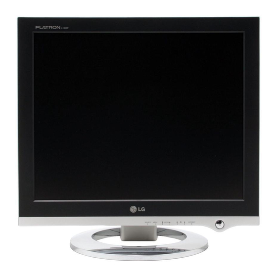
Summary of Contents for LG L1920P
- Page 1 User’s Guide L1920P ake sure to read the Important Precautions before using the product. Keep the User's Guide(CD) in an accessible place for furture reference. ee the label attached on the product and quote this information to your dealer when you require service.
-
Page 2: Important Precautions
Important Precautions This unit has been engineered and manufactured to ensure your personal safety, however improper use may result in potential eletrical shock or fire hazards. In order to allow the proper operation of all safeguards incorporated in this display, observe the following basic rules for its installation, use, and servicing. - Page 3 Important Precautions On Installation Do not allow anything to rest upon or roll over the power cord, and do not place the display where the power cord is subject to damage. Do not use this display near water such as near a bathtub, washbowl, kitchen sink, laundry tub, in a wet basement, or near a swimming pool.
-
Page 4: Connecting The Display
Connecting the Display Using the Computer Connect the signal input cable and the power cord. (see next page) Separate the back cap by sliding its lower section downward as shown in the picture. After the cables are connected, set the back cap into the groove of the upper section and reassemble by pushing upward. - Page 5 Connecting the Display Using the Computer Connect the signal cable. When attached, tighten the thumbscrews to secure the connection. Connect the power cord into a proper power outlet that is easily accessible and close to the display. NOTE This is a simplified representation of the rear view. This rear view represents a general model;...
-
Page 6: Control Panel Functions
Control Panel Functions Front Panel Controls Control Power Button Power Indicator AUTO/SELECT Button Buttons MENU Button Function Use this button to turn the display on or off. This Indicator lights up blue when the display operates normally(On Mode). If the display is in Sleep Mode (Energy Saving), this indicator color changes to amber. - Page 7 Control Panel Functions Control P I C T U R E M E N U To select DSUB ANALOG, DVI DIGITAL as the active input. This feature is used when two computers are connected to the display. The display automatically detects the proper input when only one video source is connected.
-
Page 8: On Screen Display (Osd) Control Adjustment
On Screen Display (OSD) Control Adjustment Screen Adjustment Making adjustments to the image size, position and operating parameters of the display is quick and easy with the On Screen Display Control system. A short example is given below to familiarize you with the use of the controls. The following section is an outline of the available adjustments and selections you can make using the OSD. - Page 9 On Screen Display(OSD) Selection and Adjustment The following table indicates all the On Screen Display control, adjustment, and setting menus. Main menu PICTURE BRIGHTNESS CONTRAST GAMMA COLOR PRESET 6500K GREEN BLUE HORIZONTAL POSITION VERTICAL CLOCK TRACKING PHASE LANGUAGE SETUP POSITION WHITE BALANCE POWER INDICATOR FACTORY RESET...
-
Page 10: On Screen Display(Osd) Selection And Adjustment
On Screen Display(OSD) Selection and Adjustment You were introduced to the procedure of selecting and adjusting an item using the OSD system. Listed below are the icons, icon names, and icon descriptions of the all items shown on the Menu. NOTE OSD (On Screen Display) menu languages on the monitor may differ from the manual. -
Page 11: To Improve The Clarity And Stability Of The Screen
On Screen Display(OSD) Selection and Adjustment To improve the clarity and stability of the screen OSD Adjust T R A C K I N G To customize the screen status for a user's operating environment OSD Adjust S E T U P S E T U P If this does not improve the screen image, restore the factory default settings. -
Page 12: Troubleshooting
Troubleshooting Check the following before calling for service. No image appears No image appears Is the power cord of the display connected? Is the power indicator light on? Is the power on and the power indicator blue or green? Is the power indicator amber? Do you see an "OUT OF RANGE"... -
Page 13: Display Image Is Incorrect
Troubleshooting Display image is incorrect Display Position is incorrect. On the screen background, vertical bars or stripes are visible. Any horizontal noise appearing in any image or characters are not clearly portrayed. The screen color is mono or abnormal. The screen blinks. Press the AUTO/SELECT button to automatically adjust your display image to the ideal setting. -
Page 14: Have You Installed The Display Driver
Troubleshooting Have you installed the display driver? Have you installed the display driver? Do you see an "Unrecognized monitor, Plug&Play (VESA DDC) monitor found" message? USB function USB function cannot be setup. Be sure to install the display driver from the display driver CD (or diskette) that comes with your display. -
Page 15: Specifications
Specifications Display 19 inches (48.18cm) Flat Panel Active matrix-TFT LCD Anti-Glare coating 19 inches viewable 0.294 mm pixel pitch Horizontal Freq. Sync Input Vertical Freq. Input Form Signal Input Video Input Input Form Resolution Recommend DDC 2B Plug&Play On Mode Power Sleep Mode Consumption... -
Page 16: Preset Modes (Resolution)
Specifications Preset Modes (Resolution) Display Modes (Resolution) 640 x 350 720 x 400 640 x 480 VESA 640 x 480 VESA 800 x 600 VESA 800 x 600 832 x 624 VESA 1024 x 768 VESA 1024 x 768 1152 x 870 VESA 1152 x 900 VESA... -
Page 17: Signal Connector Pin Assignment
Specifications Signal Connector Pin Assignment DVI-D Connector Signal(DVI-D) T. M. D. S. Data2- T. M. D. S. Data2+ T. M. D. S. Data2/4 Shield T. M. D. S. Data4- T. M. D. S. Data4+ DDC Clock DDC Data Analog Vertical Sync. T. - Page 18 How to Install the VESA Standard wall mounting This monitor meets VESA-compliant mounting interface pad specifications. Please the monitor on a piece of cloth or other soft surface with the front side facing downward and remove the rear cap. Install the VESA standrad wall mounting. Slide off the lower section of the cover base with two hands as shown in the picture.
-
Page 19: Usb Connection
Making use of USB (Universal Serial Bus) - Optional USB (Universal Serial Bus) is an innovation in connecting your different desktop peripherals conveniently to your computer. By using the USB, you will be able to connect your mouse, keyboard, and other peripherals to your display instead of having to connect them to your computer. -
Page 20: Usb Specifications
Making use of USB (Universal Serial Bus) - Optional USB Specifications USB standard Downstream power supply Communication speed USB port IMPORTANT: These USB connectors are not designed for use with high-power USB devices such as a video camera, scanner, etc. LGE recommends connecting high-power USB devices directly to the computer Rev. - Page 21 Digitally yours...