Table of Contents
Advertisement
Quick Links
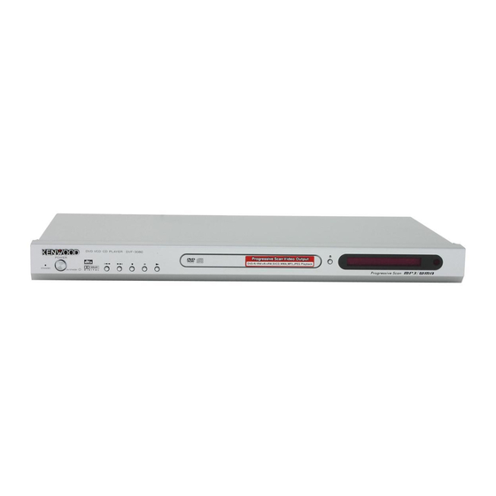
DVD/VCD/CD PLAYER
DVF-3080-S/8100
SERVICE MANUAL
POWRE
Jack, RCA *
(E63-)
COAXIAL
R
DIGITAL OUT
(PCM/BIT STREAM)
Y
OUT
COMPONENT VIDEO
S VIDEO
In compliance with Federal Regulations, following are repro-
duction of labels on, or inside the product relating to laser
product safety.
Caution : No connection of ground line if disassemble
the unit. Please connect the ground line on
rear panel, PCBs, Chassis and some others.
Panel *
(A60-)
Tray panel *
(A29)
L
OUT
OUT
AUDIO
VIDEO
C
C
B
R
OUT
© 2004-7 PRINTED IN KOREA
B51-5894-00 (K/K) PDF
* Refer to parts list on page 31.
KENWOOD Corp. certifies this equipment conforms to DHHS
Regulations No.21 CFR 1040. 10, Chapter 1, subchapter J.
DANGER : Laser radiation when open and interlock defeated.
AVOID DIRECT EXPOSURE TO BEAM.
Front glass
(B03-3945-08)
Case
(A01-3925-08)
Power cord *
(E30-)
70%
70%
Advertisement
Table of Contents

Related Manuals for Kenwood DVF-3080-S


Summary of Contents for Kenwood DVF-3080-S
- Page 1 * Refer to parts list on page 31. In compliance with Federal Regulations, following are repro- KENWOOD Corp. certifies this equipment conforms to DHHS duction of labels on, or inside the product relating to laser Regulations No.21 CFR 1040. 10, Chapter 1, subchapter J.
-
Page 2: Table Of Contents
DVF-3080-S/8100 CONTENTS / ACCESSORIES / CAUTIONS CONTENTS CONTENTS / ACCESSORIES / CAUTIONS....2 PC BOARD ..............19 DISASSEMBLY FOR REPAIR........3 CIRCUIT VOLTAGE CHART ........21 BLOCK DIAGRAM ............4 SCHEMATIC DIAGRAM ..........23 DECK MECHANISM ............7 EXPLODED VIEW .............30 ELECTRICAL TROUBLESHOOTING GUIDE ...11 PARTS LIST...............31 WAVEFORMS............15... -
Page 3: Disassembly For Repair
DVF-3080-S/8100 DISASSEMBLY FOR REPAIR 1) Insert and push a Driver in the emergency eject hole(A) at the right side, or put the Driver on the Lever(B) of the Gear Emergency and pull the Lever(B) in direction of arrow so that the Tray Disc is ejected about 15~20mm. - Page 4 DISC VD33D VD33D VD33D IC502 DAC_RST IC503 KV802..DMUTE D2_T[1:3] CN505 KV852..IC506 16BIT SCART_16:9 EJTAG 74LCX373 RGB_SEL 4Bank 8BIT SDRAM SPINDLE FLASH ROM DVD : A,B,C,D,RF0 PICK MOTOR CD : A,B,C,D,E,F,RF0 CDMDI,DVDMDI MA[00:11] TRST CDLD,DVDLD,SVREF21 DMCLK SLED LOADING (FEEDING) MOTOR MOTOR CASJ...
-
Page 5: Block Diagram
DVF-3080-S/8100 BLOCK DIAGRAM 2. Power(SMPS) Block Diagram RECTIFIER(FLD) -23VA RECTIFIER(14V) 1.8V MULTI REG. RECTIFIER(3.8V) 3.3V RECTIFIER(10V) 5.2VA RECTIFIER(5.2V) FEED B. PWR CTL 3. SERVO Block Diagram ROMDATA[0:7] DVDLD,CDLD,CD_DVD ROMAD[0:21] IC501 DVDMDI.CDMDI FLASH ROMRD ROMWR ALI M3355 SVREF21 PICK DVDPLAYER IIC/VFD/DAC_SCK... - Page 6 DVF-3080-S/8100 BLOCK DIAGRAM 4. MPEG & MEMORY Block Diagram IC503 SDRAM IC504 EEPROM TV_DAC0 DVD-MD1 , CD-MDI TV_DAC1 VIDEO TV_DAC2 SVREF21, DVDLD CDLD, Interface TV_DAC3 IC501(MPEG+DSP+RF) DVD:A,B,C,D,RFO BCLK,LRCLK,DACCLK ALiM3355 CD:A,B,C,D,E ,F ,RFO DAC_RST AUDIO SER(0:3) F+, F-, T+, T-, CD_DVD...
- Page 7 DVF-3080-S/8100 DECK MECHANISM PARTS LOCATION • Top View (With Tray) Procedure Disass Fig- Parts Fixing Type embly Starting No. Main Base Clamp Assembly Disc 1, 2 Plate Clamp 1, 2, 3 Magnet Clamp 1, 2, 3, 4 Clamp Upper Tray Disc...
-
Page 8: Deck Mechanism
DVF-3080-S/8100 DECK MECHANISM DISASSEMBLY Fig. 4-1 Fig. 4-2 1. Main Base (Fig. 4-1) 2. Tray Disc (Fig. 4-2) 1-1. Clamp Assembly Disc 1) Insert and push a Driver in the emergency eject hole(A) at the right side, or put the Driver on the 1) Place the Clamp Assembly Disc as Fig. - Page 9 DVF-3080-S/8100 DECK MECHANISM DISASSEMBLY Fig. 4-3 3. Base Assembly Sled (Fig. 4-3) 3-3. Gear Rack 1) Release the Scerw(S3) 1) Release 4 Screw(S2). 2) Disconnect the FFC Connector(C1) 4. Rubber Rear (Fig. 4-3) 3-1. Gear Feed 3-2. Gear Middle...
- Page 10 DVF-3080-S/8100 DECK MECHANISM DISASSEMBLY Fig. 4-4 5. Frame Assembly Up/Down (Fig. 4-4) 8. Gear Loading (Fig. 4-4) 9. Guide Up/Down (Fig. 4-4) Note 1) Move the Guide Up/Down in direction of arrow(A) as Put the Base Main face down(Bottom Side) Fig.(A)
- Page 11 1. Power check flow 2. System operation flow No VF+ No 5V_A Power on 1.initializes SERVO,DSP and RISC registers Is 5.2VA section working? Is 5.2VA section working? 2.write RISC code to SDRAM 3.Reset RISC Is 5.2V present at emitter Check F102 No 5.2VA Show LOGO of Q107?
- Page 12 Test Reset or Power on Check the AC Voltage Check the Power PART (110V or 220V) Flash Check connection on lines between FLASH Show LOGO Memory operates & M3355 and the FLASH access time whether is suitable or not. Properly? Switch on the Power PCBA Check connection lines between SDRAM...
- Page 13 Check the laser power circuit Does Laser turns on when LD01 or LD02 output on M3355 and connecting to reading disc?) the SLED move Motor properly? power transistor. (Q201, Q202) Check the connection line of to inner side when it is at Driver DRVSB DRVSB signal outer position...
- Page 14 Proper Check connections between Normal Check connection between M3355 Focus ON OK? signals on A, B, C, Audio output DAC received M3355 and pick-up head. & Audio DAC. (Check DAC_RST#, D of M3355 when disc playback? correct data SER3, BCLK, LRCK,MCLK stream? Check the related circuit .
-
Page 15: Waveforms
DVF-3080-S/8100 WAVEFORMS 1. SYSTEM 27MHz CLOCK, RESET SIGNAL 1) M3355 main clock is at 27MHz(X501) 2) M3355 reset is low active 5.2VA PWR_CTL(CN505 PIN7) 3.1V,27MHz M_RESET(CN505 PIN9) TRST FIG 1-1 FIG 1-2 3. TRAY OPEN/CLOSE SIGNAL 2. SDRAM CLOCK 1) Tray open/close waveform 1) SDRAM clock is at 135MHz CLK=135MHz,Vp-p=3.3V... -
Page 16: Disc Type Judgement Waveform
DVF-3080-S/8100 WAVEFORMS 6. LASER POWER CONTROL RELATED 7. DISC TYPE JUDGEMENT WAVEFORM SIGNAL(NO DISC CONDITION) F+(CN201 PIN15) (CN201 PIN22) DVDMDI(0V/180mV) FE(IC501 PIN27) DVDLD(3.2V/2.2V) (IC501 PIN39) CDLD(3.2V/2.3V) SBAD(IC501 PIN14) (IC501 PIN40) FIG 7-1(DVD) FIG 6-1 F+(CN201 PIN15) F+(CN201 PIN15) FE(IC501 PIN27) - Page 17 DVF-3080-S/8100 WAVEFORMS 10. TRACKING CONTROL RELATED SIGNAL(System checking) TE(IC501 PIN28) TE(IC501 PIN28) TRACK(IC501 PIN77) TRACK(IC501 PIN77) T+(CN201 PIN16) T+(CN201 PIN16) T-(CN201 PIN17) T-(CN201 PIN17) FIG 10-2(CD) FIG 10-1 (DVD) 11. RF WAVEFORM 12. M3355 AUDIO OPTICAL AND COAXIAL OUTPUT(ASPDIF) IECDAOUT...
- Page 18 DVF-3080-S/8100 WAVEFORMS 2) Audio Related Signal SER3(IC501 PIN167) BCLK(IC501 PIN170) 2.312MHz LRCLK(IC501 PIN168) 48KHz FIG 14-2...
-
Page 20: Pc Board
PC BOARD 2. KEY P.C.BOARD (Solder Side) 3. FRONT P.C.BOARD (Solder Side) 4. SMPS P.C.BOARD Note: This manual has no Scart pcb. Refer to the schematic diagram for the value of resistors and capacitors. - Page 21 MODE MODE MODE MODE MODE STOP PLAY HOLD STOP PLAY HOLD STOP PLAY HOLD STOP PLAY HOLD STOP PLAY HOLD PIN NO. PIN NO. PIN NO. PIN NO. PIN NO. IC201 (IP4504) I C 5 0 1 ( M 3 3 5 5 ) XDPD_D 2.11 XROMADR[17]...
- Page 22 MODE MODE MODE MODE MODE MODE MODE MODE MODE STOP PLAY HOLD STOP PLAY HOLD STOP PLAY HOLD STOP PLAY HOLD STOP PLAY HOLD STOP PLAY STOP PLAY STOP PLAY STOP PLAY PIN NO. PIN NO. PIN NO. PIN NO. PIN NO.
-
Page 23: Parts List
1. POWER(SMPS) CIRCUIT DIAGRAM VF(+) Power dead Please replace a defective power supply unit with a new one except fuse. R102 is defective VF(-) Power dead ZD102 is defective 3.3V, 1.8V, 8V, 12V Power dead IC105 is defective Power dead IC101 is defective 5V Power dead Q107 is defective... - Page 24 VIDEO OPTION C624, R651, R661, R666, DESTINATION IC501 DAC0 DAC1 DAC2 DAC3 DAC4 DAC5 660,662 663,664 M3355G CVBS Cb/B Cr/R K,P,X,Y M3355A CVBS Cb/B Cr/R YC-Y YC-C 0-OHM M3355G (M3355A) CVBS (TV_DAC0) (NC) (TV_DAC1) (820) Cb/B (TV_DAC2) (820) Cr/R All Video signal isn't (TV_DAC3) appear or bad (820)
- Page 25 DVF-3080-S/8100 3. SYSTEM CIRCUIT DIAGRAM Video signal not appeared CAUTION: For continued safety, replace safety critical components only with manufacturer's recom- mended parts (refer to parts list). indicates safety critical components. R526 For continued protection against risk of fire, replace only with same type KTC3875S-GR-T1 and rating fuse(s).
- Page 26 DVF-3080-S/8100 4. DRIVER CIRCUIT DIAGRAM 5. FRONT & KEY CIRCUIT DIAGRAM R912 Q901 KRC103S LED901...
-
Page 27: Scart Circuit Diagram
DVF-3080-S/8100 6. SCART CIRCUIT DIAGRAM MTZJ13B KRC103M MTZJ13B MTZJ5.6B MTZJ5.6B MTZJ5.6B MTZJ5.6B CAUTION: For continued safety, replace safety critical com- The DC voltage is an actual reading measured with a high ponents only with manufacturer's recommended parts (refer impedance type voltmeter with no signal input. The mea- to parts list). - Page 28 :N09-5520-08 φ3x10(BLK) :N89-3010-45 φ3x8(BLK) :N89-3008-45 :N09-5521-08 VIDEO AUDIO DIGITAL COMPONENT S-VIDEO JK601 OPTICAL E only JK6W1 DVF-3080 DVF-8100 DVF-3080/8100...
-
Page 29: Main Pcb
✽ New Parts ✽ New Parts Parts without Parts No. are not supplied. Parts without Parts No. are not supplied. Les articles non mentionnes dans le Parts No. ne sont pas fournis. Les articles non mentionnes dans le Parts No. ne sont pas fournis. Teile ohne Parts No. - Page 30 ✽ New Parts ✽ New Parts Parts without Parts No. are not supplied. Parts without Parts No. are not supplied. Les articles non mentionnes dans le Parts No. ne sont pas fournis. Les articles non mentionnes dans le Parts No. ne sont pas fournis. Teile ohne Parts No.
- Page 31 ✽ New Parts ✽ New Parts Parts without Parts No. are not supplied. Parts without Parts No. are not supplied. Les articles non mentionnes dans le Parts No. ne sont pas fournis. Les articles non mentionnes dans le Parts No. ne sont pas fournis. Teile ohne Parts No.
- Page 32 ✽ New Parts Parts without Parts No. are not supplied. Les articles non mentionnes dans le Parts No. ne sont pas fournis. Teile ohne Parts No. werden nicht geliefert. Add- Desti- Ref. No Description Parts No. Parts nation marks ress ✻...
-
Page 33: Specifications
D : 249 mm (9-13/16 ) Weight (net) (DVF-3080) ..........2.2 kg (4.9 lb) (DVF-8100) ..........2.3 kg (5.1 lb) KENWOOD follows a policy of continuous advancements in development. For this reason specifications may be changed without notice. Note Note...