Advertisement
Quick Links
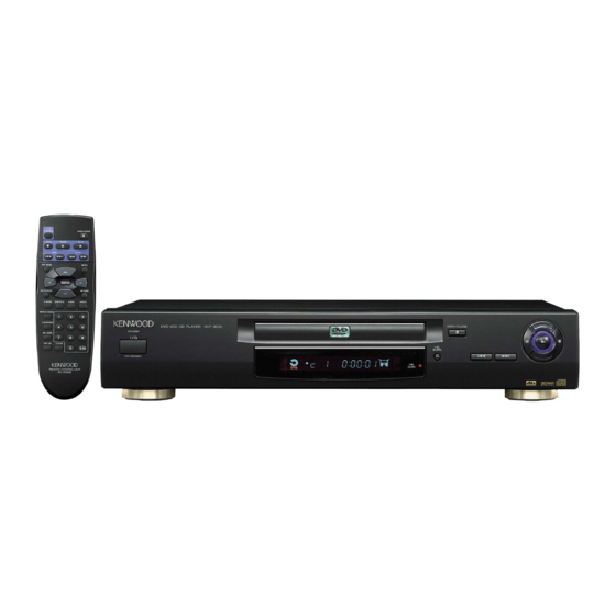
DVD VCD CD PLAYER
DVF-3030
SERVICE MANUAL
Legx4
(J02-1468-08)
Top cover *
(A01-)
DIGITAL OUTPUT
(PCM/BIT STREAM)
OPTICAL
In compliance with Federal Regulations, following are repro-
duction of labels on, or inside the product relating to laser
product safety.
KENWOOD-Crop. certifies this equipment conforms to DHHS
Regulations No.21 CFR 1040. 10, Chapter 1, subchapter J.
DANGER : Laser radiation when open and interlock defeated.
AVOID DIRECT EXPOSURE TO BEAM.
Tray top *
(A29-)
Y/C connector
(E40-8534-08)
AUDIO OUTPUT
VIDEO OUTPUT
L
S-VIDEO
R
SUB WOOFER
Pin jack
(E63-1170-08)
Caution : No connection of ground line if disassemble
NOTE : Please use the remote controller
© 2000-6/B51-5645-00 (K/K) 1405
Holder P
(J19-6058-08)
Connector (21P)
(E40-8598-08)
AV
* Refer to parts list on page 61.
the unit. Please connect the ground line on
rear panel, PCBs, Chassis and some others.
for self-diagnosis.
Front panel *
(A60-)
AC IN~
AC inlet *
(E40-)
70%
Advertisement

Related Manuals for Kenwood DVF-3030


Summary of Contents for Kenwood DVF-3030
- Page 1 PCBs, Chassis and some others. NOTE : Please use the remote controller KENWOOD-Crop. certifies this equipment conforms to DHHS Regulations No.21 CFR 1040. 10, Chapter 1, subchapter J. for self-diagnosis. DANGER : Laser radiation when open and interlock defeated.
-
Page 2: Table Of Contents
DVF-3030 CONTENTS / ACCESSORIES Contents CONTENTS / ACCESSORIES ........2 PARTS DESCRIPTIONS ..........24 DISASSEMBLY FOR REPAIR........3 PC BOARD .............. 25 BLOCK DIAGRAM ............12 SCHEMATIC DIAGRAM .......... 31 CIRCUIT DESCRIPTION ..........16 EXPLODED VIEW ............58 ADJUSTMENT ............18 PARTS LIST..............61 VOLTAGE CHART............19 SPECIFICATIONS ........Back cover WIRING DIAGRAM ...........23... -
Page 3: Disassembly For Repair
DVF-3030 DISASSEMBLY FOR REPAIR 1. Assembling and Disassembling the Casing 1-4 Disassembling the Front Panel and Checking C.B.A.s 1. Release the 3 tabs on the bottom. 2. Release the 2 tabs on the left and right. 1-1 Casing Parts and C.B.A. Positions Module C.B.A. - Page 4 DVF-3030 DISASSEMBLY FOR REPAIR 1-6 Checking the Module C.B.A. 1. Remove the screws. 2. Release the two tabs on the left and right. 2. Connect the module C.B.A. to the mother C.B.A. with the 1-8 Checking the Power Supply C.B.A.
- Page 5 DVF-3030 DISASSEMBLY FOR REPAIR 1-9 Checking the Mother C.B.A. 2. Assembling and Disassembling the Optical Pickup (Mechanical Parts) 1. Remove the 4 screws. 2. Release the 2 tabs. The optical pickup can be damaged by static electricity from your body. Be sure to take static electricity countermeasures when working around the optical pickup.
- Page 6 DVF-3030 DISASSEMBLY FOR REPAIR 2-3 Static Electricity Countermeasures 2-4 Disassembling the Clamp Base Unit The laser diode inside the traverse unit (optical pickup) can Remove the 2 screws. be damaged by static electricity from your body. Be sure to take static electricity countermeasures when working around the optical pickup.
- Page 7 DVF-3030 DISASSEMBLY FOR REPAIR 2-6 Disassembling the Traverse Unit 2-7 Disassembling the Stepping Motor Unit 1. Remove the 3 screws. 1. Disconnect the flexible cable. 2. Remove the 2 screws. Note Take care when handling the flexible cable because it can be broken by excessive force.
- Page 8 DVF-3030 DISASSEMBLY FOR REPAIR 2-9 Disassembling the Nut Unit 2-11 Assembling the Optical Pickup 1. Remove the screw. 1. Install the optical pickup. Notes Note Take care not ot attach the tilt spring and guide shaft in • The nut unit is not part of the optical pickup.
- Page 9 DVF-3030 DISASSEMBLY FOR REPAIR 3. Remove the solder from the pickup FPC's soldered short- 2-13 Optical Pickup Tilt Adjustment circuit. 4. Adjust the optical pickup tilt after removing the solder. (Refer to page 9/2-13 Optical Pickup Tilt Adjustment.) 2-12 Disassembling the Spindle Motor Unit 1.
- Page 10 DVF-3030 DISASSEMBLY FOR REPAIR Notes • Adjustment is generally unnecessary after replacing other parts of the traverse unit. However, adjust if there is a noticeable degradation in picture quality. • Optical adjustments cannot be made inside the optical pickup. • Adjustment is generally unnecessary after replacing the...
- Page 11 DVF-3030 DISASSEMBLY FOR REPAIR 2-14 Disassembling the Intermediate Chassis 2-16 Disassembling the Pulley Gear and Deceleration Gear 1. Push the stopper downward, then rotate it until it contacts the Vertical cam. 1. Remove the screw. 2. Release the 2 tabs.
- Page 16 1. Optical Pickup Self-Diagnosis and Replacement Procedure 2. Self-Diagnosis Function and Service Modes 2-1 Service Mode Table The optical pickup self-diagnosis function and tilt adjustment check function have been newly added to this player. When The service modes can be activated by pressing various button combinations on the player and remote control unit. repairing, use the following procedure for effective Self-diagnosis and tilt adjustment.
- Page 17 2-4 Examples of Repairs Using Error Codes DVD disc (Include 75% color bar) Refer to this section when carrying out repairs. Error display Malfunction example F0** Disc, IC7001 F103 Disc, IC7001 F4FF IC6001 F500 Optical pickup, IC2001, IC5201, IC2511, IC2501 F501 IC2001, IC6201 F502...
-
Page 18: Adjustment
DVF-3030 ADJUSTMENT 1. Video Output (Luminance Signal) 3. Video Component Signal (CB) Output Confirmation Confirmation Do this adjustment after replacing a C.B.A. Do this adjustment after replacing a C.B.A. Measu Measurement point Mode Disc rement point Mode Disc DVD disc... -
Page 19: Voltage Chart
DVF-3030 VOLTAGE CHART 1. Voltage chart 1-1 Power supply C.B.A. Ref No. IC1101 IC1125 IC1151 MODE STOP 10.2 PLAY Ref No. Q1021 Q1051 Q1052 Q1061 Q1062 MODE STOP -8.6 10.2 -0.2 10.1 PLAY -8.6 10.1 -0.1 10.1 Ref No. Q1063... - Page 20 DVF-3030 VOLTAGE CHART Ref No. IC3001 MODE STOP PLAY Ref No. IC3001 MODE STOP PLAY Ref No. IC3001 MODE STOP PLAY Ref No. IC3001 MODE STOP PLAY Ref No. IC3001 MODE STOP PLAY Ref No. IC3001 MODE STOP PLAY Ref No.
- Page 21 DVF-3030 VOLTAGE CHART Ref No. IC6201 MODE STOP PLAY Ref No. IC6201 MODE STOP PLAY Ref No. IC6201 MODE STOP PLAY Ref No. IC6201 MODE STOP PLAY Ref No. IC6201 MODE STOP PLAY Ref No. IC6251 IC6301 MODE STOP PLAY Ref No.
- Page 22 DVF-3030 VOLTAGE CHART 1-3 Mother C.B.A. Ref No. IC2591 MODE STOP PLAY Ref No. IC3511 MODE STOP PLAY Ref No. IC3511 MODE STOP PLAY Ref No. IC4321 IC4471 MODE STOP -8.1 -8.1 PLAY -8.1 -8.1 Ref No. IC4781 IC4902 IC4911...
-
Page 24: Parts Descriptions
DVF-3030 PARTS DESCRIPTIONS... - Page 25 THE STRIPED FRAME INDICATES THE PRIMARY CIRCUIT TO DISTINGUISH CAUTION THE PRIMARY FROM THE SECONDARY CIRCUIT. PAY ATTENTION NOT TO RECEIVE AN ELECTRIC SHOCK DURING REPAIR AND SERVICE OF THE PRODUCTS. POWER SUPPLY C.B.A. PS1101 R1161 W004 W051 C1125 C1154 C1117 IC1101 R1106...
- Page 26 MODULE C.B.A. (1/2) C3231 C3228 C6501 C6255 IC3071 C3085 C6502 C6511 LB3204 LB3207 L6501 RA3009 LB6501 R6504 C3051 C6517 R6503 C6257 C3091 IC3081 K6504 LB6506 C3005 C3006 C3223 C6516 LB6504 C4215 C3071 C3008 C3072 C3073 C4214 C3034 QR4211 RA3203 RA3204 C3056 IC3061 C4217...
- Page 27 MODULE C.B.A. (2/2) TC3207 TC3203 TC3202 TP6251 TC4006 TC4005 TC4007 TC4013 TC4009 FL6251 C3230 TC3205 TP6252 TC4008 TC4010 R3071 C3075 C3076 L6502 C6506 TP6259 K6503 CP6507 FL6252 PS4201 PS3201 C6512 C6513 LB6507 C3014 C3013 C3009 C3007 K6521 TP6253 CP6506 CP6501 C3035 C3226 C6514...
- Page 28 SCART C.B.A. C3865 R3841 C3863 IC3853 12 9 R3838 R3842 R3840 C3864 C3851 J3871 AV1 C3819 R3875 R3876 R3877 R3836 C3817 C3862 C3812 C3814 C3852 R3858 R3839 R3879 R3878 R3835 C3874 LB3871 LB3872 LB3873 C3867 K3852 R3807 R3857 C3857 LB3874 R3834 R3874 Q3833...
- Page 29 The DC voltage is an actual reading measured with a high impedance type voltmeter with no signal input. The measurement value may vary depending on the measuring instruments used or on the product. DVF-3030 Y22-8332-70...
- Page 30 The DC voltage is an actual reading measured with a high impedance type voltmeter with no signal input. The mea- surement value may vary depending on the measuring instruments used or on the product. DVF-3030 Y22-8332-70...
- Page 31 The DC voltage is an actual reading mea- sured with a high impedance type volt- meter with no signal input. The measure- ment value may vary depending on the measuring instruments used or on the product. DVF-3030 Y22-8332-70...
- Page 32 AD SECTION: (4/7), FEP SECTION: (5/7), CPU SECTION: (6/7), ODC SECTION: (7/7) CAUTION: For continued safety, replace safety critical components only with manufacturer's recom- The DC voltage is an actual reading measured with a DVF-3030 mended parts (refer to parts list). indicates safety critical components. For continued protection high impedance type voltmeter with no signal input.
- Page 33 The DC voltage is an actual reading measured with a high impedance type voltmeter with no signal input. The measurement value may vary depending on the measuring instruments used or on the product. DVF-3030 Y22-8332-70...
- Page 34 The DC voltage is an actual reading measured with a high impedance type voltmeter with no signal input. The measurement value may vary depending on the measuring instruments used or on the product. DVF-3030 Y22-8332-70...
- Page 35 The DC voltage is an actual reading mea- sured with a high impedance type voltmeter with no signal input. The measurement value may vary depending on the measuring instru- ments used or on the product. DVF-3030 Y22-8332-70...
- Page 36 The DC voltage is an actual reading measured with a high impedance type voltmeter with no signal input. The measurement value may vary depending on the measuring instruments used or on the product. DTA123JK 2SD1328 UN4213 UN5213 2SC3311A-R 2SB1218A UPC1093J NJM4558M UN5212 BA5983FM DVF-3030 Y22-8332-70...
- Page 37 The DC voltage is an actual reading measured with a high impedance type voltmeter with no signal input. The measurement value may vary depending on the measuring instru- ments used or on the product. DVF-3030 Y22-8332-70...
- Page 38 The DC voltage is an actual reading measured with a high impedance type voltmeter with no signal input. The measurement value may vary depending on the measuring instru- ments used or on the product. DVF-3030 Y22-8332-70...
- Page 39 The DC voltage is an actual reading measured with a high impedance type voltmeter with no signal input. The measurement value may vary depending on the measuring instru- ments used or on the product. DVF-3030 Y22-8332-70...
- Page 40 The DC voltage is an actual reading measured with a high impedance type voltmeter with no signal input. The measurement value may vary depend- ing on the measuring instruments used or on the product. DVF-3030 Y22-8332-70...
- Page 41 The DC voltage is an actual reading measured with a high impedance type voltmeter with no signal input. The measurement value may vary depend- DVF-3030 ing on the measuring instruments used or on the product. Y22-8332-70...
-
Page 43: Exploded View
DVF-3030 EXPLODED VIEW (MECHANISM) Parts with exploded numbers larger than 700 are not supplied. - Page 44 DVF-3030 EXPLODED VIEW (MECHANISM) MODULE C.B.A.(17P) MODULE C.B.A.(17P) Parts with exploded numbers larger than 700 are not supplied.
- Page 45 S6401 D6401 S6403 OPEN/CLOSE VIR.SURR. S6402 S6407 S6404 S6405 STANDBY D6411 POWER S6411 ON/STANDBY : N09-5149-08 B1’ : N09-5183-08 : N09-5150-08 : N09-5150-08 : N09-5153-08 2.6x10 : N09-5157-08 3x12 : N09-5154-08 3x20 : N09-5189-08 3x25 : N09-5156-08 : N09-5236-08 DVF-3030...
- Page 46 Description Ref. No Parts No. Description ress Parts nation marks nation marks ress Parts C1003 C90-3915-08 CERAMIC 0.001UF DVF-3030 K,E:BLACK PANEL ES,X:SILVER PANEL C1003,04 C90-3914-08 CERAMIC 470PF EESX ✽ C1005 C90-3892-08 MF-C 2200PF ✽ A01-3785-08 TOP COVER VGM1725 C1005 C90-3920-08...
- Page 47 ✽ New Parts ✽ New Parts Parts without Parts No. are not supplied. Parts without Parts No. are not supplied. Les articles non mentionnes dans le Parts No. ne sont pas fournis. Les articles non mentionnes dans le Parts No. ne sont pas fournis. Teile ohne Parts No.
- Page 48 ✽ New Parts ✽ New Parts Parts without Parts No. are not supplied. Parts without Parts No. are not supplied. Les articles non mentionnes dans le Parts No. ne sont pas fournis. Les articles non mentionnes dans le Parts No. ne sont pas fournis. Teile ohne Parts No.
- Page 49 ✽ New Parts ✽ New Parts Parts without Parts No. are not supplied. Parts without Parts No. are not supplied. Les articles non mentionnes dans le Parts No. ne sont pas fournis. Les articles non mentionnes dans le Parts No. ne sont pas fournis. Teile ohne Parts No.
- Page 50 ✽ New Parts ✽ New Parts Parts without Parts No. are not supplied. Parts without Parts No. are not supplied. Les articles non mentionnes dans le Parts No. ne sont pas fournis. Les articles non mentionnes dans le Parts No. ne sont pas fournis. Teile ohne Parts No.
- Page 51 ✽ New Parts ✽ New Parts Parts without Parts No. are not supplied. Parts without Parts No. are not supplied. Les articles non mentionnes dans le Parts No. ne sont pas fournis. Les articles non mentionnes dans le Parts No. ne sont pas fournis. Teile ohne Parts No.
-
Page 52: Mechanism Parts
✽ New Parts ✽ New Parts Parts without Parts No. are not supplied. Parts without Parts No. are not supplied. Les articles non mentionnes dans le Parts No. ne sont pas fournis. Les articles non mentionnes dans le Parts No. ne sont pas fournis. Teile ohne Parts No. -
Page 53: Parts List
This manual is based on Europe (E) standard, and provides information on regional circuit modification through use of alter- KENWOOD SERVICE CORPORATION nate schematic diagrams, and information on regional component variations P.O BOX 22745, 2201 East Dominguez St., Long Beach, CA 90801-5745, U.S.A.