Honeywell LYNX Touch L5200 Series Programming Manual
Hide thumbs
Also See for LYNX Touch L5200 Series:
- User manual (89 pages) ,
- Installation and setup manual (88 pages) ,
- Manual (24 pages)

Related Manuals for Honeywell LYNX Touch L5200 Series


Summary of Contents for Honeywell LYNX Touch L5200 Series
-
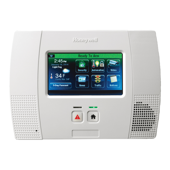
Page 1: Security System
LYNX Touch L5200/L7000 Series Security System Programming Guide 800-16086V1 12/14 Rev. A L5200CN/L7000CN... -
Page 2: Table Of Contents
Table of Contents Entering Programming Mode ............................ 3 Programming the Data Fields ........................... 3 Loading a Default Set ..............................3 Exiting Programming Mode ............................3 Data Fields ................................4 Change Installer Code ............................4 Program System Type ............................4 Program Date and Time ............................5 Program Communications ............................. -
Page 3: Entering Programming Mode
Entering Programming Mode You may find it convenient to adjust the volume setting before entering the Programming Mode. This will allow you to clearly hear feedback announcements or system beeps. 1. Power-up the control and allow it to “boot-up”. “System Standby” is displayed on the touch screen. When the “boot-up”... -
Page 4: Data Fields
Screen Display Function & Programming Options DATA FIELDS Note: If applicable, preprogrammed defaults for the LYNX Touch Control are shown on the screen display. Change Installer Code Installer Code Installer Code Enter 4 digits [The defaulted Installer Code 4112 is displayed on the left side of the screeen] 5000-100-129-V0 Program System Type RF Jam... -
Page 5: Program Date And Time
Screen Display Function & Programming Options Non Security Non Security Enabled Disabled Disabled Remote Access Serial Remote Access Serial Enabled Disabled Disabled Note: If the “Remote Access Serial” option is enabled, you will be prompted to select a “Multi Mode Serial”. -
Page 6: Program Communications
Screen Display Function & Programming Options Start Week End Week First First Second Third Fourth Last Next to Last 3rd from Last Program Communications Communicator Program the following options: Communicator Communications Path City ID CS ID Sub ID 5000-100-132-V0 Supervision Old Alarm Time Remote Acc. -
Page 7: Program Zones
Screen Display Function & Programming Options IP Fault Time (min) (displayed if IP or WiFi is selected as Communications Path) IP Fault Time (min) Enter 2-digits 00-99 Use DHCP Use DHCP Note: If No is selected the following options will be active NIC IP Address (Appears only if “no”... - Page 8 Screen Display Function & Programming Options Serial Number Serial Number When “Serial Number” has been selected “Enter Serial Number or Activate” is displayed. The transmitter serial number and loop number can be enrolled via RF transmission OR manually. Enroll via RF Learning To enroll the device using RF Learning mode three transmissions (open/close) of the device will be required.
-
Page 9: Program Keys
Screen Display Function & Programming Options Program Keys Keys Keys Select from the following options: Edit Add New Delete If add new is selected the following options can be programmed: Key Type User Serial Number Zone Button Key 1 – Zn 140 Button Key 2 –... - Page 10 Screen Display Function & Programming Options Phone Type Phone Type None Contact Id: 4 Digit Contact Id : 4 Digit Contact Id : 10 Digit Note: If SIA, Contact Id: 4 Digit, or Contact Id: 10 Digit is selected the Phone Number and Account Number options will be displayed.
- Page 11 Screen Display Function & Programming Options Communicator Type Communicator Type None None WiFi WiFi & GSM Note: If IP is selected the Dynamic Priority option will be displayed. Phone Number Phone Number Enter the Secondary Central Station Phone Number (Up to 20 digits) Communicator Type Communicator Type None...
- Page 12 Screen Display Function & Programming Options Phone Type (This feature is not available on the LYNX Touch L7000CN) Phone Type None None Follow me Phone Number (This feature is not available on the LYNX Touch L7000CN) Phone Type Enter the Follow Me Phone Number None Report All (This feature is not available on the LYNX Touch L7000CN) Report All...
- Page 13 Screen Display Function & Programming Options Report Selection Report Selection Choose from the following options: Arm Away Arm Stay Bypass Bypass Restore Disarm Exit Error AC Loss AC Loss Restore Recent Closing Event Log Full Low Battery Low Battery Restore Trouble Trouble Restore RF Low Battery...
- Page 14 Screen Display Function & Programming Options Enabled Enabled Low Battery Restore Low Battery Restore Disabled Enabled Enabled RF Low Battery RF Low Battery Disabled Enabled Enabled RF Low Battery Restore RF Low Battery Restore Disabled Enabled Enabled Options Choose from the following options: Options Call Wait Cancel Number of Reports...
-
Page 15: Program Sounder
Screen Display Function & Programming Options Callback Number Callback Number Enter a Callback Number Flexible Callback Flexible Callback (If Yes is selected the Number Option will be displayed.) Number (displayed if Flexible Callback is set to “Yes”) Number Enter the number of flexible callbacks that will be used (1-3) Program Sounder Sounder Choose from the following options:... -
Page 16: Program System Settings
Screen Display Function & Programming Options Program System Settings System Settings System Settings Choose from the following options: Entry Delay 1 Entry Delay 1 Exit Delay Backlight Timeout Quick Arm Quick Exit Restart Exit Time Force Bypass Exit Warning Auto Stay Arming Lack of Usage Notify Power-up in Previous Display Alarm Cancel... -
Page 17: Program The Z-Wave Module
Screen Display Function & Programming Options Lack of Usage Notify Lack of Usage Notify Disabled Disabled 1 Day 7 Days 27 Days 90 Days 180 Days 365 Days Power-Up in Previous State Power-Up in Previous Display Alarm Cancel Display Alarm Cancel Display Exit Time Display Exit Time Cross Zone Delay... -
Page 18: Communication Diagnostics
Communications Diagnostics Note: For additional information regarding these fields, refer to the LYNX Touch Installation and Setup Guide P/N 800-16082 or higher. Communication Diagnostics Comm. Diagnostics Choose from the following options (depending upon the Communication Module that is installed: Communication Ethernet Status Information... -
Page 19: Communications Diagnostics
Communications Diagnostics Test Communication - Performs network diagnostics and sends test alarms to the network. The following tests are available depending on the type of communications module installed. Message Function Send Cellular Message: Available if Cellular communication path is enabled Test Ethernet: Available if IP or WiFi communication path is enabled Send Ethernet Message:... -
Page 20: Zone Programming Worksheet
Zone Programming Worksheet Fill in the required data on this worksheet, then follow the programming procedure. (The defaults shown are for Configuration 1) See Explanation of Zone Assignment Table Headings Note: Zones 65-70, 156-163, and 186-187 are only available on the LYNX Touch L7000CN control. Zone Loop Device... - Page 21 Zone Programming Worksheet Zone Loop Device Response Transmitter Zone Type Type Report Chime Supervision Night Serial Number Descriptor Not Used Standard Supervised Main Not Used Standard Supervised Main Not Used Standard Supervised Main Not Used Standard Supervised Main 4 Button Arm Away Disabled Button...
-
Page 22: Explanation Of Zone Assignment Table Headings
Zone Programming Worksheet Zone Loop Device Response Transmitter Zone Type Type Report Chime Supervision Night Serial Number Descriptor Temperature Monitor Disabled High Temp Monitor Temperature Disabled Low Temp Monitor Temperature Disabled High Temp Monitor Temperature Disabled Low Temp Monitor Temperature Disabled High Temp Monitor... -
Page 23: 5800 Series Transmitter Loop Numbers Diagram
5800 Series Transmitter Loop Numbers LOOP 1 LOOP 1 (LOW (LOW SENSITIVITY SENSITIVITY LOOP LOOP 2 LOOP 2 (HIGH (HIGH LOOP 1 SENSITIVITY) SENSITIVITY) LOOP LOOP 3 (TEMP) LOOP 3 (TEMP) LOOP 4 (TAMPER) LOOP 4 (TAMPER) 5 8 0 0 C O 5 8 0 0 M i c r a 5 8 0 0 P I R - R E S 5 8 0 0 P I R / 5 8 0 0 P I R - C O M... -
Page 24: Lynx Touch L5200Cn Programming Default Values
L5200CN Programming Default Values Program Function Configuration 1 Configuration 2 Configuration 3 Configuration 4 Installer Code 4112 4112 4112 4112 System Type RF Jam Disabled Disabled Disabled Disabled Speaker Phone Disabled Disabled Disabled Disabled Two Way Voice Disabled Disabled Disabled Disabled RF House Code Phone Notification... - Page 25 Program Function Configuration 1 Configuration 2 Configuration 3 Configuration 4 Phone Number Blank Blank Blank Blank Account Number FFFF FFFF FFFF FFFF Dynamic Priority None None None None Dynamic Delay None None None None Report All Press to Report All Press to Report All Press to Report All Press to Report All...
- Page 26 Program Function Configuration 1 Configuration 2 Configuration 3 Configuration 4 Number Sounder Burglary Alarm Sound Burglary Bell Timeout 4 Minutes 4 Minutes 4 Minutes 4 Minutes Fire Bell Timeout 4 Minutes 4 Minutes 4 Minutes 4 Minutes Arm Confirm RF Keyfob RF Keyfob RF Keyfob RF Keyfob...
-
Page 27: Lynx Touch L7000Cn Programming Default Values
L7000CN Programming Default Values Program Function Configuration 1 Configuration 2 Configuration 3 Configuration 4 Installer Code 4112 4112 4112 4112 System Type RF Jam Disabled Disabled Disabled Disabled Speaker Phone Enabled Enabled Enabled Enabled Two Way Voice Disabled Disabled Disabled Disabled RF House Code Phone Notification... - Page 28 Program Function Configuration 1 Configuration 2 Configuration 3 Configuration 4 Communicator Type None None None None Phone Number Blank Blank Blank Blank Account Number FFFF FFFF FFFF FFFF Dynamic Priority None None None None Dynamic Delay None None None None Report All Press to Report All Press to Report All...
- Page 29 Program Function Configuration 1 Configuration 2 Configuration 3 Configuration 4 Callback Number Blank Blank Blank Blank Flexible Callback Number Sounder Burglary Alarm Sound Burglary Bell Timeout 4 Minutes 4 Minutes 4 Minutes 4 Minutes Fire Bell Timeout 4 Minutes 4 Minutes 4 Minutes 4 Minutes Arm Confirm...
- Page 30 - Notes - - 30 -...
-
Page 31: Lynx Touch Series Summary Of Connections Diagram
- 31 -... - Page 32 2 Corporate Center Drive, Suite 100 P.O. Box 9040, Melville, NY 11747 Copyright © 2014 Honeywell International Inc. www.honeywell.com/security Ê800-16086V1ZŠ 800-16086V1 12/14 Rev. A...