
Related Manuals for Honeywell HBD2PR1


Summary of Contents for Honeywell HBD2PR1
-
Page 1: User Guide
Embedded NVR Bundle IP Cameras HBD2PR1 H2D2PR1 User Guide Document 800-18161 – Rev A – 06/2014... - Page 3 User Guide...
- Page 4 Revisions Issue Date Revisions 06/2014 New document.
-
Page 5: Regulatory Statements
Cautions and Warnings WARNING To ensure compliance with electrical safety standards this product is intended for use with a Listed Power Adapter marked with “Limited Power Source”, “LPS”, on the unit, output rated 12 V DC, minimum 0.5A, Tma=60Deg.C or from Power over Ethernet (PoE) provided by Listed Information Technology Equipment meeting the IEEE 802.3af PoE standard. -
Page 6: Canadian Compliance Statement
Safety Instructions Before installing or operating the unit, read and follow all instructions. After installation, retain the safety and operating instructions for future reference. HEED WARNINGS - Adhere to all warnings on the unit and in the operating instructions. www.honeywell.com/security... - Page 7 INSTALLATION • Install in accordance with the manufacturer’s instructions. • Installation and servicing should be performed only by qualified and experienced technicians to conform to all local codes and to maintain your warranty. • Any wall or ceiling mounting of the product should follow the manufacturer’s instructions and use a mounting kit approved or recommended by the manufacturer.
- Page 8 8 | Embedded NVR Bundle IP Cameras User Guide www.honeywell.com/security...
-
Page 9: Table Of Contents
Overview ........... 27 Starting the Honeywell Configuration Tool........27 Installing the Quick Configuration Tool . - Page 10 Index ............101 www.honeywell.com/security...
- Page 11 Figure 1-3 HBD2PR1 Camera Dimensions ........25 Figure 1-4 HBD2PR1 Camera Components .
- Page 12 DDNS Configuration Interface ........62 Figure 3-24 Using Honeywell DDNS to Configure DDNS ......63 Figure 3-25 IP Filter Configuration Interface .
-
Page 13: Figures
Figures | 13 Figure 3-60 Alarm Configuration Interface ........92 Figure 3-61 Log In Interface . - Page 14 14 | Embedded NVR Bundle IP Cameras User Guide www.honeywell.com/security...
- Page 15 Table 1-3 HBD2PR1 Camera Components ........26 Table 3-1 Live View Window Sections.
- Page 16 16 | Embedded NVR Bundle IP Cameras User Guide www.honeywell.com/security...
-
Page 17: About This Document
About This Document This document introduces the Honeywell Embedded NVR Bundle IP Cameras. It covers how to install and operate the Embedded NVR Bundle IP Cameras. This document is intended for installers and users. Overview of Contents This document contains the following chapters and appendixes: •... -
Page 18: Related Documents
Describes the physical setup of a H2D2PR1 ball Ball IP Camera Quick Installation camera. Guide HBD2PR1 1080p True Day/Night IR 800-17077 Describes the physical setup of a HBD2PR1 ball Bullet IP Camera Quick Installation camera. Guide Embedded NVR User Guide 800-18160 Describes the embedded NVR, how to install it, how to configure it, and how to use it. - Page 19 | 19 Font What it represents Example Italic Placeholders: words that vary depending on the Enter your user name. situation Cross-reference to external source Refer to the Embedded NVR Quick Installation Guide. Cross-reference within document Chapter 2, Configuration. 800-18161 - A - 06/2014...
- Page 20 20 | Embedded NVR Bundle IP Cameras User Guide www.honeywell.com/security...
-
Page 21: Introduction
The Embedded NVR Bundle IP Cameras IP Cameras use standard H.264 video compression technology, which guarantees maximum video quality. Some of the Embedded NVR Bundle IP Cameras IP Cameras (H2D2PR1, HBD2PR1) support IR night vision. At night or in dimly environments, these cameras can use IR light to illuminate the scene. -
Page 22: Features Of The Embedded Nvr Bundle Ip Cameras
The Delay time is less than 270ms (network bandwidth support is required). • Supports a maximum of 20 connections. • Compatible with the following transmission protocols: HTTP, TCP, UDP, MULTICAST, RTP/RTCP, RTSP. • Supports web access. www.honeywell.com/security... -
Page 23: Camera Dimensions And Components
Introduction | 23 Table 1-1 IP Cameras Features Category Features Network Management • Supports network camera configuration and management via the Ethernet. • Supports device management via the Internet or through the client’s PC. Power • External 12 V DC adapter. •... -
Page 24: H2D2Pr1
24 | Embedded NVR Bundle IP Cameras User Guide H2D2PR1 Dimensions Figure 1-1 H2D2PR1 Camera Dimensions In millimeters Components Figure 1-2 H2D2PR1 Camera Components Table 1-2 H2D2PR1 Camera Components Name Function Lens Dome body www.honeywell.com/security... -
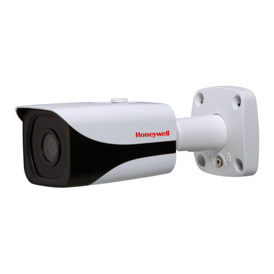
Page 25: Hbd2Pr1
H2D2PR1 Camera Components Name Function Dome camera enclosure Network port to connect to standard Ethernet. 12 V DC Connect 12 V DC HBD2PR1 Dimensions Figure 1-3 HBD2PR1 Camera Dimensions In millimeters Components Figure 1-4 HBD2PR1 Camera Components 800-18161 - A - 06/2014... - Page 26 26 | Embedded NVR Bundle IP Cameras User Guide Table 1-3 HBD2PR1 Camera Components Name Function Network port to connect to standard Ethernet. Note Before connecting to the RJ-45 port, pull the anti-dust cover over the network cable. 12 V DC Connect 12 V DC www.honeywell.com/security...
-
Page 27: Configuration
The Honeywell Configuration tool applies only to the IP addresses in the same segment. Starting the Honeywell Configuration Tool You must install the Honeywell Configuration Tool before you can use it to discover IP devices. 800-18161 - A - 06/2014... -
Page 28: Installing The Quick Configuration Tool
28 | Embedded NVR Bundle IP Cameras User Guide Installing the Quick Configuration Tool Insert the Software CD that came with your NVR into your PC. Navigate to and double-click Honeywell Config Tool to install the configuration tool software. The Honeywell Config Tool installation wizard opens. Figure 2-1 Honeywell Config Tool Wizard Click Next to begin the installation. -
Page 29: Figure 2-2 User License Agreement
Configuration | 29 Figure 2-2 User License Agreement Page Click to select I agree, and then click Install to install the software. The Installation is Complete page appears has been successful. Figure 2-3 Installation is Complete Page Click Enjoy Now to open and use the Config Tool. 800-18161 - A - 06/2014... -
Page 30: Opening The Honeywell Configuration Tool, Searching For Devices, And Opening A Web Client
30 | Embedded NVR Bundle IP Cameras User Guide Opening the Honeywell Configuration Tool, Searching for Devices, and Opening a Web Client In the Config Tool, you will find the IP addresses for the IP devices (NVRs and IP cameras). -
Page 31: Figure 2-6 Device Upgrade Login Interface
Configuration | 31 If you do not select a device before clicking Login, you will get a Connection Note Error message. Figure 2-6 Device Upgrade Login Interface Click OK. The Config Upgrade interface appears. Figure 2-7 Config Upgrade Interface Click OpenFile to select the upgrade file, and then click Upgrade to begin the upgrade. When the upgrade is complete, and the device is rebooting a Device is offline: [device IP address] message appears. -
Page 32: Figure 2-8 Device Offline Message
32 | Embedded NVR Bundle IP Cameras User Guide Figure 2-8 Device Offline Message Click OK to close the Device Offline warning message, and to return to the Upgrade interface. Figure 2-9 Upgrade Interface Log into the device again. www.honeywell.com/security... -
Page 33: Upgrading The Ip Cameras (Batch Upgrade)
Configuration | 33 If you do not select a device before clicking Login, you will get a Connection Note Error. Upgrading the IP Cameras (Batch Upgrade) Open the ConfigTool software if it is not already open. Figure 2-10 ConfigTool Login Click Upgrade to begin the batch upgrading process. -
Page 34: Figure 2-11 Upgrade Interface
Click Open to find and select the upgrade file. The Open interface appears. Figure 2-12 Open Interface Select the upgrade firmware, and then click Open or double-click the file to open it. The Open interface closes and you return to the Upgrade interface. www.honeywell.com/security... -
Page 35: Figure 2-13 Upgrade Interface
Configuration | 35 Figure 2-13 Upgrade Interface Click to select the devices you want to upgrade. Their row turns blue when selected. Click Upgrade to begin the batch upgrade. A message appears in the Upgrade State fields for each selected IP camera to show the batch upgrade progress. -
Page 36: Modifying The Ip Address
36 | Embedded NVR Bundle IP Cameras User Guide A message appears to show that the batch upgrade procedure is successful. Figure 2-15 Batch Upgrade Successful Message Modifying the IP Address Open the ConfigTool software if it is not already open. Figure 2-16 ConfigTool Login www.honeywell.com/security... -
Page 37: Figure 2-17 Selecting Net In The Configtool
Configuration | 37 Select from the list the device you want to modify. Click Login to log in to the device. Figure 2-17 Selecting Net in the ConfigTool Click Net to open the Net tab. Enter the new IP Address, and the corresponding Subnet Mask and Gateway. Click Save to save these new settings. - Page 38 38 | Embedded NVR Bundle IP Cameras User Guide www.honeywell.com/security...
-
Page 39: Web Operation
Web Operation This chapter includes: • Instructions for connecting to your camera over the Internet. • A description of the main Internet interface, and instructions on how to configure it. • Instructions about configuring the camera setup. Network Connection The Embedded NVR Bundle IP Cameras support Internet access and management through your PC. -
Page 40: Main User Interface
For example, if your camera’s IP address is 192.168.1.108, then please enter http://192.168.1.108 in the IE browser address bar. Figure 3-1 Logging in through an IE Browser Browser address bar The login window appears. Figure 3-2 Login Window Enter your username (default: admin) and password (default: 1234), then click Login. www.honeywell.com/security... -
Page 41: Figure 3-3 First Time Login Message
Web Operation | 41 Note For security reasons, please modify your password after you log in for the first time. If this is your first time to log in, you will see this message: Figure 3-3 First Time Login Message (If this is your first time logging in.) Click Please click here to download and install the plug-in. -
Page 42: Figure 3-4 File Download Security Warning Popup For The Plug-In
42 | Embedded NVR Bundle IP Cameras User Guide Figure 3-4 File Download Security Warning Popup for the Plug-in Click Run. An Internet Explorer - Security Warning appears. Figure 3-5 Internet Explorer - Security Warning Click Run to start this software. www.honeywell.com/security... -
Page 43: Live Interface
Web Operation | 43 Figure 3-6 Plug-in Installation Window Click Install. A progress window appears. Figure 3-7 Plug-in Installation Progress Window When the plug-in installation is complete, the installation page automatically closes. The web client automatically refreshes, and then you can view video from the camera. Live Interface When you log in, the Live interface appears. -
Page 44: Video Encoder Setup
Live View Window Sections Section Number Description Video encoder configuration bar System menu Window function option bar Live view window adjustment tool bar Video Encoder Setup Use the Video Encoder configuration bar to configure the main stream, sub stream, and protocols. www.honeywell.com/security... -
Page 45: System Menu
Web Operation | 45 Figure 3-9 Video Encoder Setup Bar Table 3-2 Live View Window Sections Parameter Function Main stream In a normal network bandwidth environment, the main stream can record audio/video files and support a network monitor. Set the main stream resolution if your camera supports it. Sub stream If the network bandwidth is not sufficient, you can use the sub stream to support a network monitor. -
Page 46: Configuring The Live View Window
Click to open the Help file. Video Window Configuration The video window configuration controls include these icons: Figure 3-12 Video Window Configuration Controls Table 3-4 Video Window Configuration Controls Icon Function Image Control Original Size Full Screen Width and Height Ratio Adjust Fluency www.honeywell.com/security... -
Page 47: Image Control
Web Operation | 47 Image Control Click to open the picture setup interface, which opens in the top right corner of the video interface. Figure 3-13 Image Adjustment Interface Table 3-5 Image Adjustment Controls Parameter Function Adjust the monitor’s Note brightness. -
Page 48: Width And Height Ratio
Fluent mode, there might be a decrease in the image quality, and possibly a delay in the video. Setup Camera Configuration Conditions On the Conditions tab, you can view camera property information. The configurations become valid immediately after they are saved. Figure 3-14 Camera Setup Window www.honeywell.com/security... - Page 49 Web Operation | 49 Table 3-6 Camera Configurations Parameter Function Profile Select from Normal, Day, Night. Brightness Adjusts monitor brightness. Choosing a higher value increases the video brightness. Adjustments to this value affects the brightness of the video. Select from 0 to 100. The recommended range is between 40 to 60.
- Page 50 Color: The camera outputs video in color. Auto: The camera switches from Color to Black & White according to the conditions, such as if the scene is generally bright, or if IR illumination is required. Black & White: The camera outputs black and white video. www.honeywell.com/security...
- Page 51 Web Operation | 51 Table 3-6 Camera Configurations Parameter Function BLC Mode Disables the BLC function. The default for BLC is that it is disabled. The camera automatically adjusts the exposure to suit the conditions, so that the darkest area of the video can be seen.
-
Page 52: Profile Management
When you make changes to the video configuration, you will immediately see the effects of those changes in the video. However, you must click Save to save and apply these settings. Video Configuration Video Bit Stream Figure 3-16 Video Bit Stream Configuration Window www.honeywell.com/security... - Page 53 Web Operation | 53 Table 3-7 Video Bit Stream Configurations Parameter Function Code-Stream Type Select from General stream and Motion stream. You can select different encoder frame rates for different recording events. The system supports the Active Control Frame (ACF) function. This allows you to record in different frame rates.
- Page 54 I Frame Interval Set the P-frame amount between two I frames. The value ranges from 25 to 150. The default is 50. The recommended value for Frame Rate is *2. www.honeywell.com/security...
-
Page 55: Snapshot
Web Operation | 55 Snapshot Figure 3-17 Snapshot Configuration Interface Table 3-8 Snapshot Configurations Parameter Function Shapshot Type Select from either General (schedule) or Event (activation). Image Size Same as the main stream resolution. Quality Select from six levels of image quality. Interval Set the snapshot frequency from 1s to 7s. -
Page 56: Video Overlay
Use the mouse to drag the time to the desired position. Location Enable this function so that the system overlays the customized location information in the video window. Use the mouse to drag the location information to the desired position. www.honeywell.com/security... -
Page 57: Path
Web Operation | 57 Path Figure 3-19 Storage Path Interface Set the storage path for snapshots ( in the live interface) and for recorded video ( the live interface). The default paths are C:\PictureDownload\ and C:\PictureRecord\. Note Shapshots are saved as bitmaps. Click Save to save any changes to the storage paths. -
Page 58: Network Configuration
IP/submask/gateway and DHCP are read-only when the PPPoE function is correctly working. MAC Address Displays the MAC address. IP Version Select the IP version, either IPV4 or IPV6. You can access the IP address of both of these versions. www.honeywell.com/security... - Page 59 Web Operation | 59 Table 3-10 TCI/IP Configuration Parameter Function IP Address Use the keyboard to enter the corresponding number to modify the IP Address, and then set the corresponding Subnet Mask and Default Gateway. Preferred DNS Enter the preferred DNS IP address. Server Alternate DNS Enter an alternate DNS IP address.
-
Page 60: Connection
The default is 37777. You can enter an actual port number, if necessary. UDP Port The default is 37778. You can enter an actual port number, if necessary. HTTP Port The default is 80. You can enter an actual port number, if necessary. www.honeywell.com/security... -
Page 61: Pppoe
Web Operation | 61 Table 3-11 Connection Configurations Parameter Function RTSP Port The default is 554. The RTSP stream query format is: Main stream: rtsp://username:password@ip:port/cam/realmonitor? channel=1&subtype=0 Sub stream: rtsp://username:password@ip:port/cam/realmonitor? channel=1&subtype=1 You are required to manually enter the following four items: username/password/IP, and port. -
Page 62: Ddns
You must go to the IP address to check the camera’s current information. You can access the web client through this address. DDNS Set the DDNS to connect the Honeywell DDNS server so that you can access the system through the servers. Manually Configuring the DDNS... -
Page 63: Figure 3-24 Using Honeywell Ddns To Configure Ddns
Parameter Function Server Type You can select the DDNS protocol from the drop-down list, and then enable the DDNS function. Select the Honeywell DDNS server (which is free) to enable the DDNS function. Server Address The DDNS server IP address. -
Page 64: Ip Filter
Before you can restrict access through the cameras through the IP filter, you must first configure the Trusted Sites here. Note You must add these addresses before enabling Trusted Sites. Note You must set the MAC address in the same network segment as the camera’s IP address. www.honeywell.com/security... -
Page 65: Smtp (Email)
Web Operation | 65 SMTP (Email) Figure 3-26 SMTP Configuration Interface Table 3-14 SMTP (Email) Configurations Parameter Function SMTP Server Enter the server address. Port The default value is 25. You can modify this value as necessary. Anonymity Supports the anonymity function for the server. You can automatically login anonymously. -
Page 66: Upnp
Before you can do an email test, you must save the email setup information. UPnP UPnP allows you to establish the mapping relationship between the LAN and the public network. In the UPnP configuration interface, you can add, modify, or remove a UPnP item. Figure 3-27 UPnP Configuration Interface www.honeywell.com/security... -
Page 67: Snmp
Web Operation | 67 Note For UPnP on different routers, you must disable the UPnP function. Enabling UPnP in Windows If UPnP is enabled in the Windows operating system, then the network can automatically detect the camera through My Network Places. Go to Start>Control Panel>Add or remove programs. -
Page 68: Figure 3-28 Snmp Configuration Interface
PC in the LAN. It is a non-protocol connection port. It has no effect on the network applications. It is a UDP port not a TCP port. The value ranges from 1 to 65535. The default is 162. www.honeywell.com/security... -
Page 69: Bonjour
Web Operation | 69 Table 3-15 SNMP Configurations Parameter Function SNMP Version SNMP v1: The system only processes v1 information. SNMP v2: The system only processes v2 information. SNMP v3: You can set the user name and password. There is account security verification when the server wants to connect to the camera. -
Page 70: Multicast
CPU load. The source host can send out just one data packet. This function depends on the relationship between group members and the router’s group. In the Multicast configuration interface, you can set the multicast address and port. Note You also need to go to the Live interface to set the protocol to Multicast. www.honeywell.com/security... -
Page 71: Ieee802.1X
Web Operation | 71 Figure 3-30 Mulitcast Configuration Interface Table 3-16 Multicast Configurations Parameter Function Enable Select to enable the multicast function. Main stream and sub stream can not be used at the same time. Multicast Address The main/sub stream multicast address is 239.255.42.42 and its range is 224.0.0.0~239.255.255.255. -
Page 72: Qos
It can select different queues according to the priority of the packets, and select the bandwidth for each queue. It can also select different ratios to discard if the bandwidth is overloaded. www.honeywell.com/security... -
Page 73: Figure 3-32 Qos Configuration Interface
Web Operation | 73 Figure 3-32 QoS Configuration Interface Table 3-18 QoS Configurations Parameter Function Realtime Monitor This value ranges from 0 to 63. The router or the switcher can provide different service for different packets. Command This value ranges from 0 to 63. The router or the switcher can provide different service for different packets. -
Page 74: Events
When this function is enabled, the system sends an email alert to you when an alarm occurs. Snapshot Check to enable the system to backup motion detection snapshot files. (See Path on page 57 for information about configuring where snapshots are saved.) www.honeywell.com/security... -
Page 75: Figure 3-34 Configuring The Working Period
Web Operation | 75 Configuring the Working Period Figure 3-34 Configuring the Working Period 800-18161 - A - 06/2014... -
Page 76: Figure 3-35 Configuring The Motion Detection Area
You can configure up to four areas. The sensitivity ranges from 0 to 100. We recommend that you choose a sensitivity between 10 to 50. Delete All Delete all motion detection areas. Delete Delete the selected motion detection area. www.honeywell.com/security... -
Page 77: Tampering
Web Operation | 77 Tampering Figure 3-36 Tampering Configuration Interface Table 3-21 Tampering Configurations Parameter Function Enable Check to enable the Tampering function. Working Period The video masking feature is activated during the specified period. Tampering Working Period Configuration Interface on page You can configure up to six periods per day. -
Page 78: Abnormality
78 | Embedded NVR Bundle IP Cameras User Guide Figure 3-37 Tampering Working Period Configuration Interface Abnormality There are two statuses: Disconnection and IP Conflict. Figure 3-38 Disconnection Configuration Interface Figure 3-39 IP Conflict Configuration Interface www.honeywell.com/security... -
Page 79: Storage
Web Operation | 79 Storage Recording Schedule and Snapshot Schedule You can add or remove schedules for recording and snapshots. There are two recording modes: General (auto) and Motion Detection. You can configure up to six recording periods per day. Note Ensure that you have enabled the corresponding recording mode in Setup>Storage>Conditions. -
Page 80: Destination
The event type corresponds with the two modes (general/motion) in the Schedule interface. Check the box to enable. Figure 3-42 Destination Configuration Interface Table 3-22 Destination Configurations Parameter Function Event Type Including Scheduled and Motion Detect. Select to save in the FTP server. Click FTP to open the FTP tab. www.honeywell.com/security... -
Page 81: Record Control
Web Operation | 81 Figure 3-43 FTP Configuration Interface Check to enable FTP. When enabled, event-triggered (either scheduled or motion detection, depending on what you chose in Figure 3-42) video and snapshots will be saved to the FTP. Record Control Figure 3-44 Record Control Configuration Interface Table 3-23... -
Page 82: System
General Figure 3-45 General System Configuration Interface Table 3-24 General System Configurations Parameter Function Device Name Enter the camera’s name. Language Select a language from the drop-down list. Video Standard Select the video standard, either NTSC or PAL. www.honeywell.com/security... -
Page 83: Figure 3-46 Date And Time Configuration Interface
Web Operation | 83 Date and Time Figure 3-46 Date and Time Configuration Interface Table 3-25 Date and Time Configurations Parameter Function Date Format Select a date format from the drop-down list. Time Format Select a time format, either 24-hour or 12-hour. Time Zone Select the time zone for the camera. -
Page 84: Accounts
Enable Anonymous Login: Click to enable. When you enter an IP, no username or password is required. You can log in anonymously (with limited rights). Click Logout to end your anonymous session. Add User: Add a user to a group and configure that user’s rights. www.honeywell.com/security... - Page 85 Web Operation | 85 Figure 3-48 Add User Configuration Interface There are four types of default user: • admin • 888888 • 666666 • hidden user "default" All user types except 666666 have administrator rights. 666666-type users have only monitoring rights.
-
Page 86: Figure 3-49 Modifying User Interface
Click Save to save the new settings. Note Passwords can contain up to 32 characters, using numbers and letters only. Only users with account rights can modify other users’ passwords. Group In the Group configuration interface, you can add/remove groups and modify group passwords. www.honeywell.com/security... -
Page 87: Figure 3-50 Group Configuration Interface
Web Operation | 87 Figure 3-50 Group Configuration Interface Adding a Group: Add a group and configure that group’s rights. Enter the group name, and then check the box to select the corresponding rights, including live (view), record control, and account. -
Page 88: Default
In the Modify Group Interface, you can edit Remarks and Rights. Default Click Default to restore the camera to the factory preset settings. Figure 3-53 Default Interface Note The system can not reset some information, such as the network IP address. www.honeywell.com/security... -
Page 89: Import/Export
Web Operation | 89 Import/Export Figure 3-54 Import/Export Configuration Interface Table 3-26 Import/Export Configurations Parameter Function Import Click to import local setup files to the system. Export Click to export the corresponding system setup to your local PC. Automatic Maintenance You can select either Auto Reboot or Manual Reboot. -
Page 90: Upgrade
Selecting the incorrect upgrade file might cause a camera malfunction. Information Version In the Version interface, you can view the system hardware features, the software version, and the release date. This information is for reference only; it is not configurable. Figure 3-57 Version Interface www.honeywell.com/security... -
Page 91: Log
Web Operation | 91 Figure 3-58 Log Interface Table 3-27 Log Interface Configurations Parameter Function Start Time Configure the start time for the requested log. End Time Configure the end time for the requested log. Type Select a log type: System, Operation, Configuration Operation, Data Operation, Event Operation, Record Operation, Account Management, Log Clearing. -
Page 92: Alarm
Click the Alarm tab to open the alarm configuration interface. Figure 3-60 Alarm Configuration Interface Table 3-28 Alarm Configurations Type Parameter Function Motion Detection System alarms when a motion detection alarm Alarm Type occurs. Tampering System alarms when the camera has been tampered with. www.honeywell.com/security... -
Page 93: Log Out
Web Operation | 93 Table 3-28 Alarm Configurations Type Parameter Function Operation Prompt System pops up an alarm dialog box. Play Alarm Tone When an alarm occurs, the system automatically Alarm Tone generates an audible sound. You can select a tone from your PC for the alarm tone prompt. - Page 94 94 | Embedded NVR Bundle IP Cameras User Guide www.honeywell.com/security...
-
Page 95: Appendix A Troubleshooting
Troubleshooting Table A-1 Troubleshooting Problem Possible Cause/Solution I can not boot up Click and hold RESET for at least five seconds to restore the the camera or camera’s factory default settings. operate it properly Water leakage Check the front glass cap or rear waterproof cap. Removing or occurred loosening the front or rear cap could result in water leakage. - Page 96 The general power adapter can work ranging from 0°C to 40°C. The camera might experience an unstable power supply when the temperature exceeds the working temperature. Please replace with an industry-level power adapter if you are using in cold-weather environments. We recommend that you use a UPS power adapter. www.honeywell.com/security...
-
Page 97: Appendix B Specifications
1920 (H) × 1080 (V) Minimum Illumination 0.5 Lux @ F1.6 (Color); 0 Lux @ F1.6 (IR LEDs on) Maximum IR LEDs H2D2PR1: 20 m length HBD2PR1: 30 m Video Output S/N Ratio More than 50 db Gain Control Auto / Manual... - Page 98 Power Consumption 6 W maximum Mechanical Dimensions H2D2PR1: Ø4.5 x 3.4 inches (Ø114 x 86 mm) HBD2PR1: 6.6 x 2.6 x 2.3 inches (168.1 x 66.0 x 58.4 mm) Weight H2D2PR1: 0.64 pounds (0.29 kg) HBD2PR1: 1.10 pounds (0.5 kg) Construction...
- Page 99 Specifications | 99 Table B-1 Specifications Security Up to 20 users, multiple user access levels with password protection Operating System CPU Requirements System Memory Network Card RJ-45 (10/100 Base-T) ® ® Web Browser Microsoft Internet Explorer 6.0 or later; Mozilla Firefox ®...
- Page 100 100 | Embedded NVR Bundle IP Cameras User Guide www.honeywell.com/security...
-
Page 101: Index
| 101 Index Numerics auto exposure 3D noise reduction 3DNR default backup 802.1 batch upgrading cameras authentication bit rate password configuration username type bit rate type configuration bitmap BLC mode camera configuration abnormality Bonjour accounts brightness maximum number of configurations button active control frame full-screen... - Page 102 DDNS server address recording destination DDNS server type recording mode DDNS update period recording schedule DDNS username recording stream DDNS using Honeywell DDNS reference bit stream DDNS, manually resolution default gateway resolution configuration destination RTSP port destination recording event type...
- Page 103 DDNS server address system settings encryption type system time format ethernet port system time zone system update period Honeywell DDNS server address tampering detection HTTP port tampering recording HTTPs tampering recording delay I-frame interval tampering send email I-frame rate...
- Page 104 Honeywell DDNS 62, protocol host name encoder mode configuration HTTP encryption port configuration password port default type HTTPs default type default encryption mode, configuring...
- Page 105 | 105 IPV6 port server NTSC number of connections, maximum number of network LAN port 25, monitor language live view recording snapshot online user triple snap overwriting zoom live view window live view window adjustment tool bar pack duration location pack duration default backup password...
- Page 106 74, tool bar storage path live view window adjustment type transmission protocols trap SNMP authentication password address authentication type port www.honeywell.com/security...
- Page 107 | 107 triple snap area sensitivity trusted sites area threshold, area threshold for VMD configuring events configuring working period 74, detection area 74, UDP port recording configuration recording delay default sending emails update period 66, sensitivity upgrading software sensitivity default UPnP snapshot settings configurations...
- Page 108 108 | Embedded NVR Bundle IP Cameras User Guide www.honeywell.com/security...
- Page 110 Document 800-18161 – Rev A – 06/2014 © 2014 Honeywell International Inc. All rights reserved. No part of this publication may be reproduced by any means without written permission from Honeywell. The information in this publication is believed to be accurate in all respects. However, Honeywell cannot assume responsibility for any consequences resulting from the use thereof.