Table of Contents
Advertisement
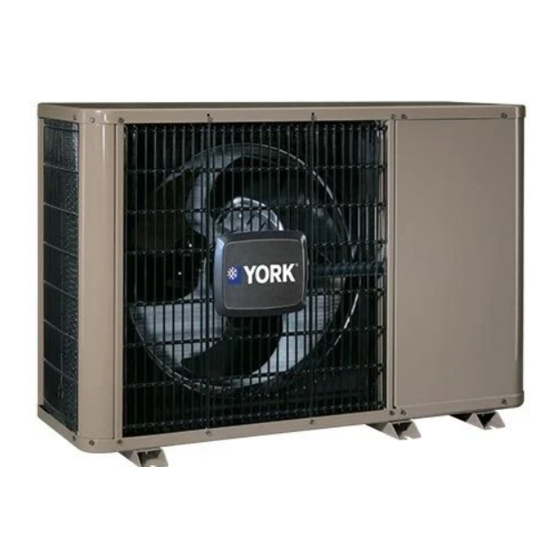
INSTALLATION MANUAL
R-410A
HORIZONTAL DISCHARGE
AIR CONDITIONING
MODELS: 13 SEER
YCHD/TCHD SERIES
1.5 TO 5 TONS - 1 & 3 PHASE
GENERAL . . . . . . . . . . . . . . . . . . . . . . . . . . . . . . . . . . . . . . . . . . . . . .1
SAFETY . . . . . . . . . . . . . . . . . . . . . . . . . . . . . . . . . . . . . . . . . . . . . . . .1
UNIT INSTALLATION . . . . . . . . . . . . . . . . . . . . . . . . . . . . . . . . . . . . .2
TXV INSTALLATION . . . . . . . . . . . . . . . . . . . . . . . . . . . . . . . . . . . . . .5
EVACUATION . . . . . . . . . . . . . . . . . . . . . . . . . . . . . . . . . . . . . . . . . . .5
Typical Installation . . . . . . . . . . . . . . . . . . . . . . . . . . . . . . . . . . . . . . . .2
Installation of Vapor Line . . . . . . . . . . . . . . . . . . . . . . . . . . . . . . . . . . .3
Underground Installation . . . . . . . . . . . . . . . . . . . . . . . . . . . . . . . . . . .3
Heat Protection . . . . . . . . . . . . . . . . . . . . . . . . . . . . . . . . . . . . . . . . . .4
Outdoor Unit Field Wiring Control Box . . . . . . . . . . . . . . . . . . . . . . . . .6
Typical Field Wiring (Air Handler / Electrical Heat) . . . . . . . . . . . . . . .7
Application Limitations . . . . . . . . . . . . . . . . . . . . . . . . . . . . . . . . . . . . .2
SECTION I: GENERAL
The outdoor units are designed to be connected to a matching indoor
coil with sweat connect lines. Sweat connect units are factory charged
with refrigerant for a matching indoor coil plus 15 feet of field supplied
lines.
The refrigerant charge may need to be changed for some indoor-out-
door unit combinations, elevation differences or total line lengths. Refer
to Application Data covering "General Piping Recommendations and
Refrigerant Line Length" (Part Number 247077).
SECTION II: SAFETY
This is a safety alert symbol. When you see this symbol on
labels or in manuals, be alert to the potential for personal
injury.
Understand and pay particular attention to the signal words DANGER,
WARNING, or CAUTION.
DANGER indicates an imminently hazardous situation, which, if not
avoided, will result in death or serious injury.
WARNING indicates a potentially hazardous situation, which, if not
avoided, could result in death or serious injury.
CAUTION indicates a potentially hazardous situation, which, if not
avoided may result in minor or moderate injury. It is also used to
alert against unsafe practices and hazards involving only property dam-
age.
This product must be installed in strict compliance with the
enclosed installation instructions and any applicable local, state,
and national codes including, but not limited to building, electrical,
and mechanical codes.
LIST OF SECTIONS
SYSTEM CHARGE . . . . . . . . . . . . . . . . . . . . . . . . . . . . . . . . . . . . . . 5
ELECTRICAL CONNECTIONS . . . . . . . . . . . . . . . . . . . . . . . . . . . . . 6
INSTRUCTING THE OWNER . . . . . . . . . . . . . . . . . . . . . . . . . . . . . 12
WIRING DIAGRAM . . . . . . . . . . . . . . . . . . . . . . . . . . . . . . . . . . . . . 13
LIST OF FIGURES
Thermostat Chart - Single Stage AC with PSC Air Handler . . . . . . . . 8
Thermostat Chart - Single Stage AC with PSC Air Handler . . . . . . . . 9
Thermostat Chart - Single Stage AC with PSC Furnace . . . . . . . . . 10
Thermostat Chart - Single Stage AC with PSC Furnace . . . . . . . . . 11
Wiring Diagram . . . . . . . . . . . . . . . . . . . . . . . . . . . . . . . . . . . . . . . . . 13
LIST OF TABLES
R-410A Saturation Properties . . . . . . . . . . . . . . . . . . . . . . . . . . . . . . . 6
Improper installation may create a condition where the operation of
the product could cause personal injury or property damage.
Improper installation, adjustment, alteration, service or mainte-
nance can cause injury or property damage. Refer to this manual
for assistance or for additional information, consult a qualified con-
tractor, installer or service agency.
R-410A systems operate at higher pressures than R-22 systems.
Do not use R-22 service equipment or components on R-410A
equipment. Service equipment
INSPECTION
As soon as a unit is received, it should be inspected for possible dam-
age during transit. If damage is evident, the extent of the damage
should be noted on the carrier's delivery receipt. A separate request for
inspection by the carrier's agent should be made in writing. See Local
Distributor for more information.
Requirements For Installing/Servicing R-410A Equipment
• Gauge sets, hoses, refrigerant containers, and recovery system
must be designed to handle the POE type oils, and the higher
pressures of R-410A.
• Manifold sets should be 800 PSIG high side and 250 PSIG low
side with 550 PSIG low side retard.
• All hoses must have a 700 PSIG service pressure rating.
• Leak detectors should be designed to detect HFC refrigerant.
• Recovery equipment (including refrigerant recovery containers)
must be specifically designed to handle R-410A.
• Do not use an R-22 TXV.
• A liquid-line filter drier is required on every unit.
ISO 9001
Certified Quality
Management System
Must Be Rated
for R-410A.
406905-UIM-C-1009
Advertisement
Table of Contents

Related Manuals for York YCHD Series


Summary of Contents for York YCHD Series
-
Page 1: Table Of Contents
INSTALLATION MANUAL R-410A HORIZONTAL DISCHARGE AIR CONDITIONING MODELS: 13 SEER ISO 9001 Certified Quality YCHD/TCHD SERIES Management System 1.5 TO 5 TONS – 1 & 3 PHASE LIST OF SECTIONS GENERAL ..........1 SYSTEM CHARGE . -
Page 2: Unit Installation
406905-UIM-C-1009 LIMITATIONS If the unit is to be installed on a hot sun exposed roof or a black-topped ground area, the unit should be raised sufficiently above the roof or The unit should be installed in accordance with all National, State and ground to avoid taking the accumulated layer of hot air into the outdoor Local Safety Codes and the limitations listed below: unit. -
Page 3: Installation Of Vapor Line
406905-UIM-C-1009 GROUND INSTALLATION The unit should be installed on a solid base that is 2” above grade and will not shift or settle, causing strain on the refrigerant lines and possible This system uses R-410A refrigerant which operates at higher pres- leaks. -
Page 4: Heat Protection
406905-UIM-C-1009 TO OUTDOOR UNIT TO INDOOR COIL Liquid Line Insulated Vapor Line Conduit FIGURE 3: Underground Installation PRECAUTIONS DURING BRAZING OF LINES All outdoor unit and evaporator coil connections are copper-to-copper FIGURE 4: Heat Protection and should be brazed with a phosphorous-copper alloy material such as Silfos-5 or equivalent. -
Page 5: Txv Installation
406905-UIM-C-1009 12. Release the refrigerant charge into the system. Open both the liq- uid and vapor valves by removing the plunger cap and with an allen wrench back out counter-clockwise until valve stem just touches the chamfered retaining wall. If the service valve is a ball Schrader valve core MUST NOT be installed with TXV installation. -
Page 6: Outdoor Unit Field Wiring Control Box
406905-UIM-C-1009 SUBCOOLING CHARGING METHOD - TXV INDOOR Example: The liquid pressure listed at the intersection of the indoor For cooling operation, the subcooling values are shown in parentheses WB and the outdoor DB 320 psig. Pressure at the liquid valve is 305 on the charging charts provided with the unit. -
Page 7: Typical Field Wiring (Air Handler / Electrical Heat)
406905-UIM-C-1009 The complete connection diagram and schematic wiring label is located on the inside surface of the unit service access panel. Replace the corner cover removed in Step 2. High Voltage All field wiring to be in accordance with national electrical codes Wiring (NEC) and/or local-city codes. -
Page 8: Thermostat Chart - Single Stage Ac With Psc Air Handler
406905-UIM-C-1009 For additional connection diagrams for all UPG equipment refer to “Low Voltage System Wiring” document available online at www.upgnet.com in the Product Catalog Section. AC 1A Single Stage Air Conditioner – PSC Air Handler ID MODELS THERMOSTAT SINGLE STAGE SINGLE STAGE *PP11C70224 AIR HANDLER... -
Page 9: Thermostat Chart - Single Stage Ac With Psc Air Handler
406905-UIM-C-1009 AC 1B Single Stage Air Conditioner – PSC Air Handler ID MODELS THERMOSTAT THERMOSTAT *BP11C50124 SINGLE STAGE *BN11C01124 *BN11C00124 *DP11C40124 AIR HANDLER CONDITIONER *DN11C00124 SINGLE STAGE AIR HANDLER CONTROL AIR CONDITIONER 24 – Volt Common 24 – Volt Common 24 –... -
Page 10: Thermostat Chart - Single Stage Ac With Psc Furnace
406905-UIM-C-1009 AC 5D Single Stage Air Conditioner – Single Stage PSC Furnace ID MODELS G*(8/9)S GF(8/9) G*9F L(Y/M)8S TG(8/9)S THERMOSTAT (G/T)GLS SINGLE STAGE SINGLE STAGE *PP11C70224 FURNACE CONDITIONER SINGLE STAGE PSC SINGLE STAGE SINGLE STAGE FURNACE AIR CONDITIONER AIR CONDITIONER 24 –... -
Page 11: Thermostat Chart - Single Stage Ac With Psc Furnace
406905-UIM-C-1009 AC 5E Single Stage Air Conditioner – Single Stage PSC Furnace ID MODELS G*(8/9)S GF(8/9) G*9F L(Y/M)8S TG(8/9)S THERMOSTAT THERMOSTAT (G/T)GLS *BP11C50124 SINGLE STAGE SINGLE STAGE *BN11C01124 *BN11C00124 *DP11C40124 FURNACE CONDITIONER *DN11C00124 SINGLE STAGE PSC SINGLE STAGE FURNACE AIR CONDITIONER 24 –... -
Page 12: Instructing The Owner
406905-UIM-C-1009 SECTION VIII: INSTRUCTING THE OWNER 3. If the coil needs to be cleaned, use clean water to wash dust, dirt, and debris from outdoor condensing coil. Assist owner with processing warranty cards and/or online registration. Review Owners Guide and provide a copy to the owner and guidance on proper operation and maintenance. -
Page 13: Wiring Diagram
406905-UIM-C-1009 SECTION IX: WIRING DIAGRAM FIGURE 12: Wiring Diagram (Single-Phase) Johnson Controls Unitary Products... - Page 14 406905-UIM-C-1009 FIGURE 13: Wiring Diagram (Three-Phase) Johnson Controls Unitary Products...
- Page 15 406905-UIM-C-1009 NOTES Johnson Controls Unitary Products...
- Page 16 NOTES Subject to change without notice. Published in U.S.A. 406905-UIM-C-1009 Copyright © 2009 by Johnson Controls, Inc. All rights reserved. Supersedes: 406905-UIM-B-1008 Johnson Controls Unitary Products 5005 York Drive Norman, OK 73069...