
Related Manuals for Daewoo RD-430


![Home Theater System Daewoo HC-6120[U] Service Manual](https://static-data2.manualslib.com/product-images/5ac/816239/60x60/daewoo-hc-6120-u-home-theater-system.jpg)


Summary of Contents for Daewoo RD-430
- Page 1 SN: 9CD8305300 Service Manual DIGITAL HOME CINEMA SYSTEM RD-430 DAEWOO DAT CO., LTD. Dec. 2006...
-
Page 2: Table Of Contents
DIGITAL HOME CINEMA SYSTEM RD-430 Table of Contents SAFETY PRECAUTIONS ................1 SPECIFICATIONS ..................2 LOCATION OF USERS CONTROLS ............3 FRONT PANEL DISPLAY REAR PANEL REMOTE CONTROLLER CONNECTING TO EQUIPMENT ............... 4 CONNECTING TO TV CONNECTING TO SPEAKER CONNECTING THE SUPPLIED FM/AM(MW) ANTENNAS... -
Page 3: Safety Precautions
Safety Precautions WARNING: TO PREVENT FIRE OR ELECTRIC SHOCK, DO NOT EXPOSE laundry tub, in a wet basement, or near a swimming pool, THIS APPLIANCE TO RAIN OR MOISTURE. and the like. 2. Carts and Stands - The appliance PORTABLE CART CAUTION should be used only with a cart or RISK OF ELECTRIC SHOCKS... - Page 4 Safety Precautions 13.Outdoor Antenna Grounding - If an outside antenna is 15.Object and Liquid Entry - Care should be taken so that objects do not fall and liquids are not spilled into the enclosure through connected to the receiver be sure the antenna system is openings.
-
Page 5: Specifications
Specifications General Specifications Operating Voltage (Option) AC 90V ~ 250V, 50 / 60Hz (Free Voltage) Power supply Power consumption Operating 76 Watt Dimensions (W x D x H) / Weight 170 x 260 x 184 mm / 2.7 kg Audio Section POWER OUTPUT at 10 % THD (RMS) At 1KHz, 6 ohms 30 W... -
Page 6: Location Of Users Controls
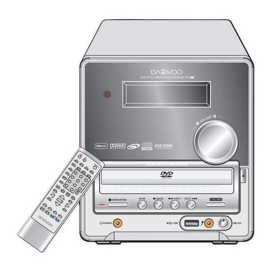
Location of Users Controls Front Panel 1. Remote Control Sensor 2. Display 3. DISC TRAY 4. STANDBY/ON ( ) button 5. STANDBY/ON LED lamp 6. PHONES jack 7. PLAY ( ) button 8. STOP ( ) button 9. PREV ( ) button 10. -
Page 7: Rear Panel
Location of Users Controls Rear Panel 1. FM ANTENNA connector 2. AM(MW) ANTENNA connector 3. SPEAKER connectors 4. SCART jack 5. COAXIAL OUTPUT jack 6. COMPONENT VIDEO OUTPUT Y/Cb,Pb/Cr,Pr jacks (Optional) 7. S-VIDEO MONITOR OUT jack 8. VIDEO OUTPUT jacks 9. -
Page 8: Remote Controller
Location of Users Controls Remote Controller (with DOLBY PROLOGIC II) 1. ON/STANDBY button 2. MUTE button 3. OPEN/CLOSE button POWER MUTE OPEN/CLOSE 4. PBC button 5. RETURN button RETURN STEP SLOW 6. STEP button 7. SLOW button DISPLAY P/I SCAN 8. -
Page 9: Connecting To Equipment
Connecting to Equipment Connecting to TV - 21-Pin SCART Cable(not included) to 21-pin SCART input terminal on TV - SCART Specification : Composite and Component Video output(DVD, Video)Audio L/R Output(DVD only) To Cr/Pr video input To Cb/Pb video input To Y video input for EU version: optional - If the TV or monitor is equipped with an S video input, make the S video connection in addition to the normal video connection. -
Page 10: Connecting The Supplied Fm/Am(Mw) Antennas
Connecting to Equipment Connecting the supplied FM/MW(AM) antennas(Option) Adjusting the position of the FM antenna While listening to an FM program, extend the antenna and move it in various directions until the clearest signal is received, then secure the antenna with push pins in the position with the least distortion. Adjusting the position of the AM(MW) antenna While listening to a AM(MW) program, set the antenna in the direction and position where you receive the clearest sound. -
Page 11: Firmware Upgrade
Firmware Upgrade Preparing the Firmware Upgrade 1. Write a disc to Update file by PC Writing Program. 2. A size of dummy folder is more than 10M bite. (ex : font_dw, attached picture) 3. Put Firmware file (DVDROM.BIN) in a disc. Activating the Firmware Upgrade 1. -
Page 12: Internal Block Diagram Of Ics
Internal Block Diagram of ICs 74HC4052 74L24 EL817 NJM4558M TL431... - Page 13 Internal Block Diagram of ICs CE2826 TDA8947 M29W800DB LD1117ADT-R...
- Page 14 Internal Block Diagram of ICs 24C04 AM5888 PT2579 OSC1 OSC2 DVDD 57kHz Oscillation Anti-Aliasing Reconstruction Quality Bit QUAL Band Pass & Filter Filter Generator (8th Order) Divider SCOUT Costas Loop Biphase Clocked Defferential Variable & Symbol RDDA Comparator Decoder Fixed Divider Decoder AVDD RDCL...
- Page 15 Internal Block Diagram of ICs SPHE8200A (with DOLBY PROLOGIC II) SPHE8200A...
-
Page 16: Exploded View And Mechanical Parts List
Exploded View and Mechanical Parts List... -
Page 17: Wiring Diagram
Wiring Diagram... -
Page 18: Block Diagram
Block Diagram... -
Page 19: Schematic Diagram
Schematic Diagram SMPS Section... - Page 20 Schematic Diagram POWER AMP Section...
- Page 21 Schematic Diagram EXTERNAL ADC Section...
- Page 22 Schematic Diagram AV SWITCH Section...
- Page 23 Schematic Diagram TUNER Section...
- Page 24 Schematic Diagram AUDIO FILTER Section...
- Page 25 Schematic Diagram VIDEO BUFFER Section...
- Page 26 Schematic Diagram MOTOR DRIVE Section...
- Page 27 Schematic Diagram RAM/FLASH/MEMORY Section...
- Page 28 Schematic Diagram DSP Section...
- Page 29 Schematic Diagram POWER Section...
- Page 30 Schematic Diagram FRONT Section 1...
- Page 31 Schematic Diagram FRONT Section 2...
-
Page 32: P.c.b Pattern Layout
P.C.B Pattern Layout MPEG <Top View>... - Page 33 P.C.B Pattern Layout MPEG <Bottom View>...
- Page 34 P.C.B Pattern Layout FRONT...
- Page 35 P.C.B Pattern Layout SMPS/AMP <Bottom View>...
-
Page 36: Electrical Parts List
APPENDIX - ELECTRICAL PART LIST... - Page 37 APPENDIX - ELECTRICAL PART LIST...
- Page 38 APPENDIX - ELECTRICAL PART LIST...
- Page 39 DAEWOO DAT CO., LTD.