Amprobe AM-510 User Manual
Commercial/residential multimeter
Hide thumbs
Also See for AM-510:
- User manual (146 pages) ,
- Replacement instructions manual (40 pages) ,
- User manual (290 pages)

Related Manuals for Amprobe AM-510


Summary of Contents for Amprobe AM-510
- Page 1 AM-510 Commercial / Residential Multimeter Users Manual 99 Washington Street Melrose, MA 02176 Phone 781-665-1400 Toll Free 1-800-517-8431 Visit us at www.TestEquipmentDepot.com...
-
Page 3: Commercial / Residential Multimeter
AM-510 Commercial / Residential Multimeter Users Manual July 2011, Rev.1 ©2011 Amprobe Test Tools. All rights reserved. Printed in China... - Page 4 Amprobe® Test Tools distributor for an exchange for the same or like product. Please check the “Where to Buy” section on www.amprobe. com for a list of distributors near you. Additionally, in the United States and Canada In-Warranty repair...
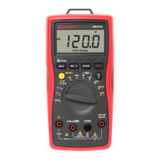
- Page 5 AM-510 Commercial / Residential Multimeter Flash light Flash light Button LCD Display Rotary Switch Function Buttons SELECT Button Input Terminal for voltage, frequency, diode, capacitance, resistance and continuity measurement COM (return) terminal for all measurements Input Terminal for battery test and AC/DC mA or μA...
- Page 6 Screen Display The Meter selects the range with best resolution Negative reading Alternate Current Low battery indicator Data hold Diode test Continuity test Relative zero mode Non-Contact Voltage Measurement units Duty Cycle Measurement unit for voltage Battery Test...
-
Page 7: Table Of Contents
AM-510 Commercial / Residential Multimeter CONTENTS SYMBOL .........................2 SAFETY INFORMATION ..................2 UNPACKING AND INSPECTION ................3 FEATURES .......................4 MAKING MEASUREMENT ..................5 Measuring AC and DC Voltage .................6 Measuring AC and DC Current .................7 Measuring Resistance ..................8 Measuring Continuity ..................9 Measuring Diode ....................9 Measuring Capacitance ..................10... -
Page 8: Symbol
SYMBOLS Caution ! Risk of electric shock. � Caution! Refer to the explanation in this Manual Alternating Current (AC) Direct Current (DC) The equipment is protected by double insulation or reinforced insulation Earth (Ground) Audible tone Battery � Complies with European Directives �... -
Page 9: Unpacking And Inspection
• Remove test leads from the Meter before opening the Meter case or battery door. UNPACKING AND INSPECTION Your shipping carton should include: AM-510 Multimeter Pair of test leads 9V (6F22) battery (installed) Users manual If any of the items are damaged or missing, return the complete package to... -
Page 10: Features
The AM-510 features a built-in flashlight to see wires in the dark, a kick stand, and probe holder to give you the “third-hand”... -
Page 11: Making Measurement
MAKING MEASUREMENT X� 1. Use the proper function and range for measurements. 2. To avoid possible electrical shock, personal injury or damages to the Meter, disconnect circuit power and discharge all high-voltage capacitors before testing resistance and diode. 3. Connecting test leads: •... -
Page 12: Measuring Ac And Dc Voltage
Display freezes present reading / press 2 sec to turn on HOLD / LCD backlight. Relative zero mode Manual or Auto range switching. The default setting is Auto ranging, press to switch to manual ranging RANGE (selectable resolutions). Press for 2 sec to return to auto ranging. -
Page 13: Measuring Ac And Dc Current
Measuring AC and DC Current Press SELECT button to select AC or DC current measurement function. X� To avoid personal injury or damage to the Meter: 1. Do not attempt to make an in-circuit current measurement when the open-circuit potential to earth ground exceeding 600V. 2. -
Page 14: Measuring Resistance
AC/DC Auto Range /Manual Range Measuring Resistance X� Disconnect circuit power and discharge all high-voltage capacitors before testing resistance. Note: On a higher resistance measurement (>1Me), the measurement may take a few seconds to get stable reading. Over range or open circuit indication: OL... -
Page 15: Measuring Continuity
Measuring Continuity X� Disconnect circuit power and discharge all high-voltage capacitors before testing continuity. R 1 0 Measuring Diode X� Disconnect circuit power and discharge all high-voltage capacitors before testing diode. -
Page 16: Measuring Capacitance
Measuring Capacitance X� Disconnect circuit power and discharge all high-voltage capacitors before testing capacitance. Auto Range Measuring Frequency Press Hz/% button to select Frequency / Duty Cycle measurement function. X� To avoid personal injury or damage to the Meter, do not apply voltage higher than 600V. -
Page 17: Non-Contact Voltage Sensing
Non-Contact Voltage Sensing X� 1. To avoid personal injury or damage to the Meter, do not test on un-insulated high voltage wires. 2. Buzzer will sound when detecting voltage higher than AC 90V. Screen displays“OL”. 3. Do not test on hazardous live wires higher than AC 600V. -
Page 18: Battery Test
Battery Test X� Applying a voltage source or incorrect battery type under battery test may cause personal injury or damage to the Meter. Battery 1.5V range is for dry battery not exceeding 2Vdc. The resistance load is around 30Ω. Battery 9V range is for dry battery not exceeding 15Vdc. The resistance load is around 1KΩ. - Page 19 Relative humidity: 0°C ~ +30°C (32°F ~ 86°F) ≤75%; +30°C ~ +40°C (86°F ~ 104°F) ≤50% Storage temperature: -10°C ~ +50°C (14°F ~ 122°F) Electromagnetic compatibility: In an RF filed of 1V/m = Specified accuracy ±5% Battery: 9V, 6F22, NEDA1604 or equivalent Low battery indication: Dimensions (L x W x H): 182 mm x 90 mm x 45 mm (7.2 in x 3.5 in x 1.8 in) Weight: Approx.
- Page 20 3. Resistance Measurement Range Resolution Accuracy 400.0Ω 0.1Ω ±(1.2%+2dgt) 4.000kΩ 1Ω 40.00kΩ 10Ω ±(1.0%+2dgt) 400.0kΩ 100Ω 4.000MΩ 1kΩ ±(1.2%+2dgt) 40.00MΩ 10kΩ ±(1.5%+5dgt) 400Ω range: Measured value = (Measured display value) – (Short-circuiting value of probe) Open circuit voltage: around 0.5V Overload protection: 600Vrms : Continuity G : Diode measurement...
- Page 21 6. Measurement of frequency/duty cycle Range Resolution Accuracy 10Hz~10MHz 0.01Hz~0. 01MHz ±(0.1%+4dgt) 0.1%~99.9% 0.1% Overload protection: 600Vrm Input amplitude: (DC level is 0.) 10Hz~1MHz: 300mV ≤ a ≤30Vrms >1MHz~10MHz: 600mV ≤ a ≤30Vrms Input amplitude and frequency response must meet following conditions when reading frequency or duty cycle during AC voltage or current measurement •...
- Page 22 Overload protection: � mA /μA input: F1 fuse, 0.5A H 600V fast-fuse, ( 6×32)mm 10 A input: F2 fuse, 10A H 600V fast-fuse, ( 6×32)mm 9. AC Current Measurement Range Resolution Accuracy 400.0μA 0.1μA μA 4000μA 1μA ±(1.2%+2dgt) 40.00mA 10μA 400.0mA 0.1mA 4.000A...
-
Page 23: Maintenance
MAINTENANCE AND REPAIR If the Meter fails to operate, check battery, test leads, etc., and replace as necessary. Double check the followings: 1. Replace the fuse or battery if the meter does not work. 2. Review the operating instructions for possible mistakes in operating procedure. -
Page 24: Battery And Fuse Replacement
Except for the replacement of the battery, repair of the meter should be performed only by a Factory Authorized Service Center or by other qualified instrument service personnel. The front panel and case can be cleaned with a mild solution of detergent and water.