Extron electronics SMP 351 User Manual
Streaming media processor
Hide thumbs
Also See for SMP 351:
- User manual (220 pages) ,
- Setup manual (11 pages) ,
- Application note (8 pages)

Related Manuals for Extron electronics SMP 351


Summary of Contents for Extron electronics SMP 351
- Page 1 User Guide Streaming AV Products SMP 351 Streaming Media Processor 68-2238-01 Rev. A 12 14...
-
Page 2: Safety Instructions
Safety Instructions Safety Instructions • English Инструкция по технике безопасности • Русский WARNING: This symbol, , when used on the product, is intended to ПРЕДУПРЕЖДЕНИЕ: Данный символ, , если указан alert the user of the presence of uninsulated dangerous voltage within the на... - Page 3 , and trademarks are the property of (SM) (TM) RGB Systems, Inc. or Extron Electronics: Registered Trademarks (®) AVTrac, Cable Cubby, CrossPoint, eBUS, EDID Manager, EDID Minder, Extron, Flat Field, GlobalViewer, Hideaway, Inline, IP Intercom, IP Link, Key Minder, LockIt, MediaLink, PlenumVault, PoleVault, PowerCage, Pure3, Quantum, SoundField, SpeedMount, SpeedSwitch, System INTEGRATOR, TeamWork, TouchLink, V-Lock, VersaTools, VN-Matrix, VoiceLift, WallVault, WindoWall, XTP, and XTP Systems...
- Page 4 Conventions Used in this Guide Notifications The following notifications are used in this guide: DANGER: • Will result in serious injury or death. • Entraînera des blessures graves ou la mort. Potential risk of severe injury or death. WARNING: AVERTISSEMENT : Risque potentiel de blessure grave ou de mort.
-
Page 5: Table Of Contents
Contents Comm Settings (View and Edit) Menu ... 41 Introduction ............ 1 Status Menu ..........42 About this Guide ..........1 Exit Menu ............. 42 About the SMP 351 ..........1 Front Panel Lockout (Executive Modes) .... 43 Suggested PC Requirements ......2 Alarms .............. - Page 6 File Management ..........122 Reference Information ....... 174 Disk Cleanup (Internal Storage Only) ... 123 Mounting the SMP 351 ........174 Expanding Folders to View File Lists ... 123 Tabletop Use ..........174 Finding Files ..........124 UL Rack Mounting Guidelines ..... 174 Upload a File to the SMP 351 ....
-
Page 7: Introduction
Introduction This section gives an overview of the user guide and describes the SMP 351 and its features. Topics that are covered include: • About this Guide • About the SMP 351 General Product Overview • • Features About this Guide This guide contains installation, configuration, and operating information for the SMP 351. In this guide: •... -
Page 8: Suggested Pc Requirements
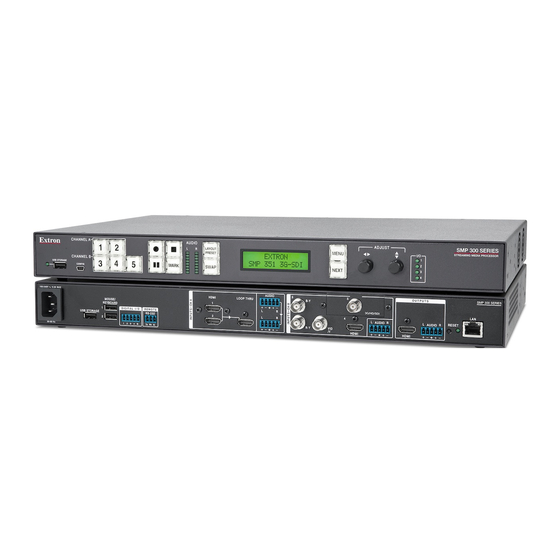
Extron SMP 351 Streaming Media Processor Extron CHANNEL A AUDIO ADJUST SMP 351 LAY O U T ME NU Streaming Media Processor P R E SE T CHANNEL B 3 4 5 USB STORAGE M ARK SWAP SWAP NE XT... -
Page 9: Licensed Third-Party Software
Licensed Third-party Software The following table lists the licensed third-party software used by the SMP 351. NOTE: Licensed third-party software used by the SMP 351 is subject to change without notice. Licensed Third-party Software Used in the SMP 351 Package License Package License ExtJS 4 Sencha Commercial License Linux-PAM... - Page 10 ifplugd GPLv2 psmisc GPLv2 iostat Artistic-2.0 jpeg-turbo jpeg-license (BSD-3c-like) python Python software foundation license v2, others kmod LGPLv2.1 qjson LGPLv2.1 libassuan LGPLv2.1 LGPLv2.1 with exceptions libcgicc LGPLv2.1 LGPL libcurl LGPLv2.1 libdaemon LGPLv2.1 smartmontools GPLv2 libdnet BSD-3c socat GPLv2 libelf LGPLv2+ spawn-fcgi BSD-3c libfcgi...
-
Page 11: General Product Overview
General Product Overview Input The SMP 351 can accept up to three HDMI inputs, one component or composite video input, and an optional 3G/HD/SDI input. The unit accepts digital audio embedded on HDMI signals or analog audio input via captive screw connectors. Inputs 1 (HDMI) and 2 (HDMI) are grouped as channel A. -
Page 12: File Storage
File Storage Internal storage is available for storing recordings and background image files. Two USB ports (one on the front panel, one on the rear panel) provide a connection for portable USB drives for storing recordings. Background image files can be imported from a network attached storage drive, if the unit is connected to a LAN (see Add a Network Share on page 127), but they must reside in... - Page 13 Make a recording The SMP 351 creates recordings by: • Scaling and arranging the content from one or both AV input channels (A and B) and the optional background .png file as defined by the selected layout preset (see Layout presets on page 94) •...
-
Page 14: Features
Features • Process two high resolution AV signals from up to five available inputs — Size and position two AV source signals in layouts that maximize the viewing experience. Stream and record simultaneously — Use the SMP 351 to document presentations •... - Page 15 Manage AV recordings using Extron Streaming Content Manager — SCM • prepares recording packages that offer an enhanced playback experience from the Extron Media Player (EMP). SCM manages users and groups, and transfers recording packages to a rights-managed storage directory. •...
- Page 16 Push and pull streaming session management — The flexibility to apply push and • pull streaming session management makes the SMP 351 compatible with a variety of H.264 devices and streaming applications. • Pull streaming transport protocols — RTP, RTSP interleaved, and HTTP tunneled streaming transport protocols may be applied, based on various network conditions or to aid in firewall navigation.
- Page 17 Picture controls for brightness, contrast, signal sampling, and overscan — 16 • user memory presets are available for each input to store all image settings. Aspect ratio control — The aspect ratio of a source window can be controlled by •...
-
Page 18: Panels And Cabling
Select a suitable mounting location (see Mounting the SMP 351 on page 174), then choose an appropriate mounting option. Make all external device connections before applying power. Rear Panel Overview SMP 351 100-240V --A MAX OUTPUTS AUDIO SMP 351... -
Page 19: Power Connection
Power Connection 100-240 VAC power input – Connect the provided IEC cord. Verify the front panel buttons and LCD illuminate (see Front Panel Features on page 18). Input Connections The audio and video inputs are grouped into channel A and channel B. Channel A analog audio input can be selected for video inputs 1 or 2 ( ). -
Page 20: Output Connections
Output Connections HDMI loop-thru output – Connect an HDMI (or DVI with suitable adapter) display device to the HDMI LOOP THRU connector to view the selected input 1 or input 2. Audio loop output – Connect a balanced or unbalanced stereo line level audio device to this 5-pole, 3.5 mm captive screw connector (see figure ). -
Page 21: Control System And External Device Connections
Control System and External Device Connections The SMP 351 can be configured and controlled from the Remote RS-232 port (see figure 3, on page 12) or the front panel USB mini-B Config port (see figure page 19) using SIS commands and DataViewer via telnet port 23, or from the LAN port using a standard Web browser. -
Page 22: Smp 351 Rear Panel Reset
Mode 1 RESET RESET Press and hold Apply power Release Reset button. the Reset button. to the SMP 351. Release, then immediately Modes 4 Reset LED flashes twice. press and release again. Reset LED flashes, then goes off. RESET RESET... - Page 23 Mode Activation Result Purpose and Notes Hold in the recessed rear The SMP 351 reverts to the factory Use mode 1 to revert to panel reset button while default firmware for a single power the factory default firmware applying power to the unit. cycle.
-
Page 24: Front Panel Operation
Layout Presets SMP 351 Power Up Procedure • • Front Panel Menu Operation Front Panel Lockout (Executive Modes) • Front Panel Features CHANNEL A SMP 351 AUDIO ADJUST LAYO UT MENU PRESENTATION CAPTURE RECORDER PR ES ET CHANNEL B 3 4 5... - Page 25 Record controls with LED indicators – Press the Record, Stop, Pause, and Mark buttons to perform the operation. The buttons light to indicate the current state of record operation. Record – Press to record the selected inputs. The record button lights solid red •...
-
Page 26: Layout Presets
Layout presets define which input or inputs are selected and where they are placed on the output screen. There are 12 preconfigured and 4 user presets for custom layout configurations. CHANNEL A AUDIO SMP 351 ADJUST LAYO U T ME NU PRESENTATION CAPTURE RECORDER... -
Page 27: Smp 351 Power Up Procedure
(and when the device is not being configured or has an active alarm), the default display cycle is on the LCD display. EXTRON EXTRON Power sec. ELECTRONICS SMP 351 FW V1.00 Default Display Cycle sec. In#1 1024x768@60 sec. ARCHIVE 2.0 MB... -
Page 28: Menu Overview
TIME REMAIN shows the time remaining for an active scheduled recording. EXTRON 351 FW V1.00 Default Display Cycle In#1 1024x768@60 ARCHIVE 2.0 MB sec. In#3 720p@60 1280x720@10 fps SMP 351 sec. ITIALIZING 2 sec. 2 sec. sec. TIME REMAIN TIME RECORD on shown in the default display cycle differs HH:MM:SS HH:MM:SS ctive input and the type of video signal. -
Page 29: Presets Menu
Presets Menu The presets menu allows the user to save or recall Encoder and User presets. From the default menu, press Menu to cycle to the Presets menu. Press Next to enter the submenus. Press Next to advance to the relevant submenu: Recall or Save. Within the submenu, use the Adjust controls to select the preset, then press Next to recall or save the selection. - Page 30 Default encoder presets The first nine encoder presets are predefined. Preset 3 is the default value for the Archive Encoder. Preset 9 is the default value for the Confidence Encoder. Preset Preset Resolution Video Frame Audio Bitrate H.264 H.264 Name Bitrate Rate Bitrate...
- Page 31 To save a user preset from the front panel: From the Picture Control menu, configure the selected input as desired (see Input Configuration Menu on page 33). Press Menu to cycle through the main menus to the Presets menu. Press Next to cycle to the User Save submenu. Rotate the left ( ) Adjust knob to select the input.
-
Page 32: Picture Control Menu
Picture Control Menu PICTURE Menu Menu CONTROL The Picture Control menu includes all picture settings like Color, Tint, Brightness, and Contrast of the picture. It allows the user to adjust horizontal and vertical window positioning along CHANNEL SELECT <A> ON with horizontal and vertical window size for the selected input Rotate either to select a (see... - Page 33 Picture size The Size submenu is used to set the horizontal and vertical size of the active video for the selected input. To use this submenu: • Rotate the left ( ) Adjust knob to change the horizontal size of the video for the selected input.
-
Page 34: Record And Stream Configuration Menu
Record and Stream Configuration Menu This menu allows the user to configure RECORD/STREAM the archive (recording) and confidence CONFIGURATION encodes. ENCODER ENCODER -OR- Use either Adjust knob to change the <ARCHIVE> <CONFIDENCE> Rotate either to Rotate either to selections. Press Next to enter changes select encoder type. - Page 35 Record To (archive only) The Record To submenu is available when the encoder selection is Archive and Encoder Mode is Recording On. This submenu allows you to define the drive the recorded video is stored to. It also displays the total drive space. NOTE: The SMP 351 can detect and record to USB storage devices using FAT32, VFAT long file name extensions, EXT2, EXT3, or EXT4 file systems.
- Page 36 Streaming Streaming is available in both Archive and Confidence encodes. Streaming can be ON (enabled) or OFF. When streaming is enabled, the STREAM METHOD, STREAM PROTOCOL, and MULTICAST or DESTINATION IP submenus are available. The appropriate submenus are displayed depending on the previous submenu selection. In the menus and submenus MULTI refers to a multicast protocol and UNI refers to unicast.
-
Page 37: Output Mode
Multicast IP for pull multicast When a multicast protocol is selected, the MULTICAST IP address must be entered. Check with the IT department for the correct multicast IP address for your network. Enter the MULTICAST IP address: Rotate the left ( ) Adjust knob to select the octet. - Page 38 Frame Rate (video) Archive and Confidence encodes have independent frame rate settings. This menu provides a frame rate selection (frames per second) from the following list: • 30 (default) • 12.5 • • • • • • Frame rates are selected separately for the Archive and Confidence encoder configurations. Bitrate (Video) Archive and Confidence encodes have independent video bitrate settings.
-
Page 39: Input Configuration Menu
Input Configuration Menu This menu allows the user to configure each of the five inputs. NOTE: The Input Configuration submenus are input specific. Depending on the input NOTE: The Input Configuration submenus are input type, not all submenus (shown in gray on subsequent pages) are available. specific. - Page 40 Next INPUT SELECT <1> Rotate either to select input. Signal sampling configuration INPUT #[3] <AUTO DETECT> Signal sampling optimizes the input signal for the currently selected input. The signal Rotate either to sampling settings are only available for analog inputs. select the input format.
-
Page 41: Aspect Ratio
Rotate to select the horizontal start pixel. Rotate to adjust the vertical start pixel. (3) H ACTIVE <1024> <0768> Rotate to adjust Horizontal Active pixel width. Rotate to adjust Vertical Active pixel height. Aspect Ratio (3) TTLPIX PHASE Aspect ratio can be selected per input. The selected input is displayed in the first line. <XXX>... - Page 42 <XXX> <16> Rotate to adjust TTL pixel width. Rotate to adjust phase. ASPECT RATIO IN[1] <FILL> Rotate either to EDID on HDMI connectors select an aspect ratio for the selected input. EDID emulation is available on HDMI inputs 1, 2 and 4. By default, all EDID INPUT #[1] three custom EDIDs are set to 720p @ 60 Hz, 2-channel audio.
-
Page 43: Background Recall Menu
Rotate to adjust phase. INPUT #[3] <AUTO DETECT> ASPECT RATIO IN[1] Rotate either to <FILL> select the input format. Rotate either to select an aspect ratio for the (3) H START selected input. <128> <128> Audio Select EDID INPUT #[1] Rotate to select the horizontal <720p_60_2ch>... -
Page 44: Advanced Configuration Menu
Advanced Configuration Menu The following flowchart provides an overview of the Advanced ADVANCED Menu Menu Configuration menu. Options include Auto-Image (on or CONFIG off), Auto Memory (on or off), HDMI preview out resolution, test patterns, record drive location limiter, device reboot, and factory IN<1>... -
Page 45: Test Patterns
IN<1> AUTO IMAGE <OFF> Rotate to select input. Rotate to toggle on or off. PREVIEW HDMI OUT <1280X720@60Hz> Auto Memory Rotate either to select a resolution. Auto Memory is enabled on all inputs by default. It should only be disabled if the user desires to have a source applied to the input AUTO MEMORY <ON>... - Page 46 <1280X720@60Hz> Rotate either to select a resolution. ADVANCED Menu Menu CONFIG AUTO MEMORY <ON> Rotate to toggle Auto IN<1> AUTO IMAGE Memory On or Off. <OFF> Universal OSD – This pattern consists of a small, • Rotate to select input. translucent, gray rectangle with white text overlaid atop Rotate to toggle on or off.
-
Page 47: Comm Settings (View And Edit) Menu
Comm Settings (View and Edit) Menu Press and hold VIEW COMM INPUT 5 + NEXT SETTINGS The two Comm Settings menus provide a status of the for 3 seconds. current serial port and IP settings for the communications ports. A hidden menu allows changes to the settings. “Hidden”... -
Page 48: Status Menu
Status Menu The STATUS menu contains read-only submenus that show the current unit status including active alarms, recording file names, free space EXIT MENU? and total internal and external drive capacity, and STATUS PRESS NEXT bitrates for archive and confidence streams. ALARM STATUS –... -
Page 49: Front Panel Lockout (Executive Modes)
Front Panel Lockout (Executive Modes) To prevent accidental changes to settings, press Menu and MARK simultaneously for 3 seconds to enable front panel lockout mode. The menu system returns to the default menu within 10 seconds. Executive mode begins in mode 1. Rotate either Adjust knob to cycle to mode 2, then mode 3, and mode 4 (Executive mode off). -
Page 50: Alarms
Alarms Alarms display a list of alerts for events as determined in the Web-UI (see Alarms page 134). The following table lists alarms generated by the SMP 351, what they mean, and how they are cleared. NOTE: All active alarms can be manually cleared by an administrator via the Web-UI. Alarm Alarm Generated Alarm Cleared... - Page 51 Alarm Alarm Generated Alarm Cleared NTP Sync Loss • If the SMP attempts to automatically The NTP Sync succeeds without retries for sync with the configured NTP server and a period of five synchronization attempts. fails the primary and retry attempts. If the SMP fails multiple manual sync •...
-
Page 52: Web-Based User Interface
Web-Based User Interface This section provides information about: Overview of the Web-Based User Interface • • Accessing the Web-Based User Interface • Page Overview Logging Out and Logging In • • AV Controls Panel Recording Controls • • Scheduled Events •... -
Page 53: Web Browser Requirements
Figure 18. SMP 351 Embedded Web Pages These Web pages provide the following features: • Ability to fully configure the SMP 351 • Ability to import a schedule or create ad hoc recordings Remote control and active monitoring of the SMP 351 • • A small embedded video window to view the AV content that is being recorded and streamed •... -
Page 54: Turning Off Compatibility Mode
Turning Off Compatibility Mode The SMP 351 embedded Web pages do not support compatibility mode in Microsoft Internet Explorer. To check compatibility view settings: From the browser, select Tools>Compatibility View Settings. The Compatibility View Settings dialog box opens. Be sure that the Display all Websites in Compatibility View check box is cleared and that the IP address of the SMP 351 is not in the list of Websites that are listed to the Compatibility view. -
Page 55: Pages Within Tabs
File Management — This page provides a way to view folders and files on the internal drive and any attached external drive, and to upload background image files to the unit. It also provides a way to connect the SMP 351 to shared network drives. Troubleshooting —... - Page 56 Collapse and expand panes Click the Expand ( ) arrow button on the right side of a pane to expand it. Click the Collapse ( ) arrow button at the top corner of a pane to collapse it. This hides the controls and provides additional room for other panes.
- Page 57 Web page idle (Timeout) To conserve resources (memory, bandwidth) on the PC, if the Web browser is idle for more than about an hour, the SMP 351 Web page enters idle mode. During idle mode, status updates and video confidence (preview) display image updates are suspended, and the following message is displayed in front of the page: Idle Communication with the device is being temporarily suspended to conserve...
-
Page 58: Logging Out And Logging In
Logging Out and Logging In To change roles (from administrator to user, or user to administrator) or user accounts, log out of the embedded Web pages. The user or administrator status is displayed in the upper right corner of all Web pages: The Logout button appears only if one or more passwords is active. - Page 59 Figure 26. Firefox Authentication Dialog Figure 27. Windows Authentication Dialog Enter the appropriate user or administrator user name and corresponding password into the fields. Click Log In or OK. The embedded Web page opens. SMP 351 • Web-Based User Interface...
-
Page 60: Av Controls Panel
AV Controls Panel The AV Controls panel is available on every page and within all tab views. Located along the left side of the pages, this panel makes it possible to easily control a recording, see a thumbnail view of the recorded and output video, swap video content between windows, select different inputs, and mute or unmute the AV output. -
Page 61: Input Selection
Progress bar A progress bar ( ) below the recording control buttons is a horizontal bar graph that shows how much recording time has elapsed and, if it is a scheduled session rather than an ad hoc recording, how long the presentation is expected to last. Recording time available Available recording time ( ) is indicated below the progress bar. -
Page 62: Start An Ad Hoc Recording
Start an Ad Hoc Recording A user logged on to the SMP 351 , either at the user (presenter) level or the administrator level, can initiate an ad hoc (unscheduled) recording. To start an ad hoc recording: In the AV Controls panel, select the desired active inputs (see AV Controls Panel page 54) for recording. - Page 63 Internal — The recording is saved in the internal memory of the SMP 351 . • usbfront/volume1, usbfront/volume2, usbfront/volume3, and so • on — The recording is stored to the selected external USB drive and volume (using whatever volume name is on that drive) connected to the front panel or rear panel USB storage port on the SMP 351 .
-
Page 64: Recording Controls
Recording Controls page displays information about the active inputs and the output Recording Controls signal, the presentation event currently in progress, and a list of upcoming presentations. Information on this page updates every few seconds. Contents of this page are read-only and are displayed for all users. -
Page 65: Stream Urls
Stream URLs This panel displays the URLs (addresses) for each encoded stream: Archive (recording) and Confidence (preview window). Figure 30. Recording Controls, Stream URLs Storage Information The storage information table below the Stream URL panel (also available in the File Management page) displays the names of the available connected storage devices, their locations (internal, USB front panel port, USB rear panel port), total capacity, and amount of used and available storage space. -
Page 66: System Inputs And Outputs
System Inputs and Outputs This panel displays information about the names, resolutions, refresh rates, HDCP status, and audio status for the two active inputs. It also displays the resolution, refresh rate, and HDCP status of the archive stream. Figure 32. Recording Controls, System Input and Output Information If the currently selected screen layout features the signal from only one channel at a time (such as the Fullscreen A or Fullscreen B layouts), a note is displayed on-screen that the... -
Page 67: Current Event
Current Event This panel displays information about the in-progress presentation. It includes: • Current date and time • Elapsed recording time Labels specific to the presentation content (name of the presenter, course name and • section, presentation title) — These labels are created during schedule setup or when an ad hoc recording (see Start an Ad Hoc Recording on page 56) is started via the... -
Page 68: Scheduled Events
Scheduled Events The Scheduled Events page lists all presentations (in-progress events, upcoming scheduled events, and presentations that have already taken place) in a calendar format. Events are listed by date and title. You can see a detailed view about each specific event from this page. -
Page 69: Re-Upload Files To A Server
The status of the recording, indicated near the bottom of the dialog, can include options such as: Recording Scheduled • Recording Now • Recording Finalized • Upload Failed to Start • Admin Requested Reupload • Uploading to Server • Upload Retries Failed •... -
Page 70: Configuration Overview
Configuration Overview The eight pages within the Configuration tab contain the core controls needed during initial setup or for upgrading the unit or restoring a configuration. They make it possible for a user logged in as an administrator to set up how to obtain presentation schedules, configure basic AV input settings, output video test patterns for setup, configure output stream settings and presets, set up AV encoding and presets, select or configure layouts and layout presets, set passwords, set up notices and alarms, select... -
Page 71: Schedule Settings
Schedule Settings The Schedule Settings page within Configuration allows a user with administrator privileges to choose how to obtain presentation schedules and, if appropriate, import calendars or connect to an Opencast Matterhorn scheduling system. Scheduling must be set up using this page. It cannot be set up via the front panel. To open this page, click the Configuration tab at the top of the SMP 351 embedded Web pages and then click the Schedule Settings tab on the second tier of tabs. - Page 72 iCalendar event schedule importing To import an iCalendar or .ics event schedule on a one-time basis: From the Schedule Settings page, select Manually import iCalendar one time. The Active Schedule Source dialog opens. Click OK to proceed. The Manual Calendar Import tab opens. Figure 40.
- Page 73 Import iCalendar schedules periodically To import iCalendar event schedules automatically from an FTP server on a recurring basis: From the Schedule Settings page, select the Import iCalendar data periodically radio button or click the Periodic Calendar Import tab. The Active Schedule Source dialog box opens. Click OK to proceed.
- Page 74 Scheduling with an opencast Matterhorn server To use an Opencast Matterhorn server to import event schedules automatically on an ongoing basis: Install and set up the Matterhorn server system. Write down the user name, server account password, and IP or DNS address of the Matterhorn system.
- Page 75 In the Capture Agent Name field, enter the SMP 351 unit name to appear on the Matterhorn server list of capture agents. By default, this is the same as the name of the SMP 351 as set up in the System Name field within the Unit Identification panel (see Setting the system (unit) name and location on page 107).
- Page 76 If desired, change the update or query intervals (in seconds) for the following items: Status URL — Determines how often the SMP 351 sends its current operations • status (capturing, uploading, idle, offline, and so on) to the Matterhorn server. Recording URL — Determines how often the SMP 351 sends the status of •...
-
Page 77: Input/Output Configuration
Input/Output Configuration The controls within the Input/Output Settings page within the Configuration tab provides a way to select a number of settings for video input and test the output and select options for audio output mode, mute, and levels. A user must be logged in as an administrator to see or change these settings. This page is divided into three panes: Input/Output Configuration –... -
Page 78: Configuring Inputs
Rows for currently selected inputs are highlighted in blue with a yellow bar on the left side. Except for input naming and HDCP authorization, all other controls and adjustments can be configured using the front panel menu and controls. Configuring inputs The Input Configuration panel of the page provides a way Input/Output Settings... - Page 79 Select (enable) or deselect (disable) the following check boxes for each input: Auto-Image — Select the check box to apply Auto-Image one time to the input. When selected, Auto-Image is applied whenever there is a change in the input sync. Auto-Image automatically sizes and centers the selected input.
- Page 80 HDMI preview output refresh rate To set the refresh rate for the local HDMI preview output: Open the Input/Output Settings page. Expand the Preview Output Configuration panel. Select the output refresh rate (either 50 Hz or 60 Hz) from the Refresh Rate drop-down list in the panel.
- Page 81 • The Pulse "test pattern" is an audio-only test. Select Pulse to output an audio pulse of 400 Hz at -10 dBu for audio output testing. The Time Stamp pattern displays white text in a small, translucent, gray rectangle with •...
- Page 82 OSD text appears on-screen in this format: Display Text, Information 1, Information 2, Information 3. Below are examples of how the configuration settings (on the left) translate to the universal OSD (on the right). REC1, 56% 00:10:33,20:10:51 OSD, SMP 351,1*4,up*100*full SMP 351 • Web-Based User Interface...
-
Page 83: Image Configuration
Image Configuration The controls within the Image Settings page within the Configuration tab provides a way to configure video input sampling and sizing, set up overscanning of SMPTE input signals, and adjust picture controls (brightness, contrast, and similar). This page also allows you to save or recall input and user presets. - Page 84 Except for the overscan settings and input preset saving and recalling, all settings on this page can also be configured using the front panel menu and controls. You must select an input from the Input Config panel in the upper left of this page before you can adjust the image settings or save or recall presets.
- Page 85 Positioning and sizing an image The Signal Sampling panel of the Image Settings page provides two options to size or crop and to set the location and aspect ratio of the currently selected input: Manual – Set each individual detailed parameter using direct entry or the Up and Down •...
- Page 86 Auto-Image & Fill— Fills the entire output window. Auto-Image & Follow — Maintains the aspect ratio of the input for the output video. NOTE: If overscan is applied, executing Auto-Image recalls default values for the detected resolution from an internal table. When overscan is set to 0%, Auto-Image attempts to detect sampling rates that differ from those in the table.
- Page 87 Input and user presets The Input Presets and User Presets panels within the Image Settings page saves the currently applied image settings for later use, or to recall and apply previously saved settings. NOTE: Input presets work when Auto Memory and Auto-Image are both off (disabled). See the table below for information stored in each preset type: Setting Input Presets...
-
Page 88: Input Presets
Input presets In this section of the Image Settings page, create up to 128 global input presets. These contain user-defined sets of input and picture control settings saved for each source within a system for recall whenever the source is selected. NOTE: An input preset can be recalled on any input supporting the input type that was active when the preset was saved. - Page 89 To recall an input preset: From the preset number list in the Input Presets panel, select the preset to recall. Click Recall Preset (located at the bottom of the same panel). A confirmation dialog box opens. In the dialog box, click Recall. NOTES: •...
- Page 90 To create and save a user preset: Select the applicable input (see Image Configuration on page 77). Adjusting picture controls Adjust the picture controls as desired (see on page 78). Select a preset number from the preset number list in the User Presets panel. In the Preset Name field, enter a name for the preset.
-
Page 91: Encoder Settings And Layout Presets Overview
Encoder Settings and Layout Presets Overview The controls within the Encoding & Layout page configure signal streaming and encoding and also permit selection or configuration of video layouts. A user must be logged in as an administrator to see or change these settings. To open this page, click the Configuration tab at the top of the SMP 351 embedded Web pages and then click the Encoding &... - Page 92 The first nine presets are populated with factory configurations which can be overwritten. Presets 10 through 16 are configured on the Encoding & Layout page. NOTE: Some of the parameters available on this page can also be set individually using front panel controls.
-
Page 93: Recall Preset
Recall encoding presets To recall an encoding preset: Click Configuration>Encoding & Layout at the top of the SMP 351 embedded Web pages. If it is not already expanded, click the down arrow to expand Encoding Presets In the panel, select (click on) a saved preset in the list and click Encoder Presets Recall Preset. - Page 94 Configure and save custom encoding presets Configure and save a user-defined encoding preset: Click the Configuration tab at the top of the SMP 351 embedded Web pages. Click the Encoding & Layout tab on the second tier of tabs. The Encoding & Layout page opens. Click the Expand arrow button ( ) to expand the Encoding Presets pane.
- Page 95 For recording (in the Archive Encoder column) select Audio + Video or Video Only from the Recording Enabled drop-down list and select an option from the Default Preset drop-down list. Configure video encoding (see Configure Video Encoding on page 89). Configure Video Encoding Configure audio encoding (see on page 89).
- Page 96 Select a frame rate (in Hz) from the Resolution drop-down list. Enter a number (from 1 to 30) into the GOP Length field or use the Up and Down arrows to change the value for the field to set a "group of pictures" (GOP) length. The default value is 30.
- Page 97 Configure audio encoding (in the Audio Encoding panel of the Archive Encoder column): Select the audio bit rate from the Audio Bitrate drop-down list. The SMP • supports rates of 80, 96, 128, 192, 256, and 320 bits per second (bps) for stereo audio.
- Page 98 Set the MTU (maximum transmission unit length in bytes), the maximum network packet size (in bytes) that the protocol and network layer can pass onward. Enter a number into the MTU: field or use the Up and Down arrows to change the value. The default is 1500 bytes.
- Page 99 Select the virtual port number for the stream by typing a number into the port# field or use the Up and Down arrows to change the value. The default port number is 6000. Set the MTU (maximum transmission unit length), the maximum network packet size (in bytes) that the protocol and network layer can pass onwards.
- Page 100 Layout presets NOTE: A user must be logged in as an administrator to see or change these settings. Layout presets define where on the screen the video windows for each input channel are located and how big each window is. Each channel (A and B) has a defined aspect ratio, size, and position.
- Page 101 Recalling Layout Presets To recall a layout preset: Open the Layout Presets pane. In the Layout Presets panel at the right of the page, select (click on) a saved preset in the list. The selection is highlighted. See the layout preset diagrams on the next page for the display appearance of each layout.
- Page 102 PBP Upp LFT — picture PBP Mid LFT — picture PIP Upp LFT — picture in (on behind (separate from) picture, behind (separate from) picture, top of) picture, channel B on channel B on upper left; mid-screen, channel B on left; upper left metadata at left metadata at left...
- Page 103 Click Recall Preset. A confirmation dialog box opens. Click Recall to recall the preset and immediately apply it to all of the streams (archive/recording and confidence/preview) or click Cancel to discard the change and use the previously selected layout. If desired, click the Launch Player button at the top of the Encoding & Layout page to open a stand-alone preview stream window.
- Page 104 Configure and save layout presets To configure and save a layout preset: Open the Layout Presets pane. ¢ ¢ Figure 57. Layout Presets In the Layout Presets panel ( ), select (click on) a saved preset in the list. Use the Select a Default Layout drop-down list ( ) to choose a factory default layout pattern to use for scheduled recordings.
- Page 105 Enter text in the field for Preset Name (which appears in the Layout Presets panel). Enter text in the fields for Summary and Description (which appear in various places within these embedded Web pages) to provide information about the selected layout preset.
- Page 106 In the Layout Presets panel, select (click on) an unassigned preset in the list and click Save Preset. The Preset Name field is now editable and changes from "[unassigned]" (left panel in the figure below) to "PIP PRESET ," (right panel in the figure below) the default name for that preset number.
- Page 107 If desired, enter the default text for each metadata type in the Default Value: field. For example, if the field type is META_PUBLISHER, the default text might be "Springfield University" or "XYZ Corporation." Default text for META_CONTRIBUTOR might be the name of a staff member whom regularly gives presentations from the room where the SMP is installed, such as "Dr.
-
Page 108: Users And Roles
Users and Roles In the page within Configuration, a user with administrator privileges Users and Roles can set up both administrator and user level passwords. Passwords are not required, though they are recommended for controlling access to configuration functions. An administrator password is required before a user password can be set. - Page 109 Enter the same password into the Confirm Password: field directly below the Administrator Password field. Once a password is entered, the fields in the Login ID: user panel are accessible. If no user password is set, click Save in the upper right of the Password panel. To set a user password, complete steps 4 through 6.
-
Page 110: Alarms And Traps
Alarms and Traps In the Alarms and Traps page within , a user with administrator privileges Configuration can configure e-mail account and communication settings to allow the unit to send notification e-mails. This is also the location for selecting whether to log, display a message about, or send an email about various conditions and errors experienced by the SMP 351 . -
Page 111: Configuring Alarms
Enter the address of the e-mail server into the Email Server Address: field. Select an encryption option from the Use Encryption drop-down list. None – Notification e-mails do not use encryption. • TLS – Notification e-mails are sent using TLS encryption. •... -
Page 112: System Settings
Alarm Priority Alarms and Troubleshooting Comments Traps Severity Log Severity Level Level High Notify Alert • Sends an e-mail to the specified recipient when the alarm is triggered • Displays the alert on the SMP 351 front panel. • Logs the alarm condition. Normal Display Notice... - Page 113 access to the controls and functions of the SMP 351. Click the Expand button on the top-right of the pane to expand it, or click the Collapse button to collapse it. Some of the settings can also be set using the front panel menu and controls or using SIS commands.
- Page 114 For all three options, access the Date and Time panel in the System Settings page by clicking the Expand button for the pane to expand it. The pane opens. To sync the unit with the connected computer: Click Sync Date and Time to PC. This sets the date, time, and time zone for the SMP 351 automatically based on the date and time of the connected computer.
- Page 115 Setting the IP address, port numbers, and other network settings In the Networking pane you set the IP addresses for the unit, gateway, and DNS server, as well as the subnet mask and port numbers for a variety of port types. To configure network settings: NOTE: Changes to any setting in this page are not applied and saved until you click Save.
- Page 116 If it will be used, configure SNMP. Simple Network Management Protocol (SNMP) facilitates the exchange of basic network management information between network devices. It helps in monitoring of operations and factors such as bandwidth, memory usage, remote password resets, and collection of error information. The text that is specified in the SNMP-related fields is seen by the network community when the unit is queried.
- Page 117 Signals from devices using link local IP addresses are not routed by routers and gateways. They stay within the local network. That makes it possible for many different LANs to use the same range of link local IP addresses without creating conflicts. Each LAN must use Network Address Translation (NAT) to hide private addresses and present only one or few public addresses to other or larger networks Set a default recording destination...
- Page 118 Type the address of the destination server into the Server Address: field. For FTP and SFTP servers, the server address must be given as the resolvable • address of the server itself (for example, ftp.extron.com/ or 10.1.25.41). This serves as the home level of the FTP server. It is an address that already exists on the server and that the SMP 351 has permission to access.
- Page 119 Enter the name of the primary operator of this SMP 351 unit into the User name: field. Enter the password for that user into the Password field. To display text instead of dots for the password, select (check) the Show Password check box. Enter a bit rate (in Kbps) in the Transfer Max Bitrate field, or use the Up and Down arrows to change the value.
- Page 120 The pane provides an example file name below the fields: Select either UTC Time or Local Time from the Date/Time Format drop-down list. Click Save to save the settings, click Reset to set the fields back to the factory default settings, or click Cancel to discard the changes.
-
Page 121: Updating Firmware
Updating firmware The Firmware Loader pane makes it possible to load new firmware to the unit. NOTE: Use a network connection (the LAN port) to upload firmware. Firmware uploads are not permitted via serial connections (rear panel RS-232 port or front or rear panel USB ports). - Page 122 Restore a Configuration To restore a configuration to the unit or to load a configuration saved from another SMP: In the System Settings page, click the Expand arrow button for the Backup and Restore pane to expand it. The pane opens. Click Browse.
-
Page 123: Live View Settings
Live View Settings In the Configuration>Live View Settings page, a user with administrator privileges can configure the media player settings for the Preview window in the AV Controls panel. These settings are available only via this page. They cannot be set via the front panel. Configure the Live Preview Player To configure the player and streaming method used in the Preview window: Click the Configuration tab at the top of the embedded Web pages and then click... -
Page 124: Advanced Features
Click Refresh now to refresh the embedded Web pages and apply the new settings to the Player window. The Live View dialog box closes and the Web page is refreshed. If the selected browser plugin is installed on the computer, the Preview window •... - Page 125 Connect a keyboard and mouse to control the SMP 351 You can set the SMP 351 to run a Web browser client application for direct control if a stand-alone computer is not available on site. If enabled, the internal Web browser provides access to a subset of the Network (IP) Settings configuration pane.
- Page 126 Open a Web browser and navigate to the SMP 351 product page at www.extron.com. Within the product page, click on the Downloads tab. In the Software listing section, locate the link for the desired plug-in and click on the link to start the download process. Complete the information form if requested to do so, then click Download and follow the on-screen instructions.
- Page 127 Close the plug-in window. You may be prompted to save changes before closing the window. Specify whether to run the application when the SMP 351 starts up or upon reboot. To do so: Click in the Startup State column of the Apps panel to access the drop-down list.
-
Page 128: File Management
File Management The File Management page contains a directory of files stored in the SMP 351 and also of any connected shared drives on the network, and a file upload utility so that new files can be added to the SMP 351 for use as background images. It also provides a way to connect the SMP 351 to shared network drives and lists the URL you can use to upload or download files from the SMP 351 through an SFTP client. -
Page 129: Disk Cleanup (Internal Storage Only)
Disk Cleanup (Internal Storage Only) Recording packages (folders and files within the /recordings/folder) cannot be deleted manually. If internal storage space is nearly full and the SMP 351 is set up to automatically upload recordings to a server (see Scheduling with an opencast Matterhorn server on page 68), then the disk cleanup feature makes room for new recordings. -
Page 130: Finding Files
Finding Files To find a file, do one of the following: • Expand folders in the File Directory panel (as described above) and browse through the file list. If desired, narrow the list of files to a specific type (such as images) by applying a filter to the directory. -
Page 131: Delete A File Or Folder
If desired, edit the text in the Destination Name: field. The destination name is the file name and extension, not a directory path. Perform one of the following: Enter the name of the directory folder in which the file will be stored into the •... -
Page 132: Create A New Folder
Create a New Folder If storage space is available, you can create a folder for storing background images or recordings. To create a folder: Click the File Management tab at the top of the SMP 351 embedded Web page. Right-click the folder or subfolder within which you want to create the new folder. A small dialog box opens. -
Page 133: Add A Network Share
To copy a file or folder from any folder shown in the list to any folder in the list: In the File Directory panel, click the adjacent to a folder to expand it if needed to locate the desired file or folder. Select one or more files or folders: click on a single item to select one file or folder, or <Shift>... - Page 134 For additional information on the network path format, options, and allowed characters, click the ? button in the upper right corner of the Network - Shares dialog, as shown below. User Name: and Password: — Entries in these fields are optional and used only if a •...
-
Page 135: Upload And Download Files Using An Sftp Client
Upload and Download Files Using an SFTP Client Set a default recording destination Automatic file uploading to a network location (see page 111 or Scheduling with an opencast Matterhorn server on page 68), the recording re-transfer (re-upload) option within the Scheduled Events page, and the option listed on the previous page for uploading background image files to the unit satisfy most file transfer needs. -
Page 136: Troubleshooting
Troubleshooting Troubleshooting Overview The five pages within the Troubleshooting tab contain controls typically used during initial setup to test connections and then later if a product support issue arises. They make it possible for a user logged in as an administrator to view current system conditions and connections, view event logs and alarms, test network connections, and reset the unit. -
Page 137: Status
Status The Status page within the Troubleshooting tab displays factory-defined and user-defined information about the unit. This page contains the unit name, part number, firmware version, MAC address, location description, and related information about the unit. It also displays the current audio bitrate and the video bitrates for all encoding streams. Some of the information in this page can also be found using SIS commands (see Command and Response Tables on page 155) or the front panel (see... - Page 138 filtered, searched, or exported to a comma-separated values (CSV) file. To open this page, click the Troubleshooting tab at the top of the embedded Web pages and then click the Logs tab on the second tier of tabs. The Logs page opens, showing filtering controls and the log list. Figure 65.
- Page 139 Filtering the logs The log list can be reduced to a subset of entries using filters. Select options within the panel. The changes take place immediately upon selection of the Filter the logs by: option. Multiple filters can be applied. To display entries for one particular recording event, select the desired event number from the Event ID drop-down list, or select Any to show all logs for all events.
-
Page 140: Alarms
Exporting the log list to a file To store a record of logged events as a file on a computer, click Export Log to CSV file. This creates a comma-delimited file of the log list and automatically downloads it to the default download folder on your computer. -
Page 141: Diagnostic Tools
Filtering the alarm list The alarms list can be reduced to a subset of entries using filters. Select options within the Filter the logs by: panel. Changes take place immediately upon selection of each option. Multiple filters can be applied at the same time. To filter the list by status, select an option from the Status drop-down list: •... - Page 142 Ping Test To test whether a particular device is connected to and communicating on a network, and how fast it is communicating, you can perform a ping test. This type of test sends an echo request ICMP packet to a designated IP address and "listens" for replies. Ping tests are used to determine whether a network share server is online, for example.
- Page 143 traceroute to 207.141.218.140 (207.141.218.140), 30 hops max, 38 byte packets 1 10.13.0.170 (10.13.0.170) 2.259 ms 1.487 ms 1.461 ms 2 cust-60.grnville.enet.net (210.90.168.98) 1.082 ms 0.775 ms 0.644 ms 3 * * * 4 * * * 5 * * * 6 * * * To retest the connection, click Trace.
- Page 144 To retest the connection click Nmap. To return to the Diagnostic Tools page, click Close. Generating and Retrieving a Log File If you need additional assistance troubleshooting an issue with the SMP 351 or with the network or system the SMP 351 is a part of, contact the Extron Technical Support Hotline. http://www.extron.com/company/contactus.aspx for the phone number for your regional office.
-
Page 145: System Resets
System Resets The System Resets page within Configuration allows you to initiate a unit reboot, delete all stored content and format the internal storage, or perform one of five different types of reset. Some of the reset options offered here can also be performed using SIS commands or the front panel menu. -
Page 146: Flex I/O Applications
Flex I/O Applications This section provides basic instructions on how to use each supplemental plug-in application (app) available for the SMP 351 . Topics include: • About the Digital I/O Configuration App • Access the Application When an app is downloaded and installed (see Advanced Features on page 118), a user must have administrator privileges to access the Advanced Features page and to use these... -
Page 147: Configuring And Labeling The Digital I/O Ports
The Advanced Features page opens to the Browser Client and Apps panes. Within the Apps pane, click the Configure button corresponding to the Digital I/O application in the Actions column. The application opens in a new window. Configuring and Labeling the Digital I/O Ports To configure the ports: Within the Apps panel of the Advanced Features page, click Configure in the row for the app named "Digital I/O". -
Page 148: Monitoring The Digital I/O Ports And Other Conditions
For example, "on" could be replaced by "press" or "start", and "off" could be replaced by "release" or "stop" if that port is connected to a pushbutton control. NOTE: The current state of each port is indicated by an LED icon in the Status column for your reference. - Page 149 To create monitors: From within the digital I/O configuration app, click the Monitor tab. You are prompted to either save (click Yes) or discard (click No) any changes made within the Config page. The Monitor page (shown below), allows you to select up to three specific conditions for the SMP 351 to monitor and up to three actions for the unit to take when the conditions occur.
- Page 150 By default, the SMP 351 monitors only the first condition (condition 1). To have the unit monitor conditions 2 or 3, select (check) the check box adjacent to each desired condition. If you set up condition 2 or condition 3 but decide not to monitor it, deselect the corresponding check box.
- Page 151 By default, the SMP 351 applies just the first action (action 1). To apply action 2 or 3, select (check) the check box adjacent to each desired action. Click Apply to save the configuration. NOTE: An error is returned if attempting to save a monitor without at least one condition and one action.
-
Page 152: Set The Startup State For The Application
Set the Startup State for the Application If desired, specify whether to run the application when the SMP starts up or upon reboot. You must do this within the SMP 351 embedded Web pages, in the Configuration > Advanced Features > Apps panel, not within the application. To do so: Click in the Startup State column of the Apps panel to access the drop-down list. -
Page 153: Remote Communication And Control
Remote Communication and Control This section describes SIS programming and control of the SMP 351, including: • Connection Options Host-to-device Communications • • Command and Response Tables Connection Options The SMP 351 Streaming Media Processor can be remotely connected via a host computer or other device (such as a control system) to the rear panel RS-232 port or LAN port, or the front panel USB Config port. -
Page 154: Front Panel Configuration Port
Front Panel Configuration Port The mini type B USB port is located on the front panel (see Front Panel Features page 18). It connects to a host computer for configuration using SIS commands with DataViewer, available at www.extron.com. To connect the SMP 351 to a host computer: NOTE: If an Extron USB device has never been connected to the host computer, prior to connecting the SMP 351 config (USB) port for the first time, you must install and activate the USB driver. -
Page 155: Ethernet (Lan) Port
Click Next. The PC locates the driver and installs it. When the Completed dialog opens, click Finish to close the wizard. NOTE: The wizard opens only on the first occasion you connect the SMP 351 to a USB port. The wizard reopens only if you connect the SMP 351 to a different USB port or if you connect a different piece of equipment, requiring a different driver, to the same USB port. -
Page 156: Verbose Mode
The SMP 351-initiated messages are listed here (underlined). © Copyright 2014, Extron Electronics, SMP 351, Vn.nn, 60– 1324-01 Day, DD MMM YYYY HH:MM:SS © Copyright 2014, Extron Electronics, SMP 351 3G-SDI, Vn.nn, 60– 1324-02 Day, DD MMM YYYY HH:MM:SS is the firmware version number. -
Page 157: Password Information
The SMP 351 sends the copyright messages under the following circumstances: • If the SMP 351 is off and an RS-232 connection is already set up (the PC is cabled to the SMP 351 and a serial communication program such as HyperTerminal is open), the connected unit sends these messages via RS-232 when first powered on. -
Page 158: Symbol Definitions
Symbol definitions = Encode profile = CR/LF (carriage return/line feed) 1=base or ¦ = Carriage return (no line feed, hex 0D) 2=main • = Space 3=high or W = Escape = Output mode 1=video and audio 2=video only Assigned or unassigned disabled or unassigned = Bitrate control type 0=VBR... - Page 159 X6& X51$ = EDID User location (1, 2, and 3) = Input name, up to 16 characters (default: "Input " where " " is the input = EDID resolution (see Table 1 number) page 169) X53) = User/Encoder/Layout Preset number = Port timeout in tens of seconds (zero (1 to 16) padded.
- Page 160 X56% = Test patterns (0 to 8) 0= Off (default) 1= Color bars 2= Aspect ratio 1.33 3= Aspect ratio 1.78 4= Aspect ratio 1.85 5= Crop 6= Pulse 7= Timestamp 8= Universal OSD X58! = Front panel audio level indication -1500 to 0 full bars =0, no bars = <-600...
-
Page 161: Command And Response Tables
Command and Response Tables SIS Command Response Additonal Description Command Function (Host to Device) (Device to Host) Information requests An asterisk (*) after the version number indicates the currently running version. Question marks (?.??) indicate that only NOTE: factory firmware is loaded. A caret (^) indicates the firmware version that should be running, but a Mode 1 reset (see SMP 351 Rear Panel Reset on page 16) was executed and the default factory firmware is running. -
Page 162: System Commands
Command and Response Tables (continued) SIS Command Response Additonal Description Command Function (Host to Device) (Device to Host) Set unit name E X1@ X1@ ] X10) ] Set unit name to • CN default View unit name X1@ ] View telnet n=number of active IP connections connections. - Page 163 Command and Response Tables (continued) SIS Command Response Additional Command Description (host to unit) (unit to host) Port Assignment NOTES: • Duplicate assignments are not permitted (for example, the telnet and Web port assignment cannot port# be the same) and will return the error.
- Page 164 ASCII Command Response Additional Command Description (host to unit) (unit to host) SNMP (Simple Network Management Protocol) SNMP unit contact Set unit contact X62! * X62!] Sets the unit contact SNMP SnmpC X62! Set unit contact to • Sets the unit contact to the SNMP SnmpC*Not•Specified default...
- Page 165 Command and Response Tables (continued) SIS Command Response Additional Command (host to unit) (unit to host) Description IP Setup Commands Set date / time X1# ] Set the date and time. MM/DD/YY- Ipt • HH:MM:SS CT X1# ] View date / time View the date and time.
- Page 166 Command and Response Tables (continued) SIS Command Response Additional Command (host to unit) (unit to host) Description RS-232 Port • X2& X2*] Configure serial port X2& Cpn 1 parameters • X2& X2*] Reset serial port 1*9600,n,8,1CP Cpn 1 X2& X2* ] View serial port settings NOTES:...
- Page 167 Command and Response Tables (continued) ASCtII command Response Additional description Command (host to device) (device to host) Password and Security Settings Set administrator E X3# • X3#] = Up to 12 alpha-numeric password characters View administrator If no password is set, the **** password ****...
-
Page 168: Input Configuration
Command and Response Tables (continued) ASCII Command Response Additional Command (host to unit) (unit to host) Description Input Selection Select input X50! * X50@ ! X50! * X50@] X50! Switches input X50@ channel View selected X50@ ! X50!] X50! View the input source input X50@ for channel... - Page 169 Command and Response Tables (continued) ASCII Command Response Command Additional Description (host to unit) (unit to host) Recording Stop recording Y0 RCDR RcdrY0 Start recording Y1 RCDR RcdrY1 Pause recording Y2 RCDR RcdrY2 X54)] View record status Y RCDR X54! X54! ] Extend record time For scheduled recordings only,...
- Page 170 Command and Response Tables (continued) ASCII Command Response Additional Command (host to unit) (unit to host) Description User Presets Recall user preset 1* X50@ * X53) . X50@ X53)] X50@ 1Rpr Recall channel preset X53) number Save user preset 1* X50@ * X53) , X50@ X53)] 1Spr...
- Page 171 Command and Response Tables (continued) Command ASCII Command Response Description (host to unit) (unit to host) Input adjustments (Input 3 only) Pixel Phase X60# Set pixel phase * X60# * X60#] PHAS Phas 3 Set input to pixel phase Increment pixel * X60#] PHAS Phas 3...
- Page 172 Command and Response Tables (continued) Command ASCII Command Response Description (host to unit) (unit to host) Active Pixels Set active pixels * X60& * X60&] Set the active pixels per line for input APIX Apix 3 X60& 3 to Increment active * X60&] X60&...
- Page 173 Command and Response Tables (continued) ASCII Command Response Additional Command (host to unit) (unit to host) Description Picture adjustments Color (NTSC and PAL inputs only) X50@ X60*] X60* Specify a value E X50@ * X60* COLR Colr Sets color level to Increment value E X50@ X50@ * X60* ]...
- Page 174 Command and Response Tables (continued) ASCII Command Response Additional Command (host to unit) (unit to host) Description Vertical Centering E 1* X50@ * X61! X50@ * X61! ] X61! Specify a value VCTR Vctr Set vertical centering to E 1* X50@ X50@ * X61! ] Increment value Shift window down.
- Page 175 Table 1. EDID Values Resolution Refresh Rate Type Video Format Audio 800 x 600 60 Hz 1024 x 768 60 Hz 1280 x 720 60 Hz 1280 x 768 60 Hz 1280 x 800 60 Hz 1280 x 1024 60 Hz 1360 x 768 60 Hz 1366 x 768...
- Page 176 Command and Response Tables (continued) ASCII Command Response Additional Command (host to unit) (unit to host) Description Encoder Settings (Archive Encode and Recording) Encoder profile X4) ] Set profile E 1* X4) EPRO Epro Set encode profile to View profile X4) ] EPRO View encode profile...
- Page 177 ASCII Command Response Additional Command (host to unit) (unit to host) Description Record resolution and frame rate X4^ ] Set record VRES Vres1* Set record resolution to resolution View record X4^ ] 1 VRES resolution X4& X4& ] Set record frame Set record frame rate to VFRM Vfrm1*...
-
Page 178: Advanced Configuration
ASCII Command Response Additional Command (host to unit) (unit to host) Description Advanced Configuration Overscan mode Set overscan E X50$ * X51) X50$ * X51)] X50$ OSCN Oscn Sets input type mode X51) overscan mode E X50$ X51)] View overscan View the current overscan OSCN mode... - Page 179 ASCII Command Response Additional Command (host to unit) (unit to host) Description Audio Audio delay NOTE: Set the audio delay to zero to disable it. Set audio delay E 1 X56$ * X56$ ] Set audio delay (0 to 999 ADLY Adly1 msec).
-
Page 180: Reference Information
Reference Information This section provides information about: Mounting the SMP 351 • • Supported File Types, Drive Formats, Browsers, and Browser Plugins Dataviewer • • Glossary Mounting the SMP 351 The 1U high, full rack width, 11.5 inch deep SMP 351 Streaming Media Decoder can be: •... -
Page 181: Rack Mounting
Rack Mounting For rack mounting using the included rack mounts, do not install the rubber feet. Mount the SMP 351 on a 19 inch universal or basic rack shelf. Furniture Mounting Furniture mount the SMP 351 using an optional under-desk or through-desk mounting kit. Follow the instructions included with the mounting kit. -
Page 182: Supported File Types, Drive Formats, Browsers, And Browser Plugins
Supported File Types, Drive Formats, Browsers, and Browser Plugins File Formats The SMP 351 creates *.m4v video and audio files. It uses still image files for background material. Video File Types • mp4 (including mp4, m4v) Still Image File Types • png (for background images) •... -
Page 183: Dataviewer
Dataviewer DataViewer is an enhanced terminal emulation program that facilitates analysis of RS-232, USB, and TCP/IP communication with Extron devices. The software allows users to send commands to a device and view the responses in ASCII or hexadecimal format. Command and response logs can be saved in text or HTML format. - Page 184 For example, enter 1I, the command to display the model name, in the Commands: field on the left side. The Responses: field on the right returns the model number of the connected device. Enter SIS View Commands Responses SMP 351 Figure 74. Enter Commands and View Responses SMP 351 • Reference Information...
-
Page 185: Ip Addressing
IP Addressing What is an IP Address? A full explanation of IP addressing is beyond the scope of this user guide. However, the following information is enough to get started. An IP address is a 32-bit binary number that is used to identify each device on an Ethernet network. -
Page 186: Subnet Mask
Subnet Mask The subnet mask is a 32-bit binary number used to "mask" certain bits of the IP address. It extends the number of network options available for the IP address. The subnet mask does this by allowing part of the host identifier to be used as a subnetwork identifier. It is important that the correct value is used for the subnet mask. -
Page 187: Using The Ping Utility To Test Communications
The table below shows an example of a valid class C addressing scheme. Device IP Address Subnet Mask Device 1 208.132.180.41 255.255.255.0 Device 2 208.132.180.42 255.255.255.0 Device 3 208.132.180.43 255.255.255.0 NOTE: The host identifiers ( , and in the example above) do not need to be in sequential or in any particular order. -
Page 188: Multicast Ip Addressing For Multiple Smp 351 Installations
— The IP address • Reply from 208.132.180.48: Destination host unreachable of the computer is not in the same class as the device being pinged. Check that the subnet mask on both the computer and the device are set to the same value. Also check that both IP addresses are within the correct range for the chosen class and are compatible. -
Page 189: Streaming Method Overview
SMP 351 waits for viewing devices to request the stream before broadcasting. Streaming Streaming Protocol Protocol Viewing SMP 351 NETWORK device (encoder) SMP 351 sends data Streaming Protocol Viewing to a multicast group. device Streaming Protocol Viewing device Streaming... -
Page 190: Unicast Streaming Method - An Overview
SMP 351 waits for an individual viewing device to request the stream before broadcasting. 1 to n Device 1 Viewing SMP 351 NETWORK device (encoder) SMP 351 sends data to Device 2 Viewing specified devices. device Device 3 Viewing device Device n... -
Page 191: Streaming Playback Methods
(pull streaming). Push Streaming Viewers select an active stream from SMP 351. Stream Stream Viewing SMP 351... -
Page 192: Push And Pull Stream Playback Urls
Push and Pull Stream Playback URLs To verify a running stream, use the templates below to place the stream into the VLC "Open Network Stream" dialog (see step 5 of Playing a Pull Stream Using VLC Media Player on page 189). Substitute the SMP 351 IP address for <SMP351_IP>. -
Page 193: Streaming Capabilities And System Scalability
Streaming Capabilities and System Scalability The following tables detail the streaming capabilities of the SMP 351. Data for the tables was obtained through laboratory testing using optimal bandwidth conditions and can vary depending on the selected video bit rate. NOTE: Testing to determine the approximate maximum number of pull streams was done on the Archive encode with one pull unicast confidence stream. -
Page 194: Available Multicast Streams
Available Multicast Streams The SMP 351 uses the IGMP multicast protocol to push or pull streams. The IGMP multicast protocol provides increased bandwidth efficiency because the SMP 351 only sends data when a connection is made by the user. All network switches and routing equipment must be properly configured to support IGMP snooping and IGMP query to avoid flooding all endpoints with unnecessary streaming traffic. -
Page 195: Playing A Pull Stream Using Vlc Media Player
Playing a Pull Stream Using VLC Media Player Use the following procedure to play and view an SMP 351 stream using the VLC media player. If you know the stream URL, go to step 5. Otherwise, to obtain the stream URL, access the Web-based user interface of the SMP 351 (see Accessing the Web-Based User Interface on page 48). - Page 196 The Open Network Media dialog box opens. Enter the stream URL that was noted in step 2 (see figure 79 on the previous page) in the field Please enter a network URL: rtsp://10.13.168.131/extron1 Figure 80. Enter Stream URL Information and Play Click ).
-
Page 197: Playing A Push Stream Using Stream Announcement Protocol (Sap)
Playing a Push Stream Using Stream Announcement Protocol (SAP) In order to play a push stream, the VLC player uses SAP to identify streams: Open VLC. From the View menu, select Playlist (see figure 81). Figure 81. VLC Playlist From the left menu column, select Local Network, then select Network streams (SAP) (see figure 82). - Page 198 VLC populates the playlist with all streams that contain SAP information. If a folder is shown, open it to view the SAP streams inside (see figure 83). SMP-351-HD-07-AD-EC-IGS SMP-351-SD-08-57-AA Stream Figure 83. VLC - Select a Stream Either double-click the desired stream to begin playback, or single-click, then use the VLC player controls at the bottom of the window to view and control the stream.
-
Page 199: Playing A Stream Using Quicktime Media Player
Playing a Stream Using QuickTime Media Player Use the following procedure to playback and view SMP 351 streams on the QuickTime player program. If you know the stream URL, go to step 4. Otherwise, to obtain the stream URL, access the Web-based user interface of the SMP 351 (see Accessing the Web-Based User Interface on page 48). - Page 200 The Open URL dialog opens. In the Enter an Internet URL to open: field, enter the stream URL that was noted in step 3 of this procedure (see figure 84 on the previous page). Enter an Internet URL to open: rtsp://10.13.168.131/extron1 Figure 86.
-
Page 201: Front Panel Menu Diagrams
SMP 351 • Reference Information... -
Page 202: Front Panel Menu Diagrams (Record/Stream Configuration)
SMP 351 • Reference Information... -
Page 203: Glossary
Glossary Ad hoc recording — An ad hoc recording session is one that has been set up for a specific occasion or task without being previously scheduled. Advanced Audio Coding (AAC) — A standardized compression and encoding scheme for lossy (low quality) digital audio. Higher bit rates provide higher quality. Part of the MPEG-2 and MPEG-4 specifications. - Page 204 DDC — Display Data Channel (DDC) is a bi-directional communications standard developed by VESA (Video Electronics Standards Association) that defines a universal data transmission standard for the connectivity between display devices and computers. Decoder — A hardware device or software program used to decompress (decode) or change a signal from one format to another or convert a digital signal into analog.
- Page 205 HDCP — High-bandwidth Digital Content Protection. HDCP is a digital rights management scheme developed by Intel to prevent the copying of digital video and audio content. ® HDCP is mandatory for the HDMI interface, optional for DVI. HDCP defines three basic system components: source, sink, and repeater.
- Page 206 JavaScript — A scripting programming language adding interactive features to Web ® pages. LAN — Local Area Network. A computer network that connects devices in a limited area, such as a building or campus, using network equipment that does not include leased communications lines.
- Page 207 Push streaming — A streaming method where the encoder sends content out to one (unicast) or more (multicast) decoders using one of the transport protocols. Content streaming is initiated at the encoder. Quality of Service (QoS) — The grade of performance, such as transmission rates and error rates, of a communications channel or system.
- Page 208 Switch — A network switch enables communication between devices in a network by routing data between ports at the data link layer (layer 2 of the OSI model). A managed switch can be configured to transmit data only to the specific device for which the data was meant.
-
Page 209: Extron Warranty
Extron Electronics makes no further warranties either expressed or implied with respect to the product and its quality, performance, merchantability, or fitness for any particular use. In no event will Extron Electronics be liable for direct, indirect, or consequential damages resulting from any defect in this product even if Extron Electronics has been advised of such damage.