Lexicon PCM 80 User Manual
Lexicon user guide digital effects processor pcm 80
Hide thumbs
Also See for PCM 80:
- User manual (17 pages) ,
- Presets (4 pages) ,
- Quick reference manual (2 pages)
Table of Contents
Advertisement
Quick Links
Advertisement
Table of Contents

Related Manuals for Lexicon PCM 80


Summary of Contents for Lexicon PCM 80
- Page 1 PCM 80 Digital Effects Processor User Guide...
-
Page 2: Unpacking And Inspection
Unpacking and Inspection After unpacking the PCM 80, save all packing materials in case you ever need to ship the unit. Thoroughly inspect the PCM 80 and packing materials for signs of damage. Report any shipment damage to the carrier at once; report equipment malfunction to your dealer. - Page 3 PCM 80 Digital Effects Processor User Guide...
- Page 4 Dansk Vigtig information om sikkerhed Gem denne vejledning til senere brug. Følg alle anvisninger og advarsler på apparatet. Apparatet skal altid tilsluttes den korrekte spænding. Der henvises til brugsanvisningen, der indeholder specifikationer for strømforsyning. Der gøres opmærksom på, at ved varierende driftsspændinger kan det blive nødvendigt at bruge andre lednings- og/eller stiktyper.
- Page 5 Deutsch Wichtige Sicherheitsanweisungen Heben Sie sich diese Sicherheitsanweisungen auch für später auf. Befolgen Sie alle auf der Vorrichtung stehenden Anweisungen und Warnungen. Immer nur mit der richtigen Spannung verwenden! Die Gebrauchsanweisungen des Herstellers informieren Sie über die elektrischen Anforderungen. Vergessen Sie nicht daß bei verschiedenen Betriebsspannungen ggf. auch verschiedene Leitungskabel und/oder Verbindungsstecker zu verwenden sind.
-
Page 6: Table Of Contents
Introduction 1. Product Overview Block Diagram ... 1-1 Front Panel Overview ... 1-2 Rear Panel Overview ... 1-3 Installation Notes ... 1-4 Mounting ... 1-4 Power Requirements ... 1-4 Audio Connections ... 1-4 Control Connections ... 1-4 Setting Audio Levels ... 1-5 Headroom Display •... - Page 7 Contents, cont'd. 3. The Algorithms and their Parameters About the Algorithms ... 3-1 The 4-Voice Algorithms ... 3-2 The 6-Voice Algorithms ... 3-8 The Parameters ... 3-16 4. The Presets Program Bank 0 ... 4-2 Program Bank 1 ... 4-6 Program Bank 2 ...
- Page 8 Selecting a MIDI Channel ... 5-1 Controlling PCM 80 Tempo Rate with MIDI Clock ... 5-2 MIDI Tempo Control • Using the PCM 80 as a MIDI Control Source • Slaving two or more PCM 80s Controller Quirks ... 5-4 The ADJUST Knob, Foot Pedal, Foot Sw 1 and Foot Sw 2 as MIDI controllers ...
-
Page 9: Introduction
Thank you for your purchase of the PCM 80, one of Lexicon’s most powerful and versatile digital effects processors. The PCM 80 brings you exciting new effects with extensive processing and control capabilities, and uncompromising sonic clarity. The PCM 80 contains a built-in library of 200 preset programs that provide a comprehensive array of effects ranging from beautiful and lush to completely wild. - Page 10 To get the most out of the PCM 80, we suggest that you invest the time to explore this manual. We think you’ll agree that the time spent investigating will reward...
-
Page 11: Product Overview
Product Overview Product Overview Block Diagram... -
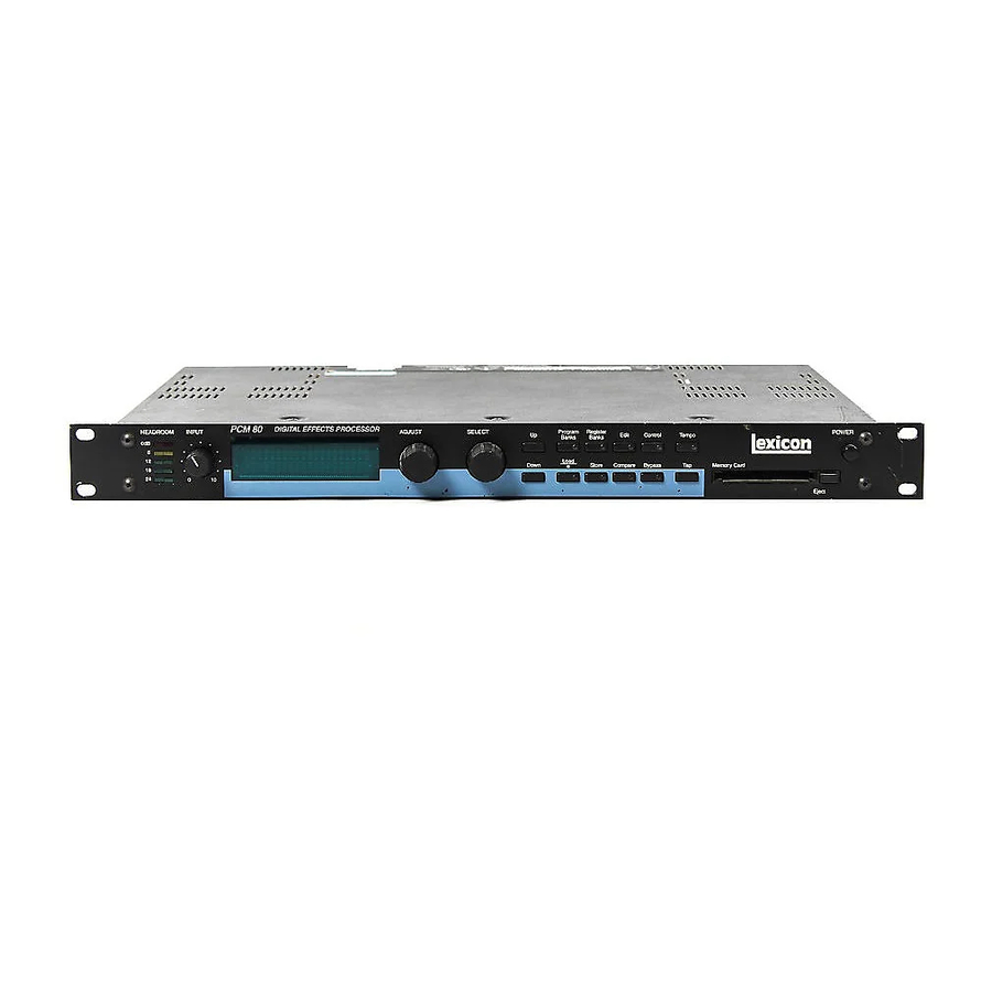
Page 12: The Front Panel
PCM 80 User Guide The Front Panel Headroom 5-position indicator for analog and digital sig- Display nal levels and over- Two rows of 20 alpha- load conditions. numeric characters display effect names INPUT and ID numbers, and parameter names and Adjusts analog input values. -
Page 13: The Rear Panel
S/PDIF S/PDIF format digital connectors conform to CP-340 Type II and IEC-958 consumer standards. AC Power MIDI Standard 3-pin IEC power connector. 100- Receives MIDI infor- 240V, 50-60Hz auto- mation from other matic switching to cor- MIDI equipment such rect voltage range. as master keyboard controllers, MIDI foot controllers, sequen-... -
Page 14: Installation Notes
The PCM 80 uses one EIA-standard rack space, and can be mounted on any level surface or in a standard 19 inch (483 mm) rack. If the PCM 80 is mounted in a rack or road case, support the rear of the chassis to prevent possible damage from mechanical shock and vibration. -
Page 15: Setting Audio Levels
The PCM 80, with both analog and digital input and output connections, requires some attention to proper setting of signal level. Analog inputs are first gain-conditioned by the rear panel input gain switch, and then by the front panel INPUT knob. Proper setting of both the switch and knob are important for best performance of the A/D converter. - Page 16 NOTE: If you are not running digital audio, controlled by External Clock, into the PCM 80, the digital audio input will be disabled or muted. Until there is valid digital audio input, select 0.0 External to enable the digital input level control.
-
Page 17: Configurations
If you will be using a PCM 80 as your primary effects unit, and your system includes a console with one or more auxiliary (effects) sends, connect the PCM 80 as shown above. In most applications, it is preferable to connect the PCM 80 outputs to two of the console's input channel strips, panned full left and right, rather than to the effects returns. -
Page 18: Memory Cards
Memory cards can also be used to store "setups" (your system configuration, as set in Control mode). As many as 5 PCM 80 setups can be stored on a card, allowing you to transport not only your effects, but complete PCM 80 environ- ments to another PCM 80. -
Page 19: Basic Operation
Press Tempo to set tempo-related values that affect the delay time and LFO rate parameters of the currently-running effect. This is an exciting feature which is unique to the PCM 80, and which will be described in detail later in this chapter. -
Page 20: Navigating A Matrix
In the other modes, ADJUST scrolls through the range of available settings for the control you have selected. The PCM 80 offers a choice between two levels of Edit mode parameter access. We call these Go mode and Pro mode. -
Page 21: Info
The PCM 80 offers an extensive set of informative display messages which can be activated from the front panel. The front panel switches perform various functions when pressed. Most of these functions are activated on release of the button. If you want to know more about the function of a particular button (without actually executing any action) press and hold the button down. -
Page 22: Control Mode
0.0 Word Clock The PCM 80 can use its own internal clock as a timing reference, or it can reference an external clock source from the rear panel S/PDIF jack. Use ADJUST to select Ext (External), Int: 48kHz or Int: 44.1kHz. When either Internal rate is selected, the digital input is disabled. -
Page 23: Error Log
Audio *Dig In Status 0.0 Prf 44.1 Emp:Yes When the PCM 80 loses lock, it will mute the digital input and switch to Internal Clock. Error Log The following errors are continuously logged and are available for review by pressing Load/ from the Dig In Status display and using ADJUST to scroll through the error list. - Page 24 Values between 0% and 100% are for mixing analog and digital sources. Note: If the analog signal being fed into the PCM 80 is too hot, turn it down by adjusting the front panel INPUT level control, or by changing the rear panel Input Gain switch.
- Page 25 0.3 Auto Lock When Word Clock is set to Ext, and the PCM 80 loses lock with an incoming digital audio signal, it will immediately switch to Internal Clock at the sample rate of the digital signal last detected. The Auto Lock control allows you to choose whether or not the PCM 80 will continuously try to re-establish lock.
- Page 26 Each PCM 80 preset has a set of Go mode parameters which we've selected for you. When shipped, the PCM 80 will power up in Go mode, with the first preset (P0 0.0) loaded. Press Edit to display the first available parameter in the Soft Row.
- Page 27 1.2 Tempo Mode The PCM 80 gives you an exciting new approach to working with delay times and modulation parameters. Now you can set these parameters in beats, allowing you to control your effects in a completely musical way. Each PCM 80 effect has its own Tempo parameters, with tempo settings stored as an integral part of the effect.
- Page 28 Store function, turn ADJUST to select Off. 1.6 Auto Load This control allows you to choose whether PCM 80 effects will be loaded immediately when selected with SELECT and the Up and Down buttons (On), or whether they will require a press of the Load/ button (Off).
- Page 29 2.0 Bank Copy This control allows you to copy banks of effects from one location to another. Banks can be copied internally, or to and from PCMCIA Memory Cards. Try, for example, copying Preset Bank 0 into the internal Register Bank. 1.
- Page 30 2-12 2.2 Format This control allows you to format a Memory Card for PCM 80 use. Press Store and insert an unformatted card (or one you don't mind erasing). Make sure the Write Protect latch on the card is set to Off. Press Store. The display will ask "Are you sure?"...
- Page 31 1 Meg All Program Change and Bank select messages are ignored. Program Change 0-127 can be mapped to any PCM 80 effect in any internal or card bank. Two 128 element maps are stored internally, additional maps may be stored on RAM cards. Once you have selected Map, press Load/ to display:...
- Page 32 ADJUST to select the MIDI Controller message to transmit. 3.6 Int Clock You can choose to have the PCM 80 transmit MIDI Clock at the current tempo rate by setting this control to On and Tempo mode Source (0.2) to Internal. If this control is set to Off, MIDI Clock will not be transmitted.
- Page 33 PCM 80 environments to another PCM 80. Press Store to initiate the Setup Store function. When the PCM 80 is shipped (or when you reinitialize the unit) default values are assigned to these parameters. The following table shows the Setup parameters along with the factory default setting of each parameter.
- Page 34 Two assign- ments are available: MIDI Program Change # (0-127) and Chain # (0-9). When the PCM 80 is shipped, all program numbers are mapped to Chain #0. To change assignments, set Pgm#, with ADJUST, press Load/ and set it with ADJUST.
-
Page 35: Program And Register Banks
When first turned on, the PCM 80 will load whatever effect was running when it was last turned off. When shipped from the factory, the first effect in the first Program Bank (P0 0.0 Prime Blue) is loaded. - Page 36 PCM 80 User Guide The organization of programs in the four program banks and descriptions of the 200 preset programs are given in Chapter 3. 2-18 In the Program and Register Banks, ADJUST is a Soft Knob. Each of the factory- designed programs has one or more parameters patched to this knob, providing a quick way to make useful changes to the effect.
-
Page 37: Tempo Mode
Tempo Rate and Source. Each effect in the PCM 80 has its own tempo rate setting which is stored with the effect. You can override these individual tempo rates with a global tempo rate at Control Mode 1.2. - Page 38 0.2 Source You can choose to have tempo determined by the PCM 80 Tap and Rate controls (Internal), or by MIDI Clock. When MIDI Clock is selected as the tempo source, Tap acts as a reset, setting the downbeat of the LFO and the time-based switches.
- Page 39 1.1 Tap Source and Tap Level Press Load/ to toggle between these two controls. Tap Source allows you to assign the Tap function to any of the PCM 80’s Internal, MIDI, or MIDI controllers as listed under Patching. Tap Level allows you to set the level at which the Tap function is triggered.
-
Page 40: Editing An Effect
Operation. 2-22 With 10 algorithms and 200 preset effects, the PCM 80 gives you a lot to play with right out of the box. An enormous range of editing control is provided for each algorithm, with parameters organized in an edit matrix of as many as 100 main controls. -
Page 41: The Soft Row
When shipped, the PCM 80 will power up in Go mode with the first preset (P0 0.0 Prime Blue) loaded. Press Edit to display the Soft Row of parameters which have been designed for this preset. -
Page 42: Compare
Bypass 2-24 Whenever you edit a PCM 80 effect from the front panel, the LED in the Compare button will light. This lets you know that the effect has been altered since the last store operation, and that the edit compare function is active. -
Page 43: Store Operations
A brief message will inform you that the effect is being stored, then the PCM 80 will revert to the mode it was in before Store was pressed, with the newly-stored effect loaded. -
Page 44: Selecting A Bank And Register Location
PCM 80 User Guide Renaming the Effect Renaming an effect is straightforward. With the asterisk and the cursor posi- tioned as shown, turn ADJUST to select a new character. Press Up or Down to select a new type of character (upper case, lower case, numeric, symbolic, or blank). -
Page 45: The Full Edit Matrix
Press Load/ parameters. Each of the ten PCM 80 algorithms has a unique matrix, but many parameters are common to all effects, and their placement within the matrix is consistent. For example, all parameters within a given row of any matrix are related. This type of grouping is immediately apparent from the name of the row. -
Page 46: Creating A Soft Row
PCM 80 User Guide Creating a Soft Row 2-28 In Pro mode you still have complete access to the Soft Row, which appears above row 0 of the full edit matrix. The parameters assigned here are duplicates of selected parameters in the matrix and can be adjusted from Row S (Soft Row), or from their matrix location. - Page 47 Modifying the Soft Row, or creating a completely new Soft Row for an effect is easy: 1. From the full Edit matrix, press Up until you get to the Soft Row, indicated by an S in the lower left corner of the display. 2.
-
Page 48: Patching
Destination. A list of the available Sources is shown on the following page. Each PCM 80 effect has an identical Patch row at the end of its Edit matrix where you can make as many as 10 patches. - Page 49 Three types of sources are available: Internal, MIDI and MIDI Controller. These types are indicated in the Source list by the labels: Int, MIDI, or a number (001- 119). Turn ADJUST to scroll through the entire list of available sources. Internal (PCM 80 interprets 000 as Bank Select) Sine Cosine Square...
- Page 50 PCM 80 User Guide Assigning a Destination SELECT will move you across the Patch row (0-9). The Edit matrix row label for the currently assigned parameter is shown here. 2-32 Once you have selected a Source, press Load / to allow you to assign a Destination (Dst).
- Page 51 Once you have assigned a Destination, press Load / display. Patch 0 Values 000: Src values are shown here. The asterisk ( ) indicates that this field is available for control with the ADJUST knob (and that additional parameters are available by pressing Load / ).
- Page 52 PCM 80 User Guide Jump cont'd. Patching Examples Creating a patch with default values 2-34 From the Patch row Dst selection display: • Press Edit to jump to the Edit controls for the parameter you have selected as the Destination. You will have complete access to all parameter controls, including any subparameters at that location.
- Page 53 Press Load/ to bring up patch Destinations for selection. The display should show that Destination is unassigned. Patch 1 Unassigned The ADJUST knob will now scroll through all of the available parameters of EkoChorus. The lower line of the display will show the edit matrix row label on the left, and the parameters in that row on the right.
- Page 54 PCM 80 User Guide Adjusting the modulation source parameters 2-36 Continuing the previous example, we’ll adjust the rate of the LFO by jumping to it from the Patch row. Press Load/ repeatedly to return to the Patch 1 Source selection display.
- Page 55 Let’s modify the patch further by adjusting the Destination values to a more useful range. Press Load/ repeatedly until the Patch 1 Values screen is displayed. Patch 1 Notice that the is to the left of the Source value. This indicates that the Source value is selected and its value will be changed when you turn ADJUST.
- Page 56 PCM 80 User Guide Adding an additional pivot point to the patch 2-38 So far, our example uses only two pairs of patch values. The Destination parameter moves linearly between the value assigned at 000 and the value asssigned at 127.
- Page 57 Press Load/ to bring up the Values display. The last value edited will be displayed, so you will see either the minimum or maximum value. Patch 1 Values +0 MONO If the is not at the left of the Source value, press Load/ it there.
- Page 58 PCM 80 User Guide Lexicon If you create two or more patches with the same Destination, the Destination Multiple Patches with the value will be the sum of all of the patches assigned to it. Same Destination For example, if Pedal and ADJUST are both assigned to Mix, the Mix value will be the sum of the patch Destination values for those two patches.
-
Page 59: The Algorithms And Their Parameters
The PCM 80 uses ten algorithms to create different types of effects. Each algorithm includes an uncompromised stereo reverb effect, as well as several voices of additional stereo effects. Each of these algorithms and its associated parameters are described in detail in this section. -
Page 60: The 4-Voice Algorithms
PCM 80 User Guide Lexicon The 4-Voice Algorithms The Reverb Shell Each of the 4-Voice algorithms share a common set of controls and parameters built around one of five stereo reverb effects: Concert Hall, Plate, Chamber, Inverse and Infinite. The diagram below shows these common controls and parameters as they are structured around a reverb effect. -
Page 61: Concert Hall
The Algorithms and Their Parameters Concert Hall This algorithm emulates a real concert hall. The reverberation is very clean, and designed to remain behind the direct sound — adding ambience, but leaving the source unchanged. This effect has a relatively low initial echo density which builds up gradually over time. -
Page 62: Plate
PCM 80 User Guide Lexicon Plate The Plate algorithm mimics the sound of metal plates, with high initial diffusion and a relatively bright sound. This makes them a good choice for enhancing any type of percussion. -
Page 63: Chamber
The Algorithms and Their Parameters The Chamber algorithm produces an even, relatively dimensionless reverbera- Chamber tion, with little change in color as the sound decays. The initial diffusion is similar to the Concert Hall algorithm, but the sense of space and size is much less obvious. -
Page 64: Inverse
PCM 80 User Guide Lexicon The Inverse algorithm allows you to vary the slope of the initial portion of the Inverse reverb envelope. The slope can decay, remain level, or rise over a variable time interval. When the time interval is up, the reverberation cuts off abruptly. The resulting effect is similar to a gate, but is not at all dependent on the level or complexity of the input signal. -
Page 65: Infinite
The Algorithms and Their Parameters Infinite Infinite is acoustically similar to the Chamber algorithm, with the addition of an Infinite parameter. When this parameter is turned on, the input to the reverberator ramps off. (Note that this still allows the Reverb Shell to be utilized.) With Infinite on, the reverb tail remains constant, creating strange and useful reverb effects. -
Page 66: The 6-Voice Algorithms
PCM 80 User Guide Lexicon The 6-Voice Each 6-Voice algorithm is a combination of a specific 6-voice stereo effect and a specific reverb effect. These algorithms: Glide>Hall, Chorus+Rvb, M-Band+Rvb, Algorithms Res1>Plate and Res2>Plate are each optimized for a particular class of audio processing effects in combination with studio quality stereo reverberation, bringing formidable processing power and flexibility to effects creation. -
Page 67: Glide>Hall
Glide>Hall is useful for creating such effects as stereo flangers, loop samplers, pitch modulation, etc. which can then be fed into the reverb. This algorithm can address up to 4 Meg of delay memory (with optional SIMMs added to the PCM 80), providing 42 seconds of stereo delay. - Page 68 PCM 80 User Guide Lexicon The Chorus effect has six separately adjustable voices — allowing the PCM 80 Chorus+Rvb to sound like a rack of six digital delay boxes. Each voice has its own independently adjustable chorus depth and rate, level control, delay time, feedback and panning control.
- Page 69 The Algorithms and Their Parameters Chorus+Rvb cont'd. 3-11...
- Page 70 This algorithm can address up to 4 Meg of delay memory (with optional SIMMs added to the PCM 80), providing 42 seconds of stereo delay. 3-12...
- Page 71 The Algorithms and Their Parameters M-Band+Rvb cont'd. 3-13...
- Page 72 These algorithms can address up to 4 Meg of delay memory (with optional SIMMs added to the PCM 80), providing 38 seconds of stereo delay. 3-14...
-
Page 73: The Resonant Chord Algorithms Res1>Plate And Res2>Plate
The Algorithms and Their Parameters The Resonant Chord Algorithms: Res1>Plate and Res2>Plate cont'd. Res1>Plate Res2>Plate 3-15... -
Page 74: The Parameters
The Parameters Chorus 3-16 PCM 80 parameters are organized into labeled rows within each edit matrix. Although there are similarities among all matrixes, such as having a row of Controls first, and Modulation and Patching rows last, some of the parameters within each row, and some entire rows are unique to specific algorithms. - Page 75 +12dB to -73dB, and Off (wet output muted.) FX Adjust is inactive when the PCM 80 is in Bypass mode, so it is a good idea to compare the levels with Bypass on and off while editing this parameter. Adjust it until the audio level sounds the same with bypass on and off.
- Page 76 PCM 80 User Guide Controls cont'd. 3-18 FX Width FX Width can be thought of as an extension of typical mono to stereo imaging controls. The range of this parameter is -360 to +360, in single digit increments. Values of -360, 0, or +360 cause the effect's audio output to be mono. Values of -315 and +45 cause the output to be normal left/right stereo.
- Page 77 The Algorithms and Their Parameters In each algorithm, the Delay Time row contains parameters for delay settings of Delay Time each voice, as well as master delay parameters for all voices. Master, GldResp, GldRange, Clear Press Load/ to cycle through selections: Master, GldResp, GldRange and Clear.
- Page 78 PCM 80 User Guide Delay Time cont'd. You can set and display delay val- ues in units of time, or with tempo values. Press Up and Tempo simul- taneously to toggle between these two options. When time units are selected, delay times are set and...
- Page 79 Parameters in this row provide level and phase setting for feedback of individual voices, as well as a master feedback parameter for all voices. In the Glide>Hall algorithm, a duplicate set of parameters is included for cross-feedback. Master A Master Feedback control is available in effects which have a feedback level control for each voice.
- Page 80 PCM 80 User Guide Lexicon Filters In the M-Band+Rvb algorithm, Row 5 contains parameters for cut-off frequen- cies of low and high cut filters for each voice, as well as master low and high cut controls for all voices. Mstr LC/HC Two master controls are provided in the first row position.
-
Page 81: Levels
The Algorithms and Their Parameters X-Fbk L/R Glide FX cont'd. These parameters control the corresponding cross feedback levels of the left and right channel glide delays. Specifically, X-Fbk L controls the feedback from the left channel A+B glide delay output to the right channel glide delay feedback input. -
Page 82: Modulation
Modulation 3-24 The Modulation row, which is the same for every algorithm, contains the parameters for the PCM 80's internal modulation sources. Use the Patch row to assign these modulators to any PCM 80 effect parameter. Mod: LFO Four parameters are available: Shape, P Width, Depth, and Rate. - Page 83 This control turns the AR envelope off (and frees up proces- sor time). To optimize PCM 80 real-time response, set AR Env to Off when it is not being used.
- Page 84 PCM 80 User Guide Lexicon Mod: Latch Modulation cont'd. The latch is a very flexible modulation source. It can be used to do such things as derive a switch from a continuous “return to zero” source (like MIDI After Touch). It can turn a momentary (on/off) footswitch into a latching footswitch (push on/ push off), and it can divide the switching rates of sources in half or thirds.
- Page 85 (and frees up processor time). To optimize PCM 80 real-time response, set switch to Off when it is not being used. T Lvl sets the threshold value at which the switch will begin to cycle.
-
Page 86: Panning
PCM 80 User Guide Lexicon A special, composite output of these switches, called Sw 1&2 is available as a Modulation cont'd. patch source. The value of Sw 1&2 alternates between the output of Sw 1 and the output of Sw 2. The alternation occurs on the transition from on to off. Note that both Sw 1 and Sw 2 must be active for the alternation to occur. -
Page 87: Patching
P Bend A Touch Velocity Last Note Low Note High Note Clk Comnds PCM 80 Patch Sources MIDI Controller Numbers (PCM 80 interprets 000 as Bank Select) Mod Wheel Breath Ctl 3 Foot Ctl PortaTime Data Entry Volume Balance Ctl 9... -
Page 88: Pitch
PCM 80 User Guide Lexicon Pitch The Resonant Chord algorithms: Res1>Plate and Res 2>Plate each have a Pitch row that contains the parameters for setting and controlling the tuning of the effect's resonators. Each set of parameters is presented separately here. - Page 89 Res 2>Plate Pitch parameters The voice resonators take the audio impulse from a delay voice and “resonate” it at a desired pitch. The Res2 effect is a “interval harmonization” pitch assign in that pitch changes generate interval pitches to be assigned to the six voice resonators.
- Page 90 PCM 80 User Guide Pitch cont'd. 3-32 Rule This parameter has four values: Round Down, Round Up, Shift Down, and Shift Up. Its exclusive purpose is to tell the interval harmonizer what to do with out-of-key pitch assignments. The values instruct the interval harmonizer as follows:...
- Page 91 An example application of Key, Scale, Root, Rule and Voice Pitch Intervals. Active resonators set to 3. The Key is C. The Scale is Major. The Root is 1. (C Major Ionian) Voice 1 Pitch is assigned to Unison. Voice 2 Pitch is assigned to +3rd. Voice 3 Pitch is assigned to +5th.
-
Page 92: Resonance
PCM 80 User Guide Lexicon In the Resonant Chord algorithms: Res1>Plate and Res2>Plate, this row Resonance contains high cut filter and resonance controls for each voice, as well as master high cut and resonance controls for all voices. Mstr Res,Mstr HC Position 0 of the Resonance row contains two master parameters for the six resonator voices: Mstr Res and Mstr HC. - Page 93 Rvb Design cont'd. In the Chamber and Infinite algorithms, Shape and Spread work together to control the overall ambience of the reverberation created by the PCM 80. Shape determines the contour of the reverberation envelope. With Shape all the way down, reverberation builds explosively, and decays quickly.
-
Page 94: Reverb Time
PCM 80 User Guide Lexicon Rvb Time The Reverb Time row, available in every algorithm, contains parameters that affect the time-based aspects of the reverb effect. Mid Rt and Low Rt Mid Rt sets the reverb time for mid-frequency signals. Because low frequency reverb time (Low Rt) is a multiplier of Mid Rt, Mid Rt acts as a master control for the reverb time. - Page 95 The available range is 0-682ms, with 0 causing all delay time changes to be "instantaneous", and 682 causing all delay time changes to glide. (Expanding PCM 80 memory will extend this range to 1365ms.) The Algorithms and Their Parameters Rvb Time cont'd.
- Page 96 PCM 80 User Guide Lexicon 3-38...
-
Page 97: The Presets
The PCM 80 has 200 factory-designed presets which are organized into four banks of 50 each (labeled P0, P1, P2 and P3). Each bank is organized in a matrix of 5 rows of 10. Press the front panel Program Banks button to display the first bank. -
Page 98: Program Bank 0
PCM 80 User Guide Program Bank 0 (P0) Multi Effects (P0 0.0 – P0 1.9) Prime Blue A combination of 3 stereo effects: 6 voice chorus, rhythmic echoes, and reverb. You can dial-in the exact proportion of each. As ADJUST is turned from 0 to 127 the effect smoothly changes from chorus only , to chorus with echoes, to chorus with echoes and reverb, to reverb with echoes, and finally to reverb only. - Page 99 Flange >Rvb This stereo effect feeds the output of a flanger into a concert hall reverb. ADJUST controls the mix of dry and wet flanged audio. The Soft Row includes master delay and feedback parameters for adding echoes, as well as parameters for modulation and image control. Flange+Rvb A rich 6 voice chorus in parallel with reverb.
-
Page 100: Modulation Effects (2.0-3.5)
PCM 80 User Guide Modulation Effects (P0 2.0 – P0 3.5) cont'd. Split C&E The left input is processed into a lush 3-voice chorus with the voice panners adjusted from center to left. The right input is processed into a rhythmic 3-voice echo with the output panned from center to right. -
Page 101: Special Effects (3.6-4.9)
Under Water This effect really pulls you under! It will submerge any track under water. ADJUST controls the over all rate of the effect. Thunder FX An unusual special effect that produces a rolling clap of thunder from a percussive source (tom toms , etc.) and ethereal sweeps from synth pads. -
Page 102: Program Bank 1
PCM 80 User Guide Special Effects (P0 3.6– P0 4.9) cont'd. This is the same effect as Remove Center with delays added to the processed signal. It allows you to add echoes to the left and right material without affecting the mono material of a stereo mix or sub mix. - Page 103 Sliding Eko This stereo delay effect lets you dial in the perfect “feel” to match the moment. Two echoes are produced. One is fixed on the beat. The other can be slid in musical time anywhere in front of or behind the beat by turning ADJUST. 0-49 = in front of the beat, 50 = on the beat, 51–100 = behind the beat.
- Page 104 PCM 80 User Guide Rhythmic Echo and Delay Effects The inputs and outputs of stereo delays are gated on and off by two rhythmic switches. The Latch is used to trigger the AR envelope, which in turn alternates the left and right (P1 0.0 –...
-
Page 105: Rhythmic Echo And Delay Effects (0.0-3.6)
BandEkoSweep A variation of BankEko Rvb. In this preset, the center frequency of the band pass filter is swept by the LFO producing echoes of shifting colors. Reverb and diffusion are turned off, but you can add them in from the Soft Row. ADJUST controls master feedback for the left and right delays. -
Page 106: Ambience Effects (3.7-4.9)
PCM 80 User Guide Ambience Effects (P1 3.7 – P1 4.9) Use ADJUST to choose between a mono telephone filter and a small room with stereo ambience. The Soft Row provides access to the filter controls as well as reverb design parameters. -
Page 107: Program Bank 2
2WayTunnel This is a variation of IntoTunnel. The source approaches and enters the tunnel, then turns around and comes back. Use ADJUST to control the speed. FinishLine This preset adds two pairs of stereo delays to the basic drive-by effect to simulate the 1st, 2nd, and 3rd place cars crossing the finish line. -
Page 108: Eq Effects (0.0-1.0)
PCM 80 User Guide EQ Effects (P2 0.0 – P2 1.0) cont'd. Spatial Effects (P2 1.1 – P2 2.4) 4-12 BandReject 4 Three independent modulators are used to sweep filters and pan the outputs of this preset. The result is an effect with constantly changing tonal and spatial characteristics. -
Page 109: Gain Effects (2.5-4.0)
Too Deep! The left and right envelope followers control the post delay glides while the AR generator controls reverb width. ADJUST controls reverb decay. Dyna-Hall A tamer version of Too Deep! No envelope chorusing. Good, beautiful, straight ahead, and spacious. RotoRox RotoRox crossfades deeper into two delay voices when the envelope follower detects an absence of input. - Page 110 PCM 80 User Guide Gain Effects (P2 2.5 – P2 4.0) cont'd. 4-14 Spin & Duck In this preset, panning is combined with 6-voice chorus delays and reverb to produce a rich spacious effect. ADJUST controls the panning rate. 0 = slow, 127 = fast. The delays are tempo controlled and ducked by input level.
- Page 111 Pedal Swell This is a combination of four 400 ms delays, a slight amount of chorus, and just a hint of reverb. The foot controller is controlling the left and right input levels which allows you to get majestic volume swells. ADJUST controls the combination of delays and chorus with reverb.
-
Page 112: Program Bank 3
PCM 80 User Guide Resonant Chord Effects (P2 4.1 – P2 4.9) cont'd. This preset is driven by level. Any input that exceeds the input threshold will cause a little burst of resonators that quickly swirl through the stereo field. ADJUST controls the pitch range of the resonators. - Page 113 Gate Chamber Bright, moderatly dense reverb envelope with an abrupt cutoff. ADJUST sets the length of the gate. Vox Plate Bright, straight ahead preset for vocals with some added strengthening reflections. ADJUST controls the reverb decay for just the right sound. Good olPlate Preset for the old plate you might have heard years ago.
- Page 114 PCM 80 User Guide Reverb Effects (P3 0.0 – P3 2.8) cont'd. Bright and percussive for those horn tracks needing that certain edge. Use ADJUST to modify the attack and release characteristics. Great for any punctuated sound source — vocals, guitars, anything. Use ADJUST to match the delay to the music.
-
Page 115: Processed Reverb Effects (2.9-3.9)
Dyna Vibrato Input level triggers a delayed vibrato. The vibrato is created by modulating two pairs of gliding delays. ADJUST controls the offset between the delay pairs. Use it to thicken up the effect. You’ll find parameters to change the modulation depth and add reverb in the Soft Row. -
Page 116: Remix Effects (4.0-4.9)
PCM 80 User Guide Remix Effects Click ADJUST to create an infinite stereo loop of the input source. Click it again to stop (P3 4.0 – P3 4.9) cont'd. the loop. A little reverb is added while the loop is on. The loop size is tempo controlled. -
Page 117: Alphabetical Index Of Presets
2WayStreet P1 4.6 EkoChorus 2WayTunnel P1 4.8 Ekoz 4 Drums 6 StrokeRoll P1 0.9 Empty Stage 6 Vox Chorus P0 2.3 Env Notches 6 Vox Flange P0 2.6 Env:PanKorus ADJToFreeze P3 4.5 EnvChamber ADJToFreeze2 P3 4.6 EnveloVerb ADJUpMyEchos P0 1.9 FinishLine Alley Slap P3 2.6... - Page 118 PCM 80 User Guide Lexicon 4-22...
-
Page 119: Selecting A Midi Channel
Control mode Row 3 MIDI. All of these controls are described in Chapter 2. Several are repeated here for your convenience. Before using the PCM 80 with other MIDI devices, all devices must be set to the same MIDI channel. To set the PCM 80 to receive MIDI: Set the controller you will be using (keyboard, sequencer, other PCM 80, etc.) to transmit on any MIDI channel (1-16). -
Page 120: Controlling Pcm 80 Tempo Rate With Midi Clock
MIDI Tempo Control Using the PCM 80 as a MIDI Clock Source MIDI In PCM 80 Tempo 0.2 Source set to MIDI MIDI Out PCM 80 Control 3.6 Int Clock set to Transmit On Tempo 0.2 Source set to Internal Tempo 0.0 Rate set with ADJUST or Tap... - Page 121 The configuration below shows the MIDI connections for controlling the PCM 80 simultaneously with MIDI Clocks from a sequencer, and messages from another MIDI controller. Note that the controller is set to "local control off" and the sequencer is set to "echo input".
-
Page 122: Controller Quirks
(The default assignment is None.). When a PCM 80 controller is assigned to a MIDI Controller, the PCM 80 will respond to incoming controller messages as though its own controller were moved. -
Page 123: Controlling The Soft Knob With Midi • Controlling The Soft Knob
Each PCM 80 preset has a unique soft knob patch that allows you to control the effect directly from Program or Register Banks mode with the ADJUST knob. You can also control the soft knob patch remotely from MIDI, or from the Foot Pedal. -
Page 124: Program Change Messages
The current bank can be changed with MIDI Bank Select Messages as follows: Pgm Change: Program Change 0-127 can be mapped to any PCM 80 Effect in any internal or card bank. Two 128 element maps are stored internally, additional maps may be stored on RAM cards. -
Page 125: Automation
PCM 80s to be slaved to a single PCM 80 acting as a master. The current mode (Program Banks, Register Banks, Edit, Control or Tempo) of the slave does not follow the master, but the actual parameter values do. -
Page 126: Bulk Data Dumps
PCM 80. These can be obtained directly from Lexicon. Request: PCM 80 MIDI Implementation Details. Control mode 3.8 (MIDI Dump) allows selection of the following types of bulk data to be dumped directly from the PCM 80 to another PCM 80, or to editor/ librarian software. Displayed Name... -
Page 127: Midi Implementation Chart
Lexicon PCM 80 Digital Effects System Function Basic Default Channel Changed Mode Default Messages Altered Note Number Velocity Note ON Note OFF After Keys Touch Channel Pitch Bend Control 1-119 Change Program Change True # System Lexicon Exclusive Real-time non Real-time... - Page 128 PCM 80 User Guide Lexicon 5-10...
-
Page 129: Troubleshooting
This chapter is intended primarily to help you recognize some common error states which can be corrected from the PCM 80 front panel, or by simple means such as cable replacement. Any error states which are not covered here should be referred to your local dealer for service by a qualified technician. -
Page 130: Operational Problems
FX Lvl, Input Level, or Mix are not turned off. The PCM 80 performs a series of self tests each time it is powered on, then displays the PCM 80 copyright notice. This should be followed by the display and loading of the last loaded effect. -
Page 131: Restoring Factory Default Settings
You can restore the PCM 80 to its default state without erasing registers by restoring the factory default setup: Press Control. Use the Up and Down buttons to locate Row 4 Setup. Turn SELECT to 4.1 Load. Turn ADJUST counterclockwise to select "Factory Settings". - Page 132 PCM 80 User Guide Reinitialization The following procedure will return the PCM 80 to the state it was in when shipped from the factory. This includes erasing all registers and setups, as well as restoring all of the default settings: Reinitializing will erase all registers and setups Press Control.
-
Page 133: Specifications
Crosstalk: S/N Ratio: THD: Dynamic Range: PCM 80 Specifications Combined 3 pole XLR and 1/4 inch T/R/S phone jacks (2) 0 dB/BAL switch position: 100k , balanced -20 dB/UNBAL switch position: 50k , unbalanced 100 dB 1 kHz, signal present, unweighted... - Page 134 PCM 80 User Guide Digital Audio Interface Internal Audio Data Paths Audio Memory Configuration External Memory Card Control Interface General Unless otherwise noted, all audio specifications assume rear-panel switch set to BAL, input level control is set for unity gain (0dB), and analog I/O connections wired for balanced configuration.
- Page 135 Lexicon Inc. 3 Oak Park Bedford MA 01730-1441 Telephone 781-280-0300 Fax 781-280-0490 Lexicon Part # 070-11263 Rev 1...