
Related Manuals for Miller ALT 304


Summary of Contents for Miller ALT 304
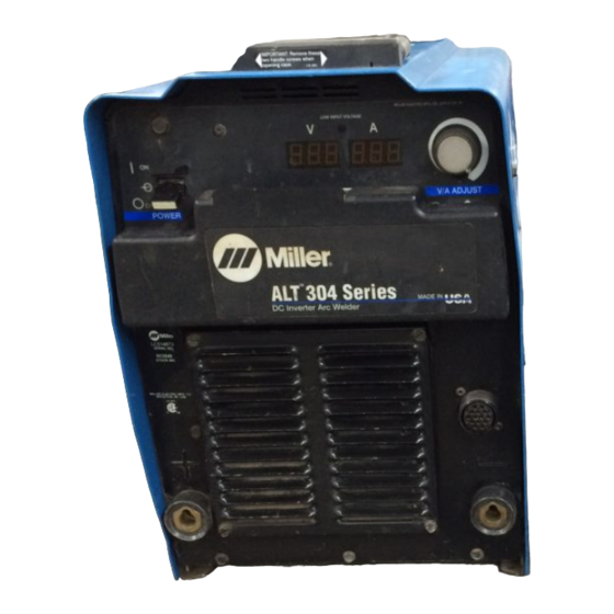
- Page 1 OM-2231 198 248J August 2003 Processes Multiprocess Welding Description Arc Welding Power Source ALT 304 Visit our website at www.MillerWelds.com...
- Page 2 We know you don’t have time to do it any other way. That’s why when Niels Miller first started building arc welders in 1929, he made sure his products offered long-lasting value and superior quality.
-
Page 3: Table Of Contents
TABLE OF CONTENTS SECTION 1 − SAFETY PRECAUTIONS - READ BEFORE USING ......1-1. -
Page 5: Section 1 − Safety Precautions - Read Before Using
SECTION 1 − SAFETY PRECAUTIONS - READ BEFORE USING som _nd_7/02 1-1. Symbol Usage Means Warning! Watch Out! There are possible hazards with this procedure! The possible hazards are shown in the adjoining symbols. This group of symbols means Warning! Watch Out! possible Y Marks a special safety message. - Page 6 ARC RAYS can burn eyes and skin. BUILDUP OF GAS can injure or kill. D Shut off shielding gas supply when not in use. Arc rays from the welding process produce intense D Always ventilate confined spaces or use visible and invisible (ultraviolet and infrared) rays that can burn eyes and skin.
-
Page 7: Additional Symbols For Installation, Operation, And Maintenance
1-3. Additional Symbols For Installation, Operation, And Maintenance FIRE OR EXPLOSION hazard. MOVING PARTS can cause injury. D Do not install or place unit on, over, or near D Keep away from moving parts such as fans. combustible surfaces. D Keep all doors, panels, covers, and guards D Do not install unit near flammables. -
Page 8: Principal Safety Standards
1-4. Principal Safety Standards Safety in Welding, Cutting, and Allied Processes, ANSI Standard Z49.1, Boulevard, Rexdale, Ontario, Canada (phone: from American Welding Society, 550 N.W. LeJeune Rd, Miami FL 33126 800−463−6727 or in Toronto 416−747−4044, website: www.csa−in- (phone: 305-443-9353, website: www.aws.org). ternational.org). -
Page 9: Section 1 − Consignes De Securite − Lire Avant Utilisation
SECTION 1 − CONSIGNES DE SECURITE − LIRE AVANT UTILISATION som _nd_fre 7/02 1-1. Signification des symboles Signifie Mise en garde ! Soyez vigilant ! Cette procédure présente des risques de danger ! Ceux-ci sont identifiés par des symboles adjacents aux directives. Ce groupe de symboles signifie Mise en garde ! Soyez vigilant ! Il y a des Y Identifie un message de sécurité... - Page 10 LES RAYONS DE L’ARC peuvent pro- LES ACCUMULATIONS DE GAZ ris- voquer des brûlures dans les yeux et quent de provoquer des blessures ou sur la peau. même la mort. Le rayonnement de l’arc du procédé de soudage D Fermer l’alimentation du gaz protecteur en cas de génère des rayons visibles et invisibles intenses non utilisation.
-
Page 11: Dangers Supplémentaires En Relation Avec L'installation, Le Fonctionnement Et La Maintenance
1-3. Dangers supplémentaires en relation avec l’installation, le fonctionnement et la maintenance Risque D’INCENDIE OU DES ORGANES MOBILES peuvent D’EXPLOSION. provoquer des blessures. D Ne pas placer l’appareil sur, au-dessus ou à proxi- D Rester à l’écart des organes mobiles comme le mité... -
Page 12: Principales Normes De Sécurité
1-4. Principales normes de sécurité Safety in Welding, Cutting, and Allied Processes, ANSI Standard Z49.1, Boulevard, Rexdale, Ontario, Canada (phone: from American Welding Society, 550 N.W. LeJeune Rd, Miami FL 33126 800−463−6727 or in Toronto 416−747−4044, website: www.csa−in- (phone: 305-443-9353, website: www.aws.org). ternational.org). -
Page 13: Section 2 − Introduction
SECTION 2 − INTRODUCTION 2-1. Specifications RMS Amps Input at Rated Load Output, 60 Hz 3-Phase at NEMA Rated Max. Load Voltages and Class I Output at Amperage Open- Rating Input Input Voltage Voltage Range in Range in 60% Duty 60% Duty Circuit Circuit... -
Page 14: Duty Cycle And Overheating
2-3. Duty Cycle And Overheating Duty Cycle is percentage of 10 min- utes that unit can weld at rated load without overheating. If unit overheats, output stops, a Help message is displayed and cooling fan runs. Wait fifteen min- utes for unit to cool. Reduce amper- age or voltage, or duty cycle before welding. -
Page 15: Section 3 − Installation
SECTION 3 − INSTALLATION 3-1. Selecting a Location 24 in (610 mm) Dimensions And Weight 78 lb (35.5 kg) 17 in (432 mm) 12-1/2 in (318 mm) Lifting Handles Movement Use handles to lift unit. Hand Cart Y Do not move or operate unit Use cart or similar device to move where it could tip. -
Page 16: Weld Output Receptacles And Selecting Cable Sizes
3-2. Weld Output Receptacles And Selecting Cable Sizes Total Cable (Copper) Length In Weld Circuit Not Exceeding 150 ft 200 ft 250 ft 300 ft 350 ft 400 ft 100 ft (30 m) Or Less (45 m) (60 m) (70 m) (90 m) (105 m) (120 m) -
Page 17: Optional Gas Valve Operation And Shielding Gas Connection
3-4. Optional Gas Valve Operation And Shielding Gas Connection Obtain gas cylinder and chain to running gear, wall, or other station- ary support so cylinder cannot fall and break off valve. Cylinder Regulator/Flowmeter Install so face is vertical. Gas Hose Connection Fitting has 5/8-18 right-hand... -
Page 18: Optional 115 Volts Ac Duplex Receptacle And Circuit Breakers
3-5. Optional 115 Volts AC Duplex Receptacle And Circuit Breakers 115 V 10 A AC Receptacle Power is shared between duplex receptacle and Remote 14 recep- tacle (see Section 3-3). Circuit Breaker CB1 Circuit Breaker CB2 CB1 protects duplex receptacle and 115 volts ac portion of Remote 14 receptacle from overload. -
Page 19: Connecting Input Power
3-7. Connecting Input Power Check input voltage available at site. The Auto-Line circuitry in this unit automatically links the power source to the primary voltage being applied. A unit can be connected to any input power between 208 and 575 VAC. -
Page 20: Section 4 − Operation
SECTION 4 − OPERATION 4-1. Front Panel Controls Power Switch best results, place Inductance/Dig control in wards minimum, short-circuit amperage at the maximum position. low arc voltage is the same as normal weld- The fan motor is thermostatically ing amperage. V/A (Voltage/Amperage) Control controlled and only runs when cooling is Switch... -
Page 21: Mode Switch Settings
4-2. Mode Switch Settings NOTE The Stick and CC modes provide the Adaptive Hot Start feature, which automatically increases the output amperage at the start of a weld should the start require it. This eliminates electrode sticking at arc start. Mode Switch Setting Mode Switch Setting Process... -
Page 22: Section 5 − Maintenance & Troubleshooting
SECTION 5 − MAINTENANCE & TROUBLESHOOTING 5-1. Routine Maintenance Y Disconnect power Maintain more often before maintaining. during severe conditions. 3 Months Repair Or Replace Replace Cracked Replace Damaged Or Torch Body Cracked Unreadable Cables Labels Repair Or Replace Cracked Cables And Cords Clean Tighten Weld... -
Page 23: Voltmeter/Ammeter Help Displays
5-3. Voltmeter/Ammeter Help Displays All directions are in reference to the front of the unit. All circuitry referred to is located inside the unit. HE.L P−1 Help 1 Display Indicates a malfunction in the pri- mary power circuit. If this display is shown, contact a Factory Autho- rized Service Agent. -
Page 24: Section 6 − Electrical Diagram
SECTION 6 − ELECTRICAL DIAGRAM Figure 6-1. Circuit Diagram OM-2231 Page 20... - Page 25 196 695−E OM-2231 Page 21...
-
Page 26: Section 7 − Parts List
SECTION 7 − PARTS LIST Hardware is common and not available unless listed. 802 906−C Figure 7-1. Parts Assembly OM−2231 Page 22... - Page 27 Item Dia. Part Mkgs. Description Quantity Figure 7-1. Parts Assembly ....+204 624 Wrapper, with Insulators .........
- Page 28 Item Dia. Part Mkgs. Description Quantity Figure 7-1. Parts Assembly (Continued) ... . . 211 096 Circuit Card Assy, Control (Inverter 400A) ......
- Page 31 Effective January 1, 2002 (Equipment with a serial number preface of “LC” or newer) This limited warranty supersedes all previous Miller warranties and is exclusive with no other Warranty Questions? guarantees or warranties expressed or implied. Call LIMITED WARRANTY − Subject to the terms and conditions APT, ZIPCUT &...
-
Page 32: Options And Accessories
Distributor Address City State For Service Call 1-800-4-A-Miller or see our website at www.MillerWelds.com to locate a DISTRIBUTOR or SERVICE AGENCY near you. Always provide Model Name and Serial/Style Number. Contact your Distributor for: Welding Supplies and Consumables Options and Accessories...