
Related Manuals for Miller AMD-4G


Summary of Contents for Miller AMD-4G
- Page 1 OM-179 082E March 2004 Processes Automatic Welding Description Wire Feeder AMD-4, AMD-4G, AMD-4GR, AMD−4GH, AMD-115G, AMD-115GR, And AMD-115GH Visit our website at www.MillerWelds.com...
- Page 2 We know you don’t have time to do it any other way. That’s why when Niels Miller first started building arc welders in 1929, he made sure his products offered long-lasting value and superior quality.
-
Page 3: Table Of Contents
TABLE OF CONTENTS SECTION 1 − SAFETY PRECAUTIONS - READ BEFORE USING ........1-1. -
Page 5: Section 1 − Safety Precautions - Read Before Using
SECTION 1 − SAFETY PRECAUTIONS - READ BEFORE USING som _8/03 1-1. Symbol Usage Means Warning! Watch Out! There are possible hazards with this procedure! The possible hazards are shown in the adjoining symbols. This group of symbols means Warning! Watch Out! possible Y Marks a special safety message. - Page 6 ARC RAYS can burn eyes and skin. BUILDUP OF GAS can injure or kill. D Shut off shielding gas supply when not in use. Arc rays from the welding process produce intense D Always ventilate confined spaces or use visible and invisible (ultraviolet and infrared) rays that can burn eyes and skin.
-
Page 7: Additional Symbols For Installation, Operation, And Maintenance
1-3. Additional Symbols For Installation, Operation, And Maintenance FIRE OR EXPLOSION hazard. MOVING PARTS can cause injury. D Do not install or place unit on, over, or near D Keep away from moving parts such as fans. combustible surfaces. D Keep all doors, panels, covers, and guards D Do not install unit near flammables. -
Page 8: Principal Safety Standards
1-5. Principal Safety Standards Safety in Welding, Cutting, and Allied Processes, ANSI Standard Z49.1, Boulevard, Rexdale, Ontario, Canada (phone: from American Welding Society, 550 N.W. LeJeune Rd, Miami FL 33126 800−463−6727 or in Toronto 416−747−4044, website: www.csa−in- (phone: 305-443-9353, website: www.aws.org). ternational.org). -
Page 9: Section 2 − Consignes De Sécurité − À Lire Avant Utilisation
SECTION 2 − CONSIGNES DE SÉCURITÉ − À LIRE AVANT UTILISATION som_fre 8/03 2-1. Signification des symboles Signifie « Mise en garde. Faire preuve de vigilance. » Cette procédure présente des risques identifiés par les symboles adjacents aux directives. Ce groupe de symboles signifie « Mise en garde. Faire preuve de vigi- Y Identifie un message de sécurité... - Page 10 LES RAYONS DE L’ARC peuvent cau- LES ACCUMULATIONS DE GAZ peu- ser des brûlures oculaires et cuta- vent causer des blessures ou même nées. la mort. Le rayonnement de l’arc génère des rayons visibles et D Couper l’alimentation en gaz protecteur en cas de invisibles intenses (ultraviolets et infrarouges) suscep- non utilisation.
-
Page 11: Autres Symboles Relatifs À L'installation, Au Fonctionnement Et À L'entretien De L'appareil
2-3. Autres symboles relatifs à l’installation, au fonctionnement et à l’entretien de l’appareil. Risque D’INCENDIE OU D’EXPLO- LES ORGANES MOBILES peuvent SION causer des blessures. D Ne pas placer l’appareil sur une surface inflam- D Se tenir à l’écart des organes mobiles comme les mable, ni au−dessus ou à... -
Page 12: Principales Normes De Sécurité
2-4. Principales normes de sécurité Safety in Welding, Cutting, and Allied Processes, norme ANSI Z49.1, Rexdale, Rexdale (Ontario) Canada M9W 1R3 (téléphone : (800) de l’American Welding Society, 550 N.W. LeJeune Rd, Miami FL 33126 463−6727 ou à Toronto : (416) 747−4044, site Web : www.csa−interna- (téléphone : (305) 443−9353, site Web : www.aws.org). -
Page 13: Section 3 − Installation
Weight Range Range Range Range Power Power Cord Cord AMD-4, AMD-4G, 50 To 780 ipm .023 To 1/8 in AMD-4GR, AMD-115G, (1.3 To 19.8 mpm) (0.6 To 3.2 mm) 16-1/2 lb And AMD-115GR 115 VDC, 0.75 A 115 VDC, 0.75 A 2 ft (0.6 m) -
Page 14: Typical Equipment Location
3-3. Typical Equipment Location Welding Power Source Weld Control Wire Drive Assembly Gas Cylinder Spool Support Automatic Welding Gun Side Beam 131 138-A 3-4. Installing Wire Guides And Drive Rolls When changing wire size or type, check drive roll and guide size (see Section 6-2). -
Page 15: Motor Mounting And Gun, Weld Cable, And Gas Connections
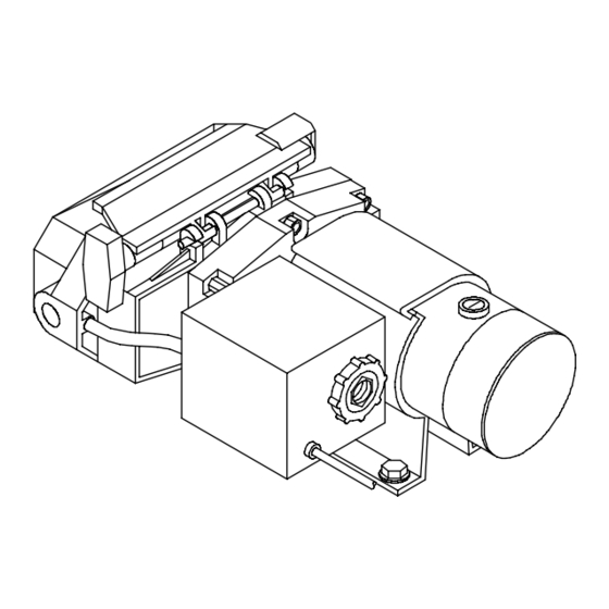
3-5. Motor Mounting And Gun, Weld Cable, And Gas Connections Drive motor must be isolated from weld potential. Insulator Plate When mounting motor, place factory-supplied insulator plate under motor mounting bracket to provide isolation. Customer Supplied Gas Hose Shielding Gas Valve Fitting Requires hose fitting with 5/8-18 right-hand threads. -
Page 16: Plug Connections
3-6. Plug Connections Weld Control Motor Control Cord (Not Supplied) Cord is available in 10 ft (3 m), 30 ft (9.1 m) or 50 ft (15.2 m) length. Motor/Drive Assembly To make connections, align key- way, insert plug, and tighten threaded collar. -
Page 17: Section 4 − Maintenance And Troubleshooting
SECTION 4 − MAINTENANCE AND TROUBLESHOOTING 4-1. Routine Maintenance Y Disconnect power before maintaining. 3 Months Clean Repair Or Replace Replace Unreadable Tighten Cracked Labels Weld Weld Terminals Cable Replace Cord Cracked Hose Cable Parts 6 Months Blow Out Or Clean Vacuum Inside. -
Page 18: Troubleshooting
Have Factory Authorized Service Agent check digital wire drive motor Tachometer board and encoder wire speed setting. disc. SECTION 5 − ELECTRICAL DIAGRAMS 180 590 Figure 5-1. Circuit Diagram For AMD-4G, AMD-4GR, And AMD-4GH OM-179 082 Page 14 Return To Table Of Contents... - Page 19 207 239 Figure 5-2. AMD-115G, AMD-115GR, And AMD-115GH OM-179 082 Page 15 Return To Table Of Contents...
-
Page 20: Section 6 − Parts List
......(AMD-4, AMD-4G, and AMD-4GR models) (including) .... - Page 21 ....047 636 HOUSING, plug+pins (AMD-4, AMD-4G, and AMD-4GR models) .....
- Page 22 To maintain the factory original performance of your equipment, use only Manufacturer’s Suggested Replacement Parts. Model and serial number required when ordering parts from your local distributor. 6-2. Drive Roll And Wire Guide Kits Wire Size V-GROOVE U-GROOVE VK-GROOVE UC-GROOVE 4 Roll 4 Roll 4 Roll...
- Page 23 Effective January 1, 2003 (Equipment with a serial number preface of “LC” or newer) This limited warranty supersedes all previous Miller warranties and is exclusive with no other Warranty Questions? guarantees or warranties expressed or implied. Call LIMITED WARRANTY − Subject to the terms and conditions Induction Heating Coils and Blankets below, Miller Electric Mfg.
- Page 24 Distributor Address City State For Service Call 1-800-4-A-Miller or see our website at www.MillerWelds.com to locate a DISTRIBUTOR or SERVICE AGENCY near you. Always provide Model Name and Serial/Style Number. Contact your Distributor for: Welding Supplies and Consumables Options and Accessories...