Vivotek ND8321 User Manual
8-ch/2-bay hdd /auto setup / auto adaptive stream/ hardware decoding
Hide thumbs
Also See for ND8321:
- User manual (184 pages) ,
- Quick installation manual (11 pages) ,
- Quick installation manual (11 pages)

Related Manuals for Vivotek ND8321


Summary of Contents for Vivotek ND8321
- Page 1 VIVOTEK - Built with Reliability ND8321 Network Video Recorder User’s Manual 8-CH • 2-Bay HDD • Auto Setup • Auto Adaptive Stream • Hardware Decoding Rev. 1.6.1.11 Rev. 1.0 Rev. 1.0 User's Manual - 1...
-
Page 2: Table Of Contents
VIVOTEK - Built with Reliability Table of Contents Revision History ..............................5 Chapter One Hardware Installation and Initial Configuration ..................6 Introducing ND8321 Network Video Recorder ....................... 6 Special Features ............................. 6 Safety ................................7 Physical Description ............................. 8 LED Indicators ..............................18 Power Up and Power Down .......................... - Page 3 VIVOTEK - Built with Reliability 3-4-14. Settings - System - Log ......................74 3-4-15. Settings - User .......................... 76 3-4-16. Settings - Storage ........................78 3-4-17. Settings - Network ........................80 Settings - Network - IP .......................... 80 Settings - DDNS ............................ 81 Settings - Service ..........................
- Page 4 VIVOTEK - Built with Reliability 5-4-1. Storage - Volume ..........................139 5-4-2. Storage - Disk ..........................143 5-5. Security ..............................145 5-5-1. User account ............................ 145 5-5-2. Access list ............................148 5-6. Alarm ................................149 5-6-1. General ............................149 5-6-2. Editing Alarms via Source, Action, and Schedule ................159 5-6-3.
-
Page 5: Revision History
VIVOTEK - Built with Reliability Revision History Rev. 1.0: Initial release. Read Before Use The use of surveillance devices may be prohibited by law in your country. The Network Camera is not only a high-performance web-ready camera but can also be part of a flexible surveillance system. -
Page 6: Chapter One Hardware Installation And Initial Configuration
Fisheye dewarp is also design in ND8321. ND8321 supports software dewarp of VIVOTEK fisheye cameras, allowing seamless display in a fisheye surveillance scenario. -
Page 7: Safety
VIVOTEK - Built with Reliability Safety Connect the system to an earthed main power outlet. Never open the housing of the power supply unit. Install and operate the system only in a dry, weather-proof location. Observe the following safety factors: Is there visible damage to the system or power cord •... -
Page 8: Physical Description
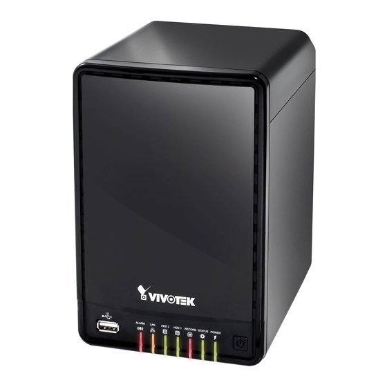
VIVOTEK - Built with Reliability Physical Description Front View 1 USB port 2 Alarm LED 3 LAN activity LED 4 HDD 2 activity LED 5 HDD 1 activity LED 6 Recording activity LED 7 System Status LED 8 Power LED... -
Page 9: Hardware Installation
VIVOTEK - Built with Reliability IMPORTANT: It is important to leave a clearance of 10cm to the rear side of the chassis. The clearance is required to ensure an adequate airflow through the chassis to ventilate heat. To ensure normal operation, maintain ambient airflow. - Page 10 VIVOTEK - Built with Reliability 3. Secure the HDD brakets to the hard drives. 4. Gently put the hard disks into drive bays with its label side facing the inside of the chassis and the connector side facing downwards. When the hard disks reach the bottom, use slightly more force to engage the the SATA connectors.
-
Page 11: Interface Connections
LAN / WAN NOTE: Although the system supports MAC Binding, the system should be able to detect VIVOTEK's cameras within the network regardless of the presence of a DHCP server. Ideally, cameras and the NVR should reside in the same subnet. If a camera's IP is changed for some reasons, the system should be able to detect its new IP. - Page 12 VIVOTEK - Built with Reliability IMPORTANT: Client computers should support IE10 browser at a minimum of 1280x960 resolution or higher. WARNING: If you connect the NVR to a PoE port of the AW-FED series PoE switch, make sure you turn off the PoE output on that specific port using the onboard DIP switch.
- Page 13 VIVOTEK - Built with Reliability Initial Configuration - via a Local Console A local console requires the following: 1. A monitor is connected via an HDMI cable. 2. A mouse and/or a keyboard are connected to the system. 3. It is presumed that the system has not been configured yet.
- Page 14 VIVOTEK - Built with Reliability 2. The system will then start to scan the local subnet for connected cameras. 3. All cameras detected on the network will be automatically selected. If necessary, deselect the cameras you want to exclude from the configuration. Click Continue to proceed.
- Page 15 VIVOTEK - Built with Reliability 4. The system will automatically create volumes from the installed disk drives. The process will take several minutes. 5. When done, the LiveClient screen will display, and, by default, the recording from the selected cameras will immediately take place.
- Page 16 ND8321 located in the same subnet. 4. Double-click on the ND8321 entry to start a web session with the NVR system. 5. The login page will prompt. Enter "admin" and "admin" as user name and password for access for the first time. Expand the menu on the right of the Login button. Select and click on the Settings button to begin your configuration.
- Page 17 VIVOTEK - Built with Reliability 6. On the Settings page, click on Storage > Volume to access your storage volume configuration. 7. On the Storage settings page, check if your hard drives are present and identified by your system. Click on the Create... button.
-
Page 18: Led Indicators
VIVOTEK - Built with Reliability LED Indicators 1 2 3 4 5 6 Name Behavior Definitions 1. Alarm LED Flashing Pre-defined alarms have been triggered (could be motion detection, digital inputs, etc.); the LED will stop flashing after 1 minute. -
Page 19: Power Up And Power Down
1. No storage system is completely fail-safe. Damage to data might occur due to file system corruption, operating system malfunction, virus infection, HDD component failures, and so on. Therefore, it is highly recommended to regularly back up your data, and VIVOTEK disclaims responsibilities of data loss or recovery. -
Page 20: Section One Management Over A Local Console
VIVOTEK - Built with Reliability Section One Management over a Local Console Chapter Two Introduction to the Local Console Interface Local console 20 - User's Manual... - Page 21 VIVOTEK - Built with Reliability By default, a live view appears on an HDMI monitor. The interface architecture of the local console is illustrated as follows: LiveView Main screen Main control portals Layout DI/DO Search panel Search recording clip Storyboard...
-
Page 22: How To Begin
VIVOTEK - Built with Reliability 2-1. How to Begin 1. How to access the Configuration Portal? Make sure a mouse is attached to your NVR. Move your mouse cursor, and the Configuration Portal will appear on screen. For all the configurable options available through this portal, please refer to Chapter 3 on page 34. - Page 23 VIVOTEK - Built with Reliability PTZ control panel for ordinary PTZ control panel for joystick type PTZ PTZ type 2. How to retrieve and access recorded videos? 2-1. One is to access the video clips taken within 2 hours. Left-click to select a view cell, and then click on the Recording clips button.
- Page 24 VIVOTEK - Built with Reliability The Playback window will prompt, and a playback begins from the point in time you selected, e.g., 30 seconds ago. This function allows you to quickly review what has just happened. 2-2. Another way to access past videos is to open the Search recording clips window. Move your mouse cursor to display the Configuration Portal (without selecting any view cell).
- Page 25 VIVOTEK - Built with Reliability 3. How to recieve system alarm? Please refer to page 61 for how to configure system alarm triggers. When the alarm is triggered, e.g., by digital inputs or motion detection, an alarm message will prompt on the screen.
- Page 26 VIVOTEK - Built with Reliability 4. Why live view is unavailable? The default live view receives a camera's stream #2. If a camera's stream #2 is configured using MPEG-4 as the video codec, the following message will prompt. You can go to the Settings > Camera > Media > Video window to configure the video codec of stream #2 into H.264.
- Page 27 VIVOTEK - Built with Reliability 5. How do I move to another layout page? Move your cursor to the right hand side of your screen. The page turner buttons will appear as shown below. For example, if you have 8 cameras placed on 2 2x2 layout pages, use these buttons to visit different pages.
-
Page 28: Operation On Camera View Cell
VIVOTEK - Built with Reliability 2-2. Operation on Camera View Cell 2-2-1. PTZ Panel Once you selected a camera, click on the PTZ button on a camera portal. The PTZ panel will prompt. Below are the description of its functions:... - Page 29 VIVOTEK - Built with Reliability Below is the PTZ panel that appears with ordinary PTZ cameras. List of preset positions Speed selector Focus far Focus near Zoom in Zoom out Starts patrol 1. PTZ control: Click on the arrow buttons to move towards the direction you wish to move to.
-
Page 30: Pip (Picture In Picture) Panel
VIVOTEK - Built with Reliability 2-2-2. PiP (Picture in Picture) Panel PiP is short for Picture in Picture, a function that provides digital zoom into a live video. When activated, a Global view window will appear at the lower right of the view cell as shown below. -
Page 31: Play Recording Clips Panel
VIVOTEK - Built with Reliability 2-2-3. Play Recording Clips Panel The Play Recording Clips function provides a shortcut to the latest recordings on the system. You can select 30 secs, 1 min, 3 mins, 10 mins, and 60 mins for an immediate playback. -
Page 32: Di/Do
VIVOTEK - Built with Reliability 2-2-4. DI/DO The DI/DO panel provides a glimpse of all DI and DO signal statuses from the connected cameras. You can manually trigger a digital output by clicking on its indicators. When a digital input is triggered, its status will also be indicated on the panel. -
Page 33: Right-Click Commands
VIVOTEK - Built with Reliability 2-2-6. Right-click Commands Left-click to select a camera. Right-click to display the selection menu. 1. Camera information: Click to display camera name, resolution, codec, or frame rate on the view cell. The information will display on the upper left corner of a view cell. -
Page 34: Chapter Three Configuation Using The Local Console
VIVOTEK - Built with Reliability Chapter Three Configuation Using the Local Console The Main Control Portal 3-1. Layout Move your mouse cursor across the screen to display the portal. The first functional button is Layout. You can select the 1x1, 1x3, 2x2, 3x3, 1+5, 1+3, 1+1+3, or 1+3+3 layout as the screen display. -
Page 35: Search Recording Clips
VIVOTEK - Built with Reliability 3-3. Search recording clips 3-3-1. Basic Search Click the button to start searching for recorded clips. A confirm box will prompt. Enter User name and Password to proceed. The search and calendar view will appear. Select a day on the calendar when the the recordings took place (the days with recorded clips will be highlighted in blue and green). - Page 36 VIVOTEK - Built with Reliability The timeline bar enables quick skimming through the recording. Its functions are described as follows: Span of existing Current time recording indicator Functional buttons Control buttons Timeline scale Buttons Description Time scale selector. Use the buttons to select the span of time displayed on the tool bar.
- Page 37 VIVOTEK - Built with Reliability When playing the video recorded by a fisheye camera, the fisheye display options will be available on screen. You can click to select the 1O, 1P (Panoramic), 1R (Regional), or 1O3R (1 Original and 3 Regional) modes. If 1P, 1R, or 1O3R mode is selected, you can exert the mouse control on screen, such as swiping the view, or hold down the mouse button and swipe the field of view.
- Page 38 VIVOTEK - Built with Reliability Note that to export a video segment from the playback timeline, 1. Click on the Export button 2. Insert a USB drive formatted in the FAT format. 3. Select the "From time" by clicking on the timeline. You can also manually enter the "From time"...
-
Page 39: Advanced Search
VIVOTEK - Built with Reliability 3-3-2. Advanced Search Click on the Advanced search button on the upper left of the screen to enter the Advanced Search mode. You can specify the search criteria by selecting the devices to be involved in the advanced search. - Page 40 VIVOTEK - Built with Reliability You can then specify the start time and end time to form a span of time to be searched. You can also determine what alarms will be included in the search. 40 - User's Manual...
- Page 41 VIVOTEK - Built with Reliability You can select what types of triggers were associated with the recordings you want to find. When done with the selection, click on the Search button. In the sample screen below, a list of alarms is displayed, and you can double-click on any of them to replay the moment when the alarm was triggered.
-
Page 42: Storyboard
VIVOTEK - Built with Reliability 3-3-3. Storyboard The Storyboard interface provides a glimpse of past recordings over a timeline. It looks like doing the film editing after a film was shot. To enter the Storyboard window, click on the Storyboard shortcut on the upper-left of screen. - Page 43 VIVOTEK - Built with Reliability Mouse over the line of snapshots to display its time of recording. Click on a snapshot of your interest. The time of recording is displayed on top of it. The detailed search is based on a narrow-down criteria. The search begins from a 24-hour time span, and then moving in to a 4-hour, 1-hour, 10-minutes, and 2-minutes span.
- Page 44 VIVOTEK - Built with Reliability If you find yourself in the wrong segment on the timeline, use the buttons on the upper-right of the screen to travel. The definitions of these buttons depend on the time span of your current position. For example, if you are in a 4-hour time span, the "Back to previous state button"...
- Page 45 VIVOTEK - Built with Reliability The playback window will appear. Please refer to page 36 for the operation details. 17:15:41 2014.03.14 To return to the Live View window, click on the Back to Search recording clips button the Back to Liveview button on the upper-left of the screen.
-
Page 46: Settings
VIVOTEK - Built with Reliability 3-4. Settings 3-4-1. Settings - Overview Click the Settings button to start the camera and system settings window. A confirm box will prompt. Enter User anme and Password to proceed. The system will default to the overview page displaying the camera connection and storage statuses. -
Page 47: Settings - Camera - Management
VIVOTEK - Built with Reliability The Camera menu provides access to Management, Recording, Media, Image, Camera options, and PTZ settings pages. 3-4-2. Settings - Camera - Management On the camera Management page, you can configure the following: 1. Recruit or disband cameras. - Page 48 VIVOTEK - Built with Reliability To recruit cameras: 1. Click on the Add button. A list of cameras in the same subnet will appear. 2. Click the Add button, the camera will be placed at an unoccupied position. You may also expand the menu on the side of the Add button to select a position number.
- Page 49 VIVOTEK - Built with Reliability To disband cameras: 1. Click on the Remove button. A list of cameras will appear. 2. The Remove button will turn yellow . Mouse over to the camera you want to remove, and its entry will display the Remove message.
- Page 50 VIVOTEK - Built with Reliability Network On the Network tabbed window, you can configure the network type, IP address, and the connection ports for video streaming. You can select DHCP as the method for cameras to acquire IP addresses, or you can manually configure static IPs for a single or all cameras.
- Page 51 VIVOTEK - Built with Reliability Camera position To change a camera's position on the Liveview layout, click and drag a camera to an unpopulated position. Note that you can not swap the positions of two cameras by dragging a camera onto a position already populated by the other. Also, the camera index number on the management list is not affected by the change of positions.
-
Page 52: Settings - Camera - Recording
VIVOTEK - Built with Reliability 3-4-3. Settings - Camera - Recording Recording options On the camera Recording page, you can configure the following: 1. Configure the duration of camera events, for the concern that camera can be too frequently triggered. - Page 53 VIVOTEK - Built with Reliability Recording Schedule By default, all video feeds from cameras are recorded at all time. You can modify the recording task using the schedule tool: 1. Click to select a recording condition's checkbox - 1. Continuous recording...
-
Page 54: Settings - Camera - Media
VIVOTEK - Built with Reliability 3-4-4. Settings - Camera - Media Stream management The stream here refers to the recording stream, namely, Stream 1. You can use these preset conditions to configure the resolution, image quality, frame rate, and the bandwidth consumption of the recording stream on this window. - Page 55 VIVOTEK - Built with Reliability Video The Video window allows you to configure all video streams (the no. of stream available can be different for different models). You can configure the following: 1. Codec: video compression codec in H.264 or MJPEG. Note that MPEG-4 is not supported for Liveview.
-
Page 56: Settings - Camera - Image
VIVOTEK - Built with Reliability 3-4-5. Settings - Camera - Image Display The Display window allows users to tune the image display options: 1. Video name: the video name is displayed on the title bar that is displayed on each view cell. - Page 57 VIVOTEK - Built with Reliability Image adjustment The Image adjustment window allows users to tune the basics about image display options: 1. Color: Select to display image as color or black and white. 2. Brightness. 3. Saturation. 4. Contrast. 5. Sharpness.
-
Page 58: Settings - Camera - Motion Detection
VIVOTEK - Built with Reliability 3-4-6. Settings - Camera - Motion Detection Motion Detection To set up a detection window: 1. Select a camera by a single click. 2. Use the PTZ panel to move to a field of view where you want to place a detection window. -
Page 59: Settings - Camera - Ptz Settings
VIVOTEK - Built with Reliability 3-4-7. Settings - Camera - PTZ settings To configure PTZ preset positions: 1. Select a PTZ camera by a single click. 2. Use the PTZ panel to move to a field of view where you want to designate as a preset position. - Page 60 VIVOTEK - Built with Reliability To configure a patrol: 1. Click to enter the Patrol menu. Select a preset position if you want to change its position on the patrolling order. 2. Click the up and down buttons to change the position on the order, or click the remove button to disband a position from the order.
-
Page 61: Settings - Alarm - Alarm
VIVOTEK - Built with Reliability 3-4-8. Settings - Alarm - Alarm The events reported from individual cameras' digital inputs, digital outputs, and motion detection can be accommodated in the NVR system's alarm settings. These events will then be reported or trigger corresponding actions as follows: 1. - Page 62 VIVOTEK - Built with Reliability To create an alarm, 1. Click on the Add button You can manually enter a name for the current setting. You can enter up to 16 numeric or alphabetic characters for the name, including symbols such as [0-9][a-z][A-Z][_][ ]. You can also designate the interval between one alarm and the next triggered alarm to avoid the situation that the alarms can be too frequently triggered.
- Page 63 VIVOTEK - Built with Reliability 3. On the Trigger window, select system triggering conditions, or one or more cameras by selecting their checkboxes. The number of DI or DOs on each camera is automatically detected and displayed through individual checkboxes. The Motion detection function, if there are many detection windows configured on a camera, is all triggered by one checkbox.
- Page 64 VIVOTEK - Built with Reliability 4. On the Action window, you can select the Action type from a drop-down menu. The configuration details of each action type is discussion below. 4-1. Recording - When an event is triggered, the selected camera will record a video footage of the length defined by the pre-/post-event setting, to the NVR system.
- Page 65 VIVOTEK - Built with Reliability The Email subject and addresses can be composed of 254 characters in numeric or alphabetic characters including: [0-9][a-z][A-Z][_][ ][-][.][,][@]. You can enter the addresses of multiple recipients. Use semicolons, (;), to separate the addresses of multiple recipients.
- Page 66 VIVOTEK - Built with Reliability 4-4. FTP - Snapshots from specified cameras can be uploaded to an FTP site on the occurrence of an event. Enter the FTP site address in the dotted-decimal notation, e.g., 159.22.151.20. Enter the login name and password for the user account. You can enter a directory name you prefer on the FTP site.
- Page 67 VIVOTEK - Built with Reliability 4-5. Camera DO - A triggered alarm triggers a camera's DO, e.g., an alarm siren. 4-6. Camera preset points - A PTZ capable camera can move its lens to the preset position in case of a triggered alarm. For example, a triggered sensor may indicate an area of interest has been intruded, and a camera's field of view should be moved to cover that area.
- Page 68 VIVOTEK - Built with Reliability 5. On the Schedule page, you can select to activate or de-activate alarm triggers throughout a specific timeline. For example, in some situations you can disable the alarm triggers during the office hours, and choose to enable the triggers only during the off-office hours.
-
Page 69: Settings - Alarm - Email
VIVOTEK - Built with Reliability 3-4-9. Settings - Alarm - Email This window provides an interface where you can configure the connection to a Mail server. Via the Mail server, the system can deliver Emails containing system alarm messages to multiple receivers. -
Page 70: Settings - System - Information
VIVOTEK - Built with Reliability 3-4-10. Settings - System - Information On this window, you can configure the following: 1. Change the system name. 2. Select the UI text language. 3. Configure system time, time zone, and if you are connected to a DNS server where Auto Daylight Saving time can be applied, you can acquire the associated setting from a server within your network. -
Page 71: Settings - System - Maintenance
VIVOTEK - Built with Reliability 3-4-11. Settings - System - Maintenance If the need arises for updating system firmware, acquire the update from VIVOTEK's technical support or download site. Locate the firmware binaries, and click the Import button. The upgrade should take several minutes to complete. -
Page 72: Settings - System - Display
VIVOTEK - Built with Reliability 3-4-12. Settings - System - Display On this page, you can configure the system to consecutively display (rotate) cameras' view cells on the Liveview window. For example, if you have 8 cameras in 2 2x2 layouts, the rotation can let you see the live views of all cameras by every few seconds. -
Page 73: Settings - System - Ups
VIVOTEK - Built with Reliability 3-4-13. Settings - System - UPS On this page, you can configure the system to gracefully shut down when UPS battery is lower than a certain level. You may also let it shut down when the estimated sustainable time is reached. -
Page 74: Settings - System - Log
VIVOTEK - Built with Reliability 3-4-14. Settings - System - Log System logs are categorized as System, Recording, User, and Error. To display system logs, select a range of time and click on the Search button. You can search for past logs in each category window. - Page 75 VIVOTEK - Built with Reliability User's Manual - 75...
-
Page 76: Settings - User
VIVOTEK - Built with Reliability 3-4-15. Settings - User The User window allows you to create more uers, to change user password, and place limitations on users' privileges and administration rights. Up to 16 users can be created, including the default administrator. - Page 77 VIVOTEK - Built with Reliability To create or edit users, 1. Select a User group by unfolding its pull-down menu. Select either an Administrator or regular user as the user group. 2. Enter the User name and password. The max. number of characters for a user name is 64, with alphabetic and numeric characters including [0-9][a-z][A-Z][_][ ][-][.][,][@].
-
Page 78: Settings - Storage
VIVOTEK - Built with Reliability 3. If you are creating a regular user with limited access to cameras, deselect the checkboxes by the cameras to deny the user access. 4. Click Apply to close the configuration window. Repeat the process to create more users. - Page 79 VIVOTEK - Built with Reliability Attribute: The various attributes can vary from different HDD manufacturers. Value: Value for the currently selected attribute. Worst: Worst value acquired for that attribute. Threshold: A predefined threshold or triggering value. The threshold below which the normalized value will be considered exceeding specifications.
-
Page 80: Settings - Network
VIVOTEK - Built with Reliability 3-4-17. Settings - Network Settings - Network - IP DHCP: Default is selected, the server obtains an available dynamic IP address assigned by the DHCP server each time the system is connected to the LAN. -
Page 81: Settings - Ddns
VIVOTEK provides Safe100.net, as a free DDNS dynamic domain name service for users who want access from the internet or a domain name service for the NVR. VIVOTEK maintains a database of product MAC addresses for the Safe100.net service, and you can apply one domain name for each NVR system. -
Page 82: Settings - Service
HTTPS encrypted connection is enabled by default. Instead of a web console, you can also access the NVR and the subordinate cameras using the iViewer and VIVOTEK's VAST software. The NVR can be managed as one of the sub-stations in a hierarchical device structure. -
Page 83: Information
VIVOTEK - Built with Reliability 3-5. Information This window shows the revision number of the firmware running on this machine. User's Manual - 83... -
Page 84: Section Two Management Over A Web Console
VIVOTEK - Built with Reliability Section Two Management over a Web Console There are two different interfaces on the system: 1. One is connecting mouse and keyboard, and an HDMI cable to a TV screen or monitor. The local management thus made is described in Section One of this manual. -
Page 85: Chapter Four Login And Getting Started
VIVOTEK - Built with Reliability Chapter Four Login and Getting Started 4-1. Login This is the login page on the browser. The minimum for resolution is 1280x960. If you enable the IE7 compatible mode when using the IE8 browser, please disable the compatibility function. - Page 86 VIVOTEK - Built with Reliability You may login to a different software utility by unfolding the side panel on the Login button. You can also select a different language using the Multilingual selector menu on the lower left corner of the Login screen. The functional items, menus, and dialogues will then be displayed using the selected language.
- Page 87 VIVOTEK - Built with Reliability Login options: You may also mouse over the Login button to display the login options. You can then enter the Liveview, Playback, or Settings window. The NVR system features a very simple UI structure which consists of a Liveview window, a Playback utility, and a system Settings window.
- Page 88 VIVOTEK - Built with Reliability IMPORTANT: 1. Before operating the NVR, make sure you have properly installed hard drives and configured the storage volumes. Otherwise, you will not be able to operate or try some of the system's functionality. 2. Since the NVR system comes with 32-bit plug-ins for screen control, if your PC runs a default 64-bit IE browser and you manually enter the NVR's address on the browser, your browser session may malfunction.
-
Page 89: Graphical Layout And Screen Elements - Liveview
VIVOTEK - Built with Reliability 4-2. Graphical Layout and Screen Elements - Liveview Layout Camera list Layout contents Logo & Menu Alarm panel panel Viewcell panel Once you log in, the system defaults to the Liveview page, which provides access to other configuration utilities, live view screen, and other functional panels. -
Page 90: Camera List Panel
VIVOTEK - Built with Reliability 4-2-1. Camera List Panel The camera list displays the recruited cameras by the sequential numbering order you configured in the System Settings utility. Sorting criteria Camera thumbnails Page switcher Depending on the size and screen resolution of your monitor, the snapshots of 8 cameras are displayed in this panel. - Page 91 VIVOTEK - Built with Reliability * Snapshot: the camera's image snapshot is replenished every 5 minutes. If a camera is disconnected, the last image taken will be used to represent a camera. * Camera index & Camera name: Placing the mouse cursor on top of a camera text displays the camera index number and the camera name.
-
Page 92: Layout
VIVOTEK - Built with Reliability 4-2-2. Layout By default, 5 typical layouts are provided for the user. They include: 1x1, 1+3, 2x2, 1+5, and 3x3. System default is the 3x3 layout. Cameras that do not fit into the first page of a layout, say, a 2x2 layout, will be displayed on the succeeding layout pages. -
Page 93: Layout Contents
VIVOTEK - Built with Reliability 4-2-3. Layout contents A few functional buttons are available on the Layout contents page. Clears all view cells on the current layout. Full view: extends the view cells on the current layout to the full of the screen. -
Page 94: View Cell Panel
VIVOTEK - Built with Reliability 4-2-5. View Cell panel A single view cell is shown below. Each view cell contains a video stream display area, an information bar, and functional buttons at the bottom. A view cell is displayed in Normal, Focused, or Maximized mode. - Page 95 VIVOTEK - Built with Reliability A view cell attempting to connect to a network camera will look like this. If the connection attempt takes a long time, it may result from network problems or incorrect configuration with video streaming. For example, you may have configured the camera to be streaming a 5MP stream.
- Page 96 VIVOTEK - Built with Reliability Information Bar Status icon Camera index Video time Status icon Description Connected with live streaming; a single click on this icon can trigger a manual recording. Connected and recording video to system storage. Disconnected or trying to establish a connection.
- Page 97 VIVOTEK - Built with Reliability The time display format is as follows: yyyy/m/d/yyyy hh:mm:ss 2014.05.05 16:15:41 Tool Bar Buttons Buttons Description Resumes streaming. Pauses a video stream. Adds a Bookmark (that saves a short description and a one-minute footage from the current feed) Takes a snapshot.
- Page 98 VIVOTEK - Built with Reliability Buttons Description Volume controller Fisheye display modes - if the view cell contains video from a fisheye camera, the fisheye display mode selector will be available: 1O: the orginal circular view. 1P: the panoramic view.
- Page 99 VIVOTEK - Built with Reliability Below are two bookmarks (yellow tags) shown along with a recorded video in the Playback utility screen. Bookmarks help find and retrieve important moments in a recoded video. NOTE: Bookmarks will be erased if the user/system erases the video clips they were appended to. For example, system will recycle storage space by deleting old videos along with their bookmarks.
- Page 100 VIVOTEK - Built with Reliability 4. Clear: This button removes camera from the current view cell. The view cell will then be available for other cameras 5. Mute and Unmute: These buttons stops or resumes audio from a live stream.
- Page 101 VIVOTEK - Built with Reliability 9. Volume controller: The volume control takes effect when audio input from the network camera is available. Audio is heard only from a focused window, one that you selected by a mouse click from the Liveview panel.
- Page 102 VIVOTEK - Built with Reliability 1R (Regional view) 1R View (Single Regional View) Zoom Out Zoom In Zoom in/out & all-directional navigation control The 1R mode (or rectilinear) provides access to one image section within the hemisphere. You can zoom in or out (using the mouse wheel or PTZ panel) or travel through to other areas within the hemisphere using simple mouse clicks and drags.
-
Page 103: Ptz Panel
VIVOTEK - Built with Reliability 4-2-6. PTZ panel The PTZ panel takes effect for cameras that come with mechanical PTZ functions. It does not support digital PTZ functions. To utilize its functions, select a view cell populated by a PTZ camera, such as a speed dome. - Page 104 VIVOTEK - Built with Reliability PTZ presets: If your PTZ cameras have preset locations, click on the button to unfold the preset menu. Click on any of the preset locations to move to the area of your interest. Refer to your camera's User Manual for how to configure preset locations.
-
Page 105: Alarm Panel
VIVOTEK - Built with Reliability Auto pan/patrol controller: These buttons provides pan and patrol functions provided that preset locations have been configured on the camera. For a speed dome camera, the pan command tells the camera to continuously pan 360 degrees until it is stopped by a user command. - Page 106 VIVOTEK - Built with Reliability If an event is configured with a recording action, there will be a play button to the left of the alarm message. The alarm playback window will begin playback of a footage taken 10 seconds before the occurrence of an alarm.
- Page 107 VIVOTEK - Built with Reliability Move your cursor over an alarm with a recorded footage. The Play button will become available. The following buttons are available in the alarm playback window. Buttons Description View live video: displays the live view streaming instead of the alarm recording.
- Page 108 VIVOTEK - Built with Reliability Incoming Alarms New alarms will be indicated by the messages in bold letters, the alarm bell icons, and the increasing number of unread messages on the title bar. 108 - User's Manual...
-
Page 109: Graphical Layout And Screen Elements - Search Recording Clips
VIVOTEK - Built with Reliability 4-3. Graphical Layout and Screen Elements - Search recording clips Layout contents Logo & Menu Camera list Calendar Alarm panel Playback panel The screen elements of the Playback window are described as follows: Item Name... -
Page 110: Camera List Panel
VIVOTEK - Built with Reliability 4-3-1. Camera List Panel The camera list displays the 8 recruited cameras by the sequential numbering order you configured in the System Settings window on page 129. The elements in the Camera list on a Search recording clips window are identical to those on a Liveview window. -
Page 111: Search Recording Clips Layout
VIVOTEK - Built with Reliability 4-3-2. Search Recording Clips Layout 3 types of layouts are provided for the Search recording clips window: 1x1, 2x2, and 1+3. In the Search recording clips window, users can simultaneously playback up to 4 recorded videos. -
Page 112: View Cells In Search Recording Clips
VIVOTEK - Built with Reliability 4-3-4. View Cells in Search Recording Clips The view cells in Liveview and Playback windows are similar. Their differences are listed as follows: 1. 3 simple layout types are supported as previously described. 2. The information bar displays camera index and video time information only. - Page 113 VIVOTEK - Built with Reliability Search Recording Clips Control Panel Timeline slider Span of existing recording Control buttons Playback info Timeline zoomer The time slide bar enables quick skimming through the recording. Its functional buttons are described as follows: Buttons...
- Page 114 VIVOTEK - Built with Reliability The time line shows the length of existing recording taken on a specific time span. You can use the timeline zoomer to scale down the span of time. For example, if the time span is reduced to 1 hour, then each section on the time line represents 15 minutes of recording.
-
Page 115: Alarm Panel
VIVOTEK - Built with Reliability 4-3-5. Alarm Panel The alarm panel displays the alarms or bookmarks recorded by the day of recording. Two additional buttons are available: Page selector and Alarm filter. Page selector Alarm filter See page 149 for how to configure alarms. -
Page 116: Calendar Panel
VIVOTEK - Built with Reliability 4-3-6. Calendar Panel Double-click on any of the existing cameras to display the Calendar panel. Days with recorded videos will be highlighted in blue regardless of the length of existing recordings that occurred in that day. You may then click on a day to begin viewing the past recordings. -
Page 117: Chapter Five System Settings
VIVOTEK - Built with Reliability Chapter Five System Settings The Settings window is accessed by clicking on the Settings button on the Logo panel. You will enter the Overview of the Settings window. All the configuration menus are placed under 7 major categories: System, Network, Camera, Storage, Security, Alarm, and Logs. -
Page 118: System
VIVOTEK - Built with Reliability Pnotify - During the configuration process, configuration errors or information will be indicated by a small pnotify message boxes on the lower right of the screen. 5-1. System 5-1-1. System - General The system general information window allows you to change the system host name, time zone, system date and time, and set up a scheduled reboot of the system. -
Page 119: System - Upgrade
5-1-2. System - Upgrade If the need arises for updating system firmware, acquire the update from VIVOTEK's technical support or download site. Locate the firmware binaries, and click Upgrade. The upgrade should take several minutes to complete. Note that during the upgrade, the recording task will be interrupted. -
Page 120: System - Backup
VIVOTEK - Built with Reliability 5-1-3. System - Backup On this window, you can perform 3 maintenance tasks: 1. Backup - You can backup your system configuration using the Backup function. Click Backup, a message window will prompt. Click Save to preserve your system configurations. - Page 121 VIVOTEK - Built with Reliability 2. Restore - If you have a previously-saved profile, you can restore your previous configuration. Click the Restore button. A file location window will prompt. Locate the backup file, and click Open. The Restore process will take several minutes to complete, and system operation will be interrupted during the process.
-
Page 122: System - Maintenance
VIVOTEK - Built with Reliability 5-1-4. System - Maintenance This window displays basic information of various aspects, including CPU and memory usage, LAN port operation and its bonding, disk drive temperatures, and UPS status. The Reboot button is used to restart the NVR system. -
Page 123: Ups Support
VIVOTEK - Built with Reliability UPS support Once a UPS is connected via the USB interface, the NVR system supports the cooperating protection against power outage. The UPS status [model name, status (Online or On battery), battery charge level] is listed in the Maintenance page as shown below. -
Page 124: Network
VIVOTEK - Built with Reliability 5-2. Network 5-2-1. Network - General Address settings: Get IP address automatically: Select this option to obtain an available dynamic IP address assigned by the DHCP server each time the system is connected to the LAN. -
Page 125: Network - Ddns
VIVOTEK provides Safe100.net, as a free DDNS dynamic domain name service for users who want access from the internet or a domain name service for the NVR. VIVOTEK maintains a database of product MAC addresses for the Safe100.net service, and you can apply one domain name for each NVR system. - Page 126 VIVOTEK - Built with Reliability Enter a Host name, Email address, and password twice, and then click Register to proceed. The acceptable characters for email address are: [0-9][a-z][A-Z][!][#][$][%][‘][*][+][-][/][=][?] [^][_][`][{][|][}][~][.]. Two successive periods, [..], are not acceptable. The address filed can accommodate up to 254 characters.
-
Page 127: Network - Service
Instead of a web console, you can also access the NVR and the subordinate cameras using the iViewer and VIVOTEK's VAST software. The NVR can be managed as one of the sub-stations in a hierarchical device structure. -
Page 128: Network - Utility
VIVOTEK - Built with Reliability 5-2-4. Network - Utility Use the test utility to test the connectivity with a network device, such as a camera. Test results will be displayed by a message prompt. Failure to reach a device displays the message below. -
Page 129: Camera
The camera window provides management tools to recruit or disband cameras from your NVR configuration. 1. Search: The Search button allows you to locate all VIVOTEK cameras within a local network. Use the check circles on top to display all cameras only cameras that have not been recruited. - Page 130 VIVOTEK - Built with Reliability On a listed camera, mouse over to the left of the entry to display the Add button. Click on the button. To deselect a camera, use the Remove button. Select a camera index number from the pull-down menu. The first unused number will be listed.
- Page 131 VIVOTEK - Built with Reliability The legends used in the camera list are described below: Selected Move hover (#) numbered: Camera index. Name: Camera name. IP address: A valid camera configuration enables the IP address as a hyper link. You can click on the hyper link to open an IE web console with the camera.
- Page 132 VIVOTEK - Built with Reliability Left-click to select a camera, and edit the Connection and Recording configuration below: 1. Connection - You can rename the camera, and if your camera comes with password protection, enter its User name and Password here. Otherwise, you will not be able to manage or access the camera.
- Page 133 VIVOTEK - Built with Reliability 2. Recording: 2-1. Keep all recordings for maximum * days - determine the life span of recordings in your system. Usually old recordings will be erased when the storage volumes become full. When a storage volume is 90% full, the recorded videos taken on the oldest day (from every camera) will be erased.
- Page 134 VIVOTEK - Built with Reliability 4. Save: Click the Save button to preserve your configuration whenever changes are made to the configuration or when you are leaving this page. IMPORTANT: Leaving the Camera - General page without saving your configuration, you will lose your configuration changes.
-
Page 135: Camera - Video
VIVOTEK - Built with Reliability 5-3-2. Camera - Video The Video page determines the Liveview and recording streams of individual cameras in terms of compression format, video resolutions, frame rate, and the constant bit rate settings. The constant bit rate setting is especially important in that the sum of bandwidth consumed for all recording streams must not exceed the 32Mbps threshold. -
Page 136: Camera - Motion Detection
VIVOTEK - Built with Reliability Fixed quality: This guarantees all video frames in a video stream will be delivered using the same image quality. If network congestion or in the case of insufficent bandwidth, some video frames may be dropped in order to maintain image quality. -
Page 137: Camera - Schedule
VIVOTEK - Built with Reliability 5-3-4. Camera - Schedule The camera recording schedule can be configured down to an hourly basis. The default settings for cameras is to record videos at all time. To set up a schedule, 1. Select a camera from the list using a single mouse click, 2. - Page 138 VIVOTEK - Built with Reliability The Event recording is triggered by digital inputs or motion detection. You can click on the setup button to select or deselect the triggering options. 138 - User's Manual...
-
Page 139: Storage
VIVOTEK - Built with Reliability 5-4. Storage 5-4-1. Storage - Volume Each hard drive installed into the system will be considered as a candidate for composing a single-disk volume. Single disk: The single disk configuration provides no fault tolerance. The system stores video recordings to one or more single disk volumes in a consecutive order. - Page 140 VIVOTEK - Built with Reliability The legends used in the Volume list are described below: Selected (#) numbered: Volume index. Disk: Member(s) of this volume. Cacacity: Total usable capacity size in Gigabytes. Used: The used capacity in Gigabytes. Status: The status display when processing volume configuration, deleting, and formatting a volume.
- Page 141 VIVOTEK - Built with Reliability 2. The creation progress will be shown at the Status column. When completed, and if you already have cameras in your configuration, the recording task will immediately begin. To delete a storage volume: 1. Click to select a storage volume from the list.
- Page 142 VIVOTEK - Built with Reliability To format a storage volume: You may also format an existing storage volume in situations such as when you need to re- deploy the system elsewhere. 142 - User's Manual...
-
Page 143: Storage - Disk
VIVOTEK - Built with Reliability 5-4-2. Storage - Disk The Disk window provides access to physical disk information, disk physical location, disk health, polling for S.M.A.R.T. statuses, and bad block check. (#) numbered: Disk index. This is determined by their loations in the chassis. - Page 144 VIVOTEK - Built with Reliability 1. Disk Information: Model family: The brand name of the HDD manufacturer. Device model: The disk model name. Serial number: Serial number assigned to the disk drive. Firmware version: The version of firmware running on this disk drive.
-
Page 145: Security
VIVOTEK - Built with Reliability 5-5. Security 5-5-1. User account The User account window allows you to create more uers, to change user password, and place limitations on users' privileges and administration rights. Up to 16 users can be created, including the default administrator. - Page 146 VIVOTEK - Built with Reliability 2. Select a User group by unfolding its pull-down menu. Select either an Administrator or normal user as the user group. 3. Enter the User name and password. The max. number of characters for a user name is 64, with alphabetic and numeric characters including [0-9][a-z][A-Z][_][ ][-][.][,][@].
- Page 147 VIVOTEK - Built with Reliability To change the password for an existing user, 1. From the Security > User account window, click on an existing user. 2. click on the Change password... button. 3. The password prompt will appear. Enter the new password twice and click OK to confirm.
-
Page 148: Access List
VIVOTEK - Built with Reliability 5-5-2. Access list The access control applies to the access from a web client over HTTP and RTSP protocols. Three access configuration options are available: 1. Allow all: Allows access from all IP addresses. 2. Allow only: Allows access only from the listed IPs. You should manually enter the IPs for computers that need to access the NVR. -
Page 149: Alarm
VIVOTEK - Built with Reliability 5-6. Alarm 5-6-1. General The events reported from individual cameras' digital inputs, digital outputs, motion detection, PIR, or tampering detection can be accommodated in the NVR system's alarm settings. These events will then be reported or trigger corresponding actions as follows: 1. - Page 150 VIVOTEK - Built with Reliability Below is a glimpse of alarm sources and alarm actions: Sources Actions ► Video recording ►video footage Email ►Email snapshots Motion detection Buzzer Disk failure ►snapshots Disk full Camera preset points ►Pan-tilt-zoom Camera DO Tampering To create an alarm, 1.
- Page 151 VIVOTEK - Built with Reliability The Activate alarm checkbox is selected by default. Click on the Next button to proceed. 3. On the Source window, select one or more cameras by selecting its checkboxes. The number of DI or DOs on each camera is automatically detected and displayed through individual checkboxes.
- Page 152 VIVOTEK - Built with Reliability 4. On the Action window, you can select the Action type from a drop-down menu. The configuration details of each action type is discussion below. 4-1. Recording - When an event is triggered, the selected camera will record a video footage of the length defined by the pre-/post-event setting, to the NVR system.
- Page 153 VIVOTEK - Built with Reliability 4-2. Email - The Email action sends an Email to the administrator along with a snapshot of the event. To configure Email notification, enter valid Email addresses as the Sender and Recipient addresses, an Email subject, and the SMTP server address through which the Email will be delivered.
- Page 154 VIVOTEK - Built with Reliability 4-3. Buzzer - The buzzer is sounded on the occurrence of the event. The buzzer tones are categorized into: Major (1 long 2 shorts), Normal (3 shorts), and Minor (2 shorts) depending on the importance of an event. Select a Buzzer modulation from the drop- down list.
- Page 155 VIVOTEK - Built with Reliability 4-4. FTP - Snapshots from specified cameras can be uploaded to an FTP site on the occurrence of an event. Enter the FTP site address in the dotted-decimal notation, e.g., 159.22.151.20. Enter the login name and password for the user account. You can enter a directory name you prefer on the FTP site.
- Page 156 VIVOTEK - Built with Reliability 4-5. HTTP - An event message is sent to an HTTP server on the occurrence of an event. The URL format for the HTTP server address is http://host:port[abs_path]. The applicable characters for the abs_path are: [0-9][a-z][A-Z][-][.][:][/][?][&][@][_][=].
- Page 157 VIVOTEK - Built with Reliability 4-6. Camera preset points - A PTZ capable camera can move its lens to the preset position in case of a triggered alarm. For example, a triggered sensor may indicate an area of interest has been intruded, and a camera's field of view should be moved to cover that area.
- Page 158 VIVOTEK - Built with Reliability 5. On the Schedule page, you can select to activate or de-activate alarm triggers throughout a specific time. For example, in some situations you can disable the alarm triggers during the office hours, and choose to enable the triggers only during the off-office hours.
-
Page 159: Editing Alarms Via Source, Action, And Schedule
VIVOTEK - Built with Reliability 5-6-2. Editing Alarms via Source, Action, and Schedule 1. Editing an existing instance - 1-1. To remove an existing alarm, select by a left-click, and then click on the Remove button. 1-2. To edit an existing alarm, select by a left-click, and then click on the Source, Action, or Schedule button on the left function tree. -
Page 160: Alarm History
VIVOTEK - Built with Reliability 5-6-3. Alarm History The alarm history comes with a search engine for a quick access to the list of alarms that happened before. To search for past alarms, select the search conditions such as the span of time of its occurrence, trigger type, and the device, and click the Search button. -
Page 161: Logs
VIVOTEK - Built with Reliability 5-7. Logs By defaults, system logs will be written to every disk drives installed into the system. Up to 10,000 event logs will be kept with a segmented disk section within each drive. Old logs will be automatically removed if exceeding the 10,000 threshold. - Page 162 VIVOTEK - Built with Reliability The following information is shown with each event log: 1. Level: The following severity level can be applied to an event. 1-1. Error: Configuration errors such as lack of system memory or a faulty camera password.
-
Page 163: Chapter Six Operation
VIVOTEK - Built with Reliability Chapter Six Operation IMPORTANT: 1. Before operating the NVR, make sure you have properly installed hard drives and configured the storage volumes. Otherwise, you will not be able to operate most of the system's functionality. - Page 164 VIVOTEK - Built with Reliability To begin the design of your layout, 1. Select a layout pattern by a single click. The options are: 1x1, 1+3, 1+5, 2x2, and 3x3. 2. Click and drag cameras from the Camera list to empty cells on your layout. Repeat the action until you placed all your cameras into the layout.
- Page 165 VIVOTEK - Built with Reliability 4. When you are done with the current layout design, i.e., the user layout 1, click Save to preserve your settings. This message prompts on the screen whenever any change is made to the current layout.
- Page 166 VIVOTEK - Built with Reliability Placing different regional views of a fisheye camera into view cells will look like this: 1R View (Single Regional View) NOTE: Only an administrator can alter the display modes of fisheye cameras. Although ordinary users can make changes to a regional view, his changes will not be preserved after a console is re-started.
-
Page 167: Ptz And Other Screen Controls
VIVOTEK - Built with Reliability NOTE: By default, every users or administrator logs in to the Live view window to the last layout page he visited. The last layout page a user visited during the previous console becomes the default layout. - Page 168 VIVOTEK - Built with Reliability To access live view control, 1. Click on a view cell. The view cell will become a focused view cell. The streaming control buttons will be listed at the bottom of a view cell. These buttons have been discussed on page 97.
- Page 169 VIVOTEK - Built with Reliability To place bookmarks and exert screen controls, On a focused view cell, you can place a bookmark that saves a short description and a one- minute footage from the current feed. The bookmark is also displayed along with the recorded video, and therefore it is easier to look for a specific moment in time when you need to trace back for a scenario later.
-
Page 170: Audio
VIVOTEK - Built with Reliability To Activate and Deactivate PiP function, PiP is short for Picture in Picture, a function that provides digital zoom into a live video. When activated, a Global view window will appear at the lower right of the view cell as shown below. -
Page 171: Camera Properties And Controls
VIVOTEK - Built with Reliability 6-1-4. Camera Properties and Controls You can click on the underlined name entry of a camera on the camera list to open its properties window. Here you can find a short description of the camera name, address, and model name. -
Page 172: Alarm Panel
VIVOTEK - Built with Reliability 6-1-5. Alarm Panel To receive alarms from cameras, you need to configure alarm triggers in the Settings > Alarm configuration window (see page 149). Network cameras' digital inputs, digital outputs, or motion detection can all be used to detect conditions in external environments. You can configure certain kind of actions to take place in response to the alarms: such as 1. -
Page 173: Layout View Control Buttons
VIVOTEK - Built with Reliability 6-1-6. Layout view Control Buttons When editing a user layout, you can use this button to clear all view cells of inserted cameras. This button extends the current layout to the full of the screen. -
Page 174: Search Recording Clips
VIVOTEK - Built with Reliability 6-2. Search Recording Clips The elements in the Camera list on a Search recording clips window are similar to those on a Liveview window. Please refer to page 90 for details on the Camera list panel. -
Page 175: Past Alarms And Bookmarks
VIVOTEK - Built with Reliability 6-2-2. Past Alarms and Bookmarks When you selected a day when alarms took place on a camera, the alarms will be listed on the Alarm panel. Up to 200 entries can be listed on a single page, and a max. of 1,000 entries across multiple pages. -
Page 176: Synchronous Playback
VIVOTEK - Built with Reliability Note that the bookmarks you inserted on the Liveview window will be listed on the Alarm panel, and the bookmarks will also appear on the slide bar of the Playback window. To retrieve or view the video clip tagged by the bookmark, click on it to play the video that was recorded by the time bookmark was inserted. -
Page 177: Export Media
VIVOTEK - Built with Reliability 6-2-4. Export media To export video clips, 1. Click on the Export media button on the tool bar, while the Playback window is playing a video section of your interest. 2. An Export media window will prompt. - Page 178 VIVOTEK - Built with Reliability 7. The exported media file should be saved to the default download folder. 8. A self-executable EXE file should look like this. 178 - User's Manual...
-
Page 179: Time Search
VIVOTEK - Built with Reliability 6-2-5. Time Search Use the time line slide bar to find the nearest recording from a specific point in time. Timeline slider Span of existing recording Control buttons Playback info Timeline zoomer Details of the control bar in the Playback window can be found on page 113. - Page 180 VIVOTEK - Built with Reliability Time span =12 hrs Each section =3 hrs Total time span Time span =1 hrs Each section =15 mins If recordings take place by an event-triggered recording, the intervals between recordings can be down to 1 minute, and the individual recordings will not be easily discernible. In this situation, you can mouse over the timeline to pin-point individual recording instances.
-
Page 181: Technical Specifications
OSD Display (NVR), Drag & Drop, Audio Control, PiP Control Fisheye Dewarp: 1O,1P,1R Snapshot JPEG Video Clip Export EXE, 3GP All specifications are subject to change without notice. Copyright © VIVOTEK INC. All rights reserved. Distributed by: Ver 1.6 VIVOTEK INC. VIVOTEK USA VIVOTEK Europe 6F, No.192, Lien-Cheng Rd., Chung-Ho,... -
Page 182: Safety And Compatibility
VIVOTEK - Built with Reliability Safety and Compatibility FCC Statement This device compiles with FCC Rules Part 15. Operation is subject to the following two conditions. ■ This device may not cause harmful interference, and ■ This device must accept any interference received, including interference that may cause undesired operation. - Page 183 VIVOTEK - Built with Reliability Information on Disposal for Users of Waste Electrical & Electronic Equipment (private households) This symbol on the products and/or accompanying documents means that used electrical and electronic products should not bemixed with general household waste.