Table of Contents
Advertisement
Quick Links
Download this manual
See also:
User Manual
ND8312 ‐ wired
ND8212W – wireless Network Video Recorder
Hardware Installation Guide
NOTE:
The latest VIVOTEK 9xxx series supports H.265 encoding. If the H.265
cameras are attached to the NVR, you need to manually configure its video
streaming codec to H.264 in order to properly stream video.
In a complicated wireless network environment where many WiFi APs reside,
transmission latency can occur due to the interference of wireless signals or
overlapped channels.
Read Before Use
The use of surveillance devices may be prohibited by law in your country. The
Network Video Recorder is not only a high-performance web-ready camera but
can also be part of a flexible surveillance system. It is the user's responsibility
to ensure that the operation of such devices is legal before installing this unit
Advertisement
Table of Contents

Related Manuals for Vivotek ND8312


Summary of Contents for Vivotek ND8312
-
Page 1: Read Before Use
ND8212W – wireless Network Video Recorder Hardware Installation Guide NOTE: The latest VIVOTEK 9xxx series supports H.265 encoding. If the H.265 cameras are attached to the NVR, you need to manually configure its video streaming codec to H.264 in order to properly stream video. In a complicated wireless network environment where many WiFi APs reside, transmission latency can occur due to the interference of wireless signals or overlapped channels. - Page 2 for its intended use. It is important to first verify that all contents received are complete according to the Package Contents listed below. Take note of the warnings in the Quick Installation Guide before the Network Video Recorder is installed; then carefully read and follow the instructions in the Installation chapter to avoid damage due to faulty assembly and installation.
-
Page 3: Contact Information
+1-408-773-8686 +1-408-773-8298 Sales Inquiry Netherlands VIVOTEK Europe (for general inquiry, logistic and inventory info only) Randstad 22-133, 1316BW Almere, The Netherlands +31(0)36-5298-434 Sales Inquiry VIVOTEK Japan 9th floor Shiba Park Building.A 2-4-1 Shibakoen, Minato-ku, Tokyo 105-0011, Japan ... - Page 4 +91-45137465 Sales Inquiry VIVOTEK Middle East FZCO Room 1802, P.O.Box: 61053 Jafza ONE, Jebel Ali free zone, Dubai, United Arab Emirates +971-4-8815333 +971-4-8815205 Sales Inquiry VIVOTEK Mexico Ejército Nacional N, 418 Piso 7, Oficina 711 Col. Polanco V Sección, Delegación Miguel Hidalgo México, D.F.
-
Page 5: Package Contents
■ 2x wireless antennas Introducing the Network Video Recorder VIVOTEK ND8312 and ND8212W series is a compact Linux embedded 8-CH or 4-CH standalone desktop NVR designed for any small-scale video surveillance installation. The series features ease of installation, and facilitates “One Button Setup”... - Page 6 Safety Connect the system to an earthed main power outlet. Never open the housing of the power supply unit. Install and operate the system only in a dry, weather-proof location. Observe the following safety factors: Is there visible damage to the system or power cord? Is the system operating correctly? Has the system been exposed to rain or moisture?
-
Page 7: Chassis Dimensions
Chassis Dimensions ... -
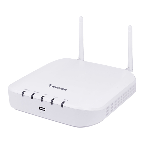
Page 8: Physical Description
1 LAN and PoE activity LED: Please refer to page 28 for LED definitions. 2 USB 2.0 port Rear View The difference between the ND8212W and ND8312 is the antenna. The ND8312 comes without the antenna. 1 Antenna connector... -
Page 9: Hardware Installation
It is important to leave a clearance of 10cm around the chassis. The clearance is required to ensure an adequate airflow through the chassis to ventilate heat. To ensure normal operation, maintain ambient airflow. Do not block the airflow around chassis such as placing the system in a closed cabinet. - Page 10 2. Secure the HDD brackets to the hard drive. 3. Connect SATA data and the SATA power cables to the hard drive. ...
- Page 11 4. Secure the hard drive to the mounting positions in the chassis with its label side facing up, and the connectors facing the right hand side of the chassis. 5. When done, install the top cover. ...
- Page 12 6. Install the included wireless antennas. (ND8212W) 7. Connect a mouse and/or keyboard to the USB connectors. If you prefer to hang the NVR on wall, drill and install two screws 104mm apart. ...
-
Page 13: Interface Connections
3. Connect USB devices such as mouse, keyboard, or USB thumb drive (formatted in FAT format), or UPS. 4. Connect the power adaptor to the power mains and the system. The NVR works with both wired and wireless cameras. The ND8312 comes without the wireless connectivity. -
Page 14: Initial Configuration - Via A Local Console
Pressing the Reset button for longer than 10 seconds will restore the factory defaults. Initial Configuration - via a Local Console A local console requires the following: 1. A monitor is connected via an HDMI cable. 2. A mouse and/or a keyboard are connected to the system. 3. - Page 15 Click the Apply button when the new password is accepted. 2. Select the UI language, Time zone, and current date and time. Click on the Continue button to proceed. ...
- Page 16 IMPORTANT: Except in the initial setup, changing system time can produce disruptions to the existing recordings. Turning the current system time back to a time when video recording was taking place can generate duplicate files. And those files may not be playable.
- Page 17 6. An optional utility, VIVOCloud, is available through the Apple and Android App Stores. The VIVOCloud works with a server hosted by VIVOTEK for bridging and tunneling video requests between client devices and network cameras/CMS/NVR. The utility simplifies and facilitates network configuration for access across the Internet.
- Page 18 To connect the NVR from a cell phone using the VIVOCloud: 6‐1. Click on the VIVOCloud button on the wizard. 6-2. The QR code will be generated. 6-3. Open the utility from your cell phone. If you already registered an account, tap LOG IN. If not, tap SIGN UP to register an account from a VIVOTEK server.
- Page 19 6-4. You can be defaulted to the Live view page. Tap the Add button below to add devices.
- Page 20 6-5. Tap the ADD DEVICES MANUALLY button. 6-6. You can then point your cell phone lens at the NVR screen (Step 5-3.) and use the SCAN QR CODES function to establish the connection. You may...
- Page 21 also manually enter the device ID. 6-7. The process will take several seconds to complete. 6-8. The NVR and the cameras under it will be ready for access.
- Page 22 7. Click the Done button. The LiveClient screen will display, and, by default, the recording from the selected cameras will immediately take place. ...
-
Page 23: Initial Configuration - Wireless Connection (Nd8212W)
Initial Configuration - Wireless Connection (ND8212W) 1. Press the WPS button on wireless camera for 3 to 5 seconds. Refer to VIVOTEK cameras’ Installation Guide for wireless connection details. 2. Press the WPS button on the NVR for less than 10 seconds. Wait for the system status LED to change to green. - Page 24 IMPORTANT: If you are not connecting your wireless cameras using the WPS function, ready the following: When the wireless NVR is operating in the AP mode, the default SSID and password is VVTK-XXXXXX/VVTK-XXXXXX. The six digits are the the last six digits of the MAC address on the NVR's product label.
-
Page 25: Initial Configuration - Via A Web Console (Optional)
Follow the onscreen instructions to complete the installation. 3. Start the Shepherd utility. The Shepherd utility will discover the NVR located in the same subnet. 4. Double-click on the ND8312 or ND8212W entry to start a web session with the NVR system. ... - Page 26 5. If you have configured a user name and password on the local console, use them to log in. Ideally, the initial configuration is performed via the local console. Expand the menu on the right of the Login button. Select and click on the Settings button to begin your configuration.
- Page 27 If you have let the setup wizard create single a disk volume, you can manually delete them and then create new volumes. Note that previous recordings will be erased. 8. Refer to the later discussions for the rest of the configuration procedure. LED Indicators ND8312 ND8212W ...
- Page 28 ND8312 Name Behavior Definitions Powered down. 1. Power Solid Green Device is up and running. Green solid System is ready. 2. Status Blinking every 1 Firmware or device pack is being second updated. Solid * Disk errors detected via S.M.A.R.T.
-
Page 29: Power Up And Power Down
* Configured disk drive is missing ( the buzzer will be sounded until it is manually disabled.) The Ethernet port is disconnected. 3. NET Orange blinking Data is being transmitted and received. Solid Green Working in the AP mode. 4. Wi-Fi Solid Orange Working in the Station mode, and... - Page 30 HDD component failures, and so on. Therefore, it is highly recommended to regularly back up your data, and VIVOTEK disclaims responsibilities of data loss or recovery. 2. Always power off the system using the software power button. Do not disconnect the power cord while the system is still operating.
-
Page 31: Introduction To The Local Console Interface
Introduction to the Local Console Interface By default, a live view appears on an HDMI monitor. The interface architecture of the local console is illustrated as follows: ... -
Page 32: How To Begin
IMPORTANT: Due to the limitation of system resources, the fisheye dewarp (1R & 1P modes) can only take place on one view cell, for one fisheye camera. 2-1. How to Begin 1. How to access the Configuration Portal? Make sure a mouse is attached to your NVR. Move your mouse cursor, and the Configuration Portal will appear on screen. - Page 33 This portal appears with a camera that does not support mechanical PTZ Tips: Here are some operation steps using the tool bar: 1. Single-click to select a view cell and bring out the tool bar. 2. Double-click to expand a view cell to the full view. 3.
- Page 34 PTZ control panel for ordinary PTZ type PTZ control panel for joystick type PTZ ...
- Page 35 3. How to retrieve and access recorded videos? 3-1. One is to access the video clips taken within 1 hour. Left-click to select a view cell, and then click on the Recording clips button. Select a time value by a single click. You will be prompted for User name and Password, enter admin and admin (the default user name and password), and then click Login.
- Page 36 3-2. Another way to access past recorded videos is to open the Search recording clips window. Move your mouse cursor to display the Configuration Portal (without selecting any view cell). Click on the Search recording clips button. Please refer to page 47 for more information about the search functions.
- Page 37 5. Why live view is unavailable? The default live view receives a camera's stream #1. If a camera's stream #1 is configured using MPEG-4 as the video codec, the following message will prompt. You can go to the Settings > Camera > Media > Video window to configure the video codec of stream #1 into H.264. The same will occur if you connect some newer VIVOTEK 9xxx series H.265 models. You will then need to chanage the CH1 and CH2 ...
- Page 38 video streams to H.264. 6. How do I move to another layout page? Move your cursor to the right hand side of your screen. The page turner buttons will appear as shown below. For example, if you have 8 cameras placed on 2 2x2 layout pages, use these buttons to visit different pages.
-
Page 39: Operation On A Camera View Cell
7. Why the onscreen tool bars disappear after some time? The system comes with idle modes. Below are the applicable conditions: 1. Live view: if no management activities occur for 5 seconds, the tool bars disappear from screen. When in the idle mode, mouse cursor and tool bars will disappear. - Page 40 1. PTZ control: Click and drag the nudget in the center towards the direction you wish to move to. 2. Focus: Click on the Focus near and Focus far buttons to adjust camera focus. 3. Home: Click to move the camera lens towards the default home position. 4.
- Page 41 Below is the PTZ panel that appears with ordinary PTZ cameras 1. PTZ control: Click on the arrow buttons to move towards the direction you wish to move to. 2. Focus: Click on the Focus near and Focus far buttons to adjust camera focus.
- Page 42 This portal appears with a fisheye camera. The PiP and PTZ buttons will then be disabled for a fisheye camera. 2-2-2. Digital Zoom Panel Digital zoom is a function that allows an operator to zoom in or zoom out on a live video.
-
Page 43: Play Recording Clips Panel
2-2-3. Play Recording Clips Panel The Play Recording Clips function provides a shortcut to the latest recordings on the system. You can select 30 secs, 1 min, 3 mins, 10 mins, and 60 mins for an immediate playback. For security reasons, using this function requires users to enter his/her credentials. - Page 44 2-2-4. DI/DO The DI/DO panel provides a glimpse of all DI and DO signal statuses from the connected cameras. You can manually trigger a digital output by clicking on its indicators. When a digital input is triggered, its status will also be indicated on the panel. WARNING: Please note that DO is triggered by one click. You should then click again to disable ...
- Page 45 2-2-6. Right-click Commands Left-click to select a camera. Right-click to display the selection menu. 1. Camera information: Click to display camera name, resolution, codec, or frame rate on the view cell. The information will display on the upper left corner of a view cell.
- Page 46 ...