Makita HR4000C Technical Information
40mm rotary hammer
Hide thumbs
Also See for HR4000C:
- Instruction manual (25 pages) ,
- Parts breakdown (4 pages) ,
- Instruction manual (21 pages)
Table of Contents
Advertisement
Quick Links
T
ECHNICAL INFORMATION
Models No.
Description
C
ONCEPTION AND MAIN APPLICATIONS
Model HR4000C accept SDS-max shank bit and overcomes competitors'
models.
Its brief benefits are;
*Less operator's fatigue than HILTI TE55
less vibration and reaction toward hands
better feeling at drilling and hammering
More efficiency than HILTI TE55
Drilling
:10%up
Hammering:20%up
*Electronical speed control features
. Variable speed control
. Soft start
. Steady speed
SPECIFICATIONS
Voltage(V)
100
120
220
230
240
No load speed
Bit-type
Drilling capacities
Net weight
Cord length
STANDARD EQUIPMENT
Depth Gauge--------------------------------1pc.
Grease Vessel(Bit Grease)----------------1pc.
Plastic Carrying Case ---------------------1pc.
Grip 36 Ass'y-------------------------------1pc.
Side Handle Ass'y--------------------------1pc.
OPTINAL ACCESSORIES
Tungsten-carbite tipped bit
Bit diameter : 10mm(3/8"),10.5mm(7/16"),11mm(7/16"),12mm(1/2"),12.5mm(1/2"),12.7mm(1/2"),
13.5mm(1/2"),14.3mm(9/16"),14.5mm(9/16"),16mm(5/8"),17mm(11/16"),17.5mm(11/16"),
18mm(11/16"),19mm(3/4"),20mm(13/16"),21.5mm(7/8"),22mm(7/8"),25mm(1"),
28mm(1-1/8"),32mm(1-1/4"),35mm(1-3/8"),38mm(1-1/2")
Bull Point, Cold Chisel, Tile Chisel
Scaling Chisel, Clay Spade
Core Bit adapter, Grase Vessel(Hammer greese)
FEATURES AND BENEFITS
1. Double insulated
2. See the sheets attached for more information.
The standard equipment for the tools shown may differ from country to country.
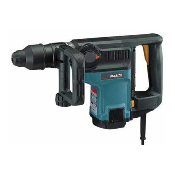
HR4000C
40mm Rotary Hammer
Current(A)
Cycle(Hz)
11.0
50/60
9.6
50/60
5.0
50/60
4.8
50/60
4.6
50/60
Revolutions per minute
Blows per minute
Tungsten-carbitde
tipped bit
Core bit
Continuous Rating(W)
Input
Output
1050
330
1050
330
1050
330
1050
330
1050
330
230
450rpm
1250
2500bpm
SDS-max shank bit
Diameter of shank : 180 mm(11/16'')
T.C.T. bit:40mm(1-9/16")
105 mm(4-1/8")
6.2Kg(13.6lbs)
5m(16.4ft)
New Tool
100 (3-15/16")
455
(17-7/8")
Max.Output(W)
850
850
850
850
850
253(10")
Advertisement
Table of Contents

Related Manuals for Makita HR4000C


Summary of Contents for Makita HR4000C
- Page 1 Models No. HR4000C Description 40mm Rotary Hammer 100 (3-15/16") ONCEPTION AND MAIN APPLICATIONS Model HR4000C accept SDS-max shank bit and overcomes competitors' (17-7/8") models. Its brief benefits are; *Less operator's fatigue than HILTI TE55 less vibration and reaction toward hands 253(10")
- Page 2 Torque of fastening screw 60-100kgf.cm crank cap----crabk housing (4.3-7.2ft.lbs) Circuit diagram Brush holder Black White Connector Switch at closed end Violet power supply cord Field Orange color Controller Black Orange color White Brush holder Connector at closed end...
- Page 3 3)How to replace the armature c. Remove the hexagon-holed bolt and then remove the a. Lower the chuck cover and remove the tool handle.(See the figure 5.) holder cap.(See the figure 4.) d. Remove the connector white and black. b. Remove the pan head screw, and then remove the crank (See the figure 5.) housing cover and gear housing cover.(See the figure 4.) Tool holder cap...
- Page 4 4)Disassembling the chuck(See the figure 9.) a. As mentioned in 3)-a How to replace the armature, remove the tool holder cap, the chuck cover and the crank housing cover. b. Remove the ring spring 25. c. Remove the reaf spring 25 for the step pin 8 . d.
- Page 5 8)Assembling the piston rod and crank shaft(See the figure 13.) a. Set the 2 pieces of O ring 30 on the cylinder 28.5, and insert them into the crank housing. b. Insert the piston until the rod hole is placed inside the crank room. c.
- Page 6 10)Assembling the tool holder a. Set the parts described below into the crank housing.(See the figure 15.) b. To set the straight bevel gear 33, use the tool holder for smooth setting.(See the figure 16.) Crank housing Straight bevel Compression Rubber ring 17 Slide sleeve gear 33...
- Page 7 11)Assembling the torque limiter a. Assemble the ball bearing 1207, flat washer 12(Outer dia. 24 mm) and torque limiter complete into the spiral bevel gear 10. (See the figure 20.) Flat washer 12 Note ) Use care not to miss the pin 4 for preventing Groove of the change key (Outer dia.
- Page 8 (Page 13 of 14) 15)Applying positions for grease To prevent abrasion and overheating at earlier stage, please apply the MAKITA grease R No.00 at the positions shown below. a. O ring of striker b. Inner portion of ring 45 c. Inner portion of slide sleeve d.
-
Page 9: Circuit Diagram
Circuit diagram Brush holder Black White Connector Switch at closed end Violet Field Orange color Cab tire cord Controller Black Orange color White Brush holder Connector at closed end...