
Related Manuals for Panasonic MDF-594


Summary of Contents for Panasonic MDF-594
-
Page 1: Operating Instructions
Operating Instructions Ultra-Low Temperature Freezer MDF-594AT Please read these instructions carefully before using this product, and save this operating instructions for future use. See page 32 for all Model Numbers. -
Page 2: Table Of Contents
CONTENTS INTRODUCTION P. 2 PRECAUTIONS FOR SAFE OPERATION P. 3 ENVIRONMENTAL CONDITIONS P. 7 FREEZER COMPONENTS P. 8 Control panel P. 10 INSTALLATION SITE P. 11 INSTALLATION P. 12 START-UP OF UNIT P. 13 CHAMBER TEMPERATURE SETTING P. 14 ALARM TEMPERATURE SETTING P. -
Page 3: Introduction
INTRODUCTION Read this operating instructions carefully before using the appliance and follow the instructions for safety operation. Our company never guarantee any safety if the appliance is used for any objects other than intended use or used by any procedures other than those mentioned in this operating instructions. Keep this operating instructions in an adequate place to refer to it as necessary. -
Page 4: Precautions For Safe Operation
PRECAUTIONS FOR SAFE OPERATION It is imperative that the user complies with this operating instructions as it contains important safety advice. Items and procedures are described so that you can use this unit correctly and safely. If the precautions advised are followed, this will prevent possible injury to the user and any other person. - Page 5 PRECAUTIONS FOR SAFE OPERATION WARNING Do not use the unit outdoors. Current leakage or electric shock may result if the unit is exposed to rain water. Only qualified engineers or service personnel should install the unit. The installation by unqualified personnel may cause electric shock or fire. Install the unit on a sturdy floor and take an adequate precaution to prevent the unit from turning over.
- Page 6 PRECAUTIONS FOR SAFE OPERATION WARNING Ensure you do not inhale or consume medication or aerosols from around the unit at the time of maintenance. These may be harmful to your health. Never splash water directly onto the unit as this may cause electric shock or short circuit. Never put containers with liquid on the unit as this may cause electric shock or short circuit when the liquid is spilled.
- Page 7 PRECAUTIONS FOR SAFE OPERATION CAUTION Use a dedicated power source (a dedicated circuit with a breaker) as indicated on the rating label attached to the unit. A branched circuit may cause fire resulting from abnormal heating. Connect the power supply plug to the power source firmly after removing the dust on the plug. A dusty plug or improper insertion may cause a heat or ignition.
-
Page 8: Environmental Conditions
ENVIRONMENTAL CONDITIONS This equipment is designed to be safe at least under the following conditions (based on the IEC61010-1): Indoor use; Altitude up to 2000 m; Ambient temperature 5 C to 40 Maximum relative humidity 80% for temperature up to 31 C decreasing linearly to 50% relative humidity at 40 Mains supply voltage fluctuations up to ±10% of the nominal voltage;... -
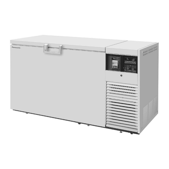
Page 9: Freezer Components
FREEZER COMPONENTS MDF-594... - Page 10 FREEZER COMPONENTS 1. Lock 2. Door: Hinged type. The door can be opened in any angle on the way to full open. 3. Magnetic door gasket: Seals the door and prevents leakage of cold air. 4. Inner lid: Serves as a means of reducing cold air leakage when the door is open. Remove the frost before it is accumulated too much.
-
Page 11: Control Panel
FREEZER COMPONENTS Control panel 12 11 MDF-594AT/ 794AT 1. Power switch (POWER): Power all functions except remote alarm and Backup cooling kit for AT type. 2. CO Backup switch (CO BACK UP): AT type only. 3. CO Backup test switch (TEST): AT type only. 4. -
Page 12: Installation Site
INSTALLATION SITE To operate this unit properly and to obtain maximum performance, install the unit in a location with the following conditions: A location not subjected to direct sunlight Do not install the unit under direct sunlight. Installation in a location subjected to direct sunlight cannot obtain the intended performance. -
Page 13: Installation
Ensure the unit is level. MDF-594 Leveling foot 3. Fixing the unit Two fixtures are attached to the rear of the frame. Fix the frame to the wall with these fixtures and rope or chain. -
Page 14: Start-Up Of Unit
START-UP OF UNIT Follow the procedures for the initial and consequent operations of the unit. 1. Make sure that all the switches on the control panel, such as the power switch, battery switch, CO backup switch (AT type only) are off. 2. -
Page 15: Chamber Temperature Setting
CHAMBER TEMPERATURE SETTING Table 1 shows the basic operation method. Perform key operations in the sequence indicated in the table. The example in the table is based on the assumption that the temperature is -75 Note: The unit is set at the factory that the chamber temperature is -80 Table 1. -
Page 16: Alarm Temperature Setting
ALARM TEMPERATURE SETTING This unit is provided with the high temperature alarm. The setting of high temperature alarm is 10 C or C (The setting value is 2 kinds.) higher than the setting of chamber temperature. The procedure in table 2 shows the sequence to set the high temperature alarm at 15 C higher than the setting of chamber temperature. -
Page 17: Setting Of Alarm Resume Time
SETTING OF ALARM RESUME TIME The alarm buzzer is silenced by pressing alarm buzzer stop key (BUZZER) on the control panel during alarm. The buzzer will be activated again after certain suspension if the alarm condition is continued. The suspension time can be set by following the procedure shown in the table 3 below. The example in the table is based on the assumption that the desired duration is 20 minutes. -
Page 18: Remote Alarm Terminal
REMOTE ALARM TERMINAL The terminal of the remote alarm is installed at the back of the unit. The signal is contact output. The contact capacity is 2 A (DC 30 V) . a) Contact output : normal open connect with N.O. and COM. b) Contact output : normal close connect with N.C. - Page 19 ALARMS AND SAFETY FUNCTIONS Table 4. Alarm and safety function Alarm & safety Situation Indication Buzzer Safety operation Alarm lamp blinks. If the thermal sensor is E01 and 50 C is disconnected. Remote alarm displayed alternately. Intermittent Continuous tone Alarm lamp blinks. If the thermal sensor is operation E02 and -170...
-
Page 20: Temperature Recorder (At Type)
TEMPERATURE RECORDER (AT type) The figure below shows the description of a temperature recorder. The temperature recorder is provided with model AT type. Time Temperature Warning indicator Recording indicator Pen holder lever Door Cartridge Feeding of chart 1. Open the door and let down the lever of the penholder; the pen point is apart from the chart. (Fig. 1) 2. - Page 21 TEMPERATURE RECORDER (AT type) Setting of backup temperature 1. There is a red guide on the top of the temperature displayer. Adjust the guide with your finger to backup temperature, at which temperature the auxiliary cooling system starts to operate. 2.
-
Page 22: Backup Cooling Kit (At Type)
BACKUP COOLING KIT (AT type) WARNING As with any equipment that uses CO gas, there is a likelihood of oxygen depletion in the vicinity of the equipment. It is important that you assess the work site to endure there is suitable and sufficient ventilation. -
Page 23: Routine Maintenance
ROUTINE MAINTENANCE WARNING Always disconnect the power supply to the unit prior to any repair or maintenance of the unit in order to prevent electric shock or injury. Ensure you do not inhale or consume medication or aerosols from around the unit at the time of maintenance. -
Page 24: Troubleshooting
TROUBLESHOOTING If the unit malfunctions, check out the following before calling for service. Malfunction Check/Remedy The circuit breaker of power source is active. The chamber is not cooled The voltage is too low. In this case, call an electrician. at all The power switch is not ON. -
Page 25: Disposal Of Unit
DISPOSAL OF UNIT WARNING If the unit is to be stored unused in an unsupervised area for an extended period ensure that children do not have access and doors cannot be closed completely. The disposal of the unit should be accomplished by appropriate personnel. Always remove doors to prevent accidents such as suffocation. - Page 26 The symbol mark and recycling systems described below apply to EU countries and do not apply to countries in other areas of the world. Your Panasonic product is designed and manufactured with high quality materials and components which can be recycled and/or reused.
- Page 27 POUR LES UTILISATEURS DE UE Le symbole et les systèmes de recyclage évoqués ci-dessous s'appliquent uniquement aux pays de UE. Votre produit Panasonic est conçu et fabriqué avec des composants et des matériaux de hautes qualités qui peuvent être recyclés et/ou réutilisés.
- Page 28 O símbolo e os sistemas de reciclagem descritos abaixo aplicam-se aos países da UE e não se aplicam aos países noutras áreas do mundo. O seu produto Panasonic foi concebido e fabricado com materiais e componentes de elevada qualidade que podem ser reciclados e/ou reutilizados.
- Page 29 Het symbool en de recycleersystemen die hieronder beschreven worden, zijn van toepassing op de landen in de EU en zijn niet van toepassing op landen in andere delen van de wereld. Uw Panasonic product is ontworpen en gemaakt met materialen en onderdelen van hoge kwaliteit, die gerecycleerd en opnieuw gebruikt kunnen worden.
-
Page 30: Disposal Of Battery
DISPOSAL OF BATTERY The battery for power failure alarm is an article for consumption. The battery life is approximately 3 years. The buzzer and alarm lamp cannot be activated at the power failure and the stored items may be influenced if the battery is left as it is for more than 3 years. It is recommended that the battery is replaced ahead of time. -
Page 31: Specifications
SPECIFICATIONS Product name Ultra-Low Temperature Freezer Ultra-Low Temperature Freezer MDF-594 MDF-594AT External dimensions W2010 mm x D770 mm x H1070 mm Internal dimensions W1280 mm x D500 mm x H762 mm Effective capacity 487 L Exterior Painted steel Interior Stainless steel... - Page 32 SPECIFICATIONS Product name Ultra-Low Temperature Freezer Ultra-Low Temperature Freezer MDF-794 MDF-794AT External dimensions W2570 mm x D770 mm x H1070 mm Internal dimensions W1840 mm x D500 mm x H762 mm Effective capacity 701 L Exterior Painted steel Interior Stainless steel Door Painted steel Insulation...
-
Page 33: Performance
PERFORMANCE Product name Ultra-Low Temperature Freezer MDF-594/ MDF-594AT Model No. MDF-594-PB MDF-594-PA MDF-594-PE MDF-594AT-PB MDF-594-PK MDF-594AT-PE Cooling performance Center part of freezing room; -86 C (Ambient temperature; +30 C, no load) Temperature Control range C to -86 Power voltage AC 220 V... -
Page 34: Safety Check Sheet
CAUTION Please fill in this form before servicing. Hand over this form to the service engineer to keep for his and your safety. Safety check sheet 1. Freezer contents : □Yes □No Risk of infection: □Yes □No Risk of toxicity: □Yes □No Risk from radioactive sources:... - Page 35 1-1-1 Sakata, Oizumi-Machi, Ora-Gun, Gunma 370-0596 Japan Printed in Japan 7FB6P151474001 © Panasonic Healthcare Co., Ltd. 2012 S0412-10412...