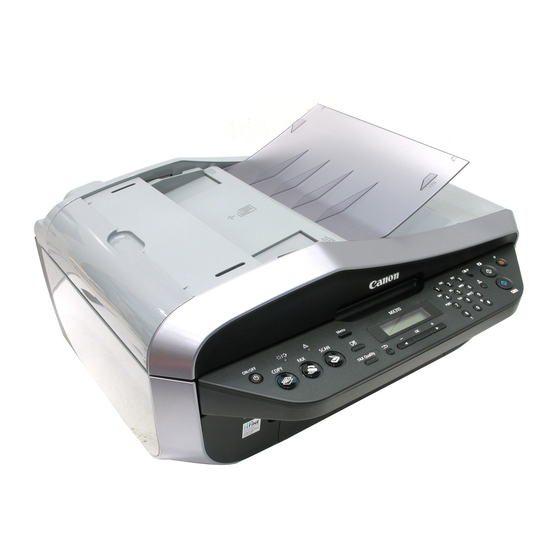
Canon PIXMA MX310 Service Manual
Hide thumbs
Also See for PIXMA MX310:
- Quick start manual (131 pages) ,
- Setup instructions (2 pages) ,
- Brochure (2 pages)
Table of Contents
Advertisement
Advertisement
Table of Contents

Related Manuals for Canon PIXMA MX310


Summary of Contents for Canon PIXMA MX310
-
Page 1: Service Manual
PIXMA MX310 SERVICE MANUAL Canon Copyright 2007, Canon U.S.A. This technical publication is the proprietary and confidential information of Canon U.S.A. which shall be retained for reference purposes by Authorized Service Facilities of Canon U.S.A. Its unauthorized use is prohibited. -
Page 2: Table Of Contents
TABLE OF CONTENTS 1. LIST OF ERROR DISPLAY / TROUBLESHOOTING 1-1. Operator Call Errors 1-2. Service Call Error (Cyclic Blinking in Orange (Alarm LED) and Green (ON/OFF LED)) 1-3. Fax Errors 2. ADJUSTMENT / SETTINGS 2-1. Service Mode 2-2. PTT Parameter Mode 2-3. -
Page 3: List Of Error Display / Troubleshooting
1. LIST OF ERROR DISPLAY / TROUBLESHOOTING 1-1. Operator Call Errors Errors and warnings are displayed by the following ways: 1. Operator call errors are indicated by the Alarm LED lit in orange, and the error and its solution are displayed on the LCD. - Page 4 The remaining ink [1686] U162 CHECK INK Replace the ink cartridge and amount unknown. U162 close the scanning unit. Printing with an empty ink cartridge can damage the machine. To continue printing without replacing the ink cartridge(s), press the Stop/Reset button for 5 sec.
-
Page 5: Service Call Error (Cyclic Blinking In Orange (Alarm Led) And Green (On/Off Led))
1-2. Service Call Error (Cyclic Blinking in Orange (Alarm LED) and Green (ON/OFF LED)) Cycles of Corrective action blinking in Error Error Conditions (Replacement of listed parts, orange and Code which are likely to be faulty) green 2 times Carriage error [5100] An error occurred in the carriage - Carriage unit... -
Page 6: Fax Errors
1-3. Fax Errors For error other than those listed below, please refer to the “G3/G4 Facsimile Error Code List (Revision 2) HY8-23A0-020.” (1) User error codes Error code TX / RX Meaning #001 Document jam #003 TX / RX Document is too long, or page time-over #005 TX / RX Initial identification (T0 / T1) time-over... - Page 7 ##220 TX / RX System error (main program hang-up) ##224 TX / RX An error has occurred in the procedure signal in G3 transmission. ##226 TX / RX The stack pointer has shifted from the RAM area. ##229 The recording area has been locked for 1 minute. ##232 The encoder control unit has malfunctioned.
- Page 8 the control channel or further, causing T1 time-over ##750 After transmitting PPS-NULL in ECM transmission, no significant signal has been received, and re-transmission of the procedure signal has been attempted the number of specified times but failed. ##752 After transmitting PPS-NULL in ECM transmission, DCN has been received.
- Page 9 the procedure signal has been attempted the number of specified times but failed, or T5 time-over (60 sec.) has occurred. ##769 After transmitting PPS-EOP in ECM transmission, re-transmission of the procedure signal has been attempted the number of specified times but failed. ##770 After transmitting EOR-NULL in ECM transmission, no significant signal has been received, and re-transmission of the procedure...
- Page 10 ##788 After transmitting EOR-EOP in ECM transmission, re-transmission of the procedure signal has been attempted the number of specified times but failed, or T5 time-over (60 sec.) has occurred. ##789 After transmitting EOR-EOP in ECM transmission, ERR has been received. ##790 After receiving EOR-EOP in ECM reception, ERR has been transmitted.
-
Page 11: Adjustment / Settings
2. ADJUSTMENT / SETTINGS 2-1. Service Mode <Service mode operation procedures> 1) With the machine power turned off, while pressing the Stop/Reset button, press and hold the ON/OFF button. (DO NOT release the buttons). The Power LED lights in green to indicate that a function is selectable. - Page 12 4 times Green (Power) Ink absorber counter Set a sheet of A4 or Letter sized plain paper in resetting the rear tray and reset the ink absorber counter. After the ink absorber counter is reset, the counter value is printed automatically. See "Ink absorber counter resetting"...
- Page 13 Time(s) Ink absorber 0 times Main ink absorber (0%) 1 time Platen ink absorber (0%) 2 times Both the main and platen ink absorbers (0%) 3 times or more Press the ON/OFF button to return to the ink amount resetting mode. 3) Press the ON/OFF button to specify the ink absorber whose value should be reset to 0%.
- Page 14 <Button and LCD test> Confirm the operation after replacement of the operation panel unit, scanner unit, or Logic board. 1) In the service mode, after pressing the Stop/Reset button 12 times, press the ON/OFF button to enter the button and LCD test mode. The ON/OFF button LED: Lights in green In Use/Memory LED: Lights in green...
- Page 15 Button name ON/OFF COPY SCAN Menu Settings FAX Quality Back Redial/Pause Coded Dial Black Start Color Start Stop/Reset Note: There is no buttons corresponding to the number 29-40. Accordingly, after pressing all 28 buttons, the segments of the number 29-40 become undisplayed automatically and nothing is displayed on the LCD.
- Page 16 2 times: Kana font 5) Press the Stop/Reset button to return to the menu selection of the service mode (Service Model Idle). <Ink absorber counter setting> Set the ink absorber counter value to a new EEPROM after the logic board is replaced in servicing. 1) Before replacement of the logic board, check the ink absorber counter value in EEPROM information print.
-
Page 17: Ptt Parameter Mode
5 times 6 times 7 times 8 times 9 times Not valid. 10 times or more Press the ON/OFF button to return to the ink absorber counter setting mode. 6) Press the ON/OFF button to set the selected value to the EEPROM. Print EEPROM information to confirm that the value is properly set to the EEPROM. - Page 18 NU MERIC PARAM. menu PTT PARAMETER #3 FAX TYPE Note: Not used in servicing. PTT PARAMETER #4 NCU Note: Not used in servicing. PTT PARAMETER #5 PTT SPECIAL Note: Not used in servicing. PTT PARAMETER #6 FAX TEST Note: Not used in servicing. 4.
- Page 19 English: QY8-13BC-010 Japanese: QY8-12B6-020 4. After finalizing the setting value of each bit of the SW#, press the Stop/Reset button. 5. Press the ON/OFF button. 2-2-4) #2 NUMERIC PARAM. 1. After entering the #2 NUMERIC PARAM. menu, the following screen will be displayed. #2 NUMERIC PAEAM.
- Page 20 PTT PARAMETER output sample for the MX310 US model (20/32)
-
Page 21: User Mode
2-3. User Mode Function Procedures Remarks Nozzle check pattern Perform via the machine operation Set a sheet of plain paper (A4 or printing panel, or from the MP driver Letter) in the rear tray. Maintenance tab. Print head cleaning Perform via the machine operation Unclogging of the print head panel, or from the MP driver nozzles, and maintenance to keep... -
Page 22: Notes On Service Part Disassembling / Reassembling
2-4. Notes on Service Part Disassembling / Reassembling (1) Paper feed motor attachment position adjustment When attaching the paper feed motor, the following adjustment will be needed. 1) When removing the screws, make marks where the screws are. 2) When attaching the motor, fasten the screws to each marked position. 3) After replacement, be sure to perform the service test print, and confirm that no strange noise or faulty print operation (due to dislocation of the belt or gear, or out-of-phase motor, etc.) occurs. - Page 23 <Test procedure> Set the paper thickness lever to the left (normal position) and print images on the PR paper, then confirm that print result has no problem and that the print head does not contact paper. If print quality deterioration or print head contact is found, adjust the head-to-paper distance with the following procedures.
-
Page 24: Grease Application
2-5. Grease Application Where to apply grease / Grease oil amount (mg) Floil KG-107A Printer Chassis QY9-0057-000 Entire rear surface of the upper bent part: 180±20mg (160 to 200mg) Entire rear surface of the bottom front bent part + entire upper surface of the bottom part: 600±60mg (... -
Page 25: Notes On Machine Transportation
2-6. Notes on Machine Transportation Be sure to transport the machine after moving the CIS unit (Scanner Carriage Unit) to the appropriate position. If the machine whose CIS unit is in the home position (inappropriate position) is vibrated or dropped when it is transported, the scanner flat cable may be jammed/damaged and the scanner may become out of work.