Krell Industries EVOLUTION Evolution 202 Owner's Reference Manual
Krell industries owner's manual stereo preamplifier evolution 202
Hide thumbs
Also See for EVOLUTION Evolution 202:
- Brochure (1 page) ,
- Owner's reference manual (48 pages) ,
- Quick setup manual (2 pages)

Related Manuals for Krell Industries EVOLUTION Evolution 202


Summary of Contents for Krell Industries EVOLUTION Evolution 202
- Page 1 EVOLUTION E V O L U T I O N 2 0 2 S T E R E O P R E A M P L I F I E R O W N E R ’ S R E F E R E N C E THE LEADER IN AUDIO ENGINEERING...
-
Page 2: Important Safety Instructions
Inc. All other trademarks are registered to their respective companies. © 2006 by Krell Industries, Inc. All rights reserved ® is a registered trademark of Krell Industries, Inc., and is restricted for use by ™ is a trademark of Krell Industries, Inc. and is a Krell technology ™, Evolution... -
Page 3: Table Of Contents
Contents List of Illustrations, page 4 A Letter from Dan D’Agostino, page 5 SECTION ONE: Evolution 202 Features and Technology, page 6 Features, Revolutionary Krell CAST Technology, Definition of Terms SECTION TWO: Unpacking and Placement, page 11 Opening the Evolution 202 Shipping Carton SECTION THREE: Quick Start, page 13 Connecting the Evolution 202 to Your System, Operating the Evolution 202... -
Page 4: List Of Illustrations
List of Illustrations Figure 1, page 15 Evolution 202 Preamplifier and Power Supply Front Panels Inset Preamplifier and Power Supply Stacked View Figure 2, page 19 Evolution 202 Remote Control Figure 3, page 22 Evolution 202 Preamplifier and Power Supply Back Panels... -
Page 5: A Letter From Dan D'agostino
A Letter from Dan D’Agostino Dear Audio Enthusiast, Thank you for your purchase of the Krell Evolution 202 preamplifier. The preamplifier plays a vital role in audio playback by mediating the line-level out- put of a wide variety of source components in preparation for the amplifier’s input. At no other point in the reproduction process is music so vulnerable to change, as the signal level is small, and susceptible to noise and distortion. - Page 6 SECTION Evolution 202 Features and Technology This section describes the innovative features and technology of the Evolution 202 preamplifier, and defines CAST and other key terms used in this reference. The Evolution 202 Stereo Preamplifier, evolving from the flagship Evolution Two, works to carefully transmit audio signals without damaging the ephemeral staging and dimensional components of the music.
-
Page 7: Revolutionary Krell Cast Technology
In stand-by mode, all the analog circuitry continues to operate at the same bias current; however, the main analog supply voltages decrease by 30 percent. The result is a corresponding 30 percent reduction in power consumption and heat without the need to wait for the electronics to “warm up” before listening. Revolutionary Krell CAST Technology Current Audio Signal Transmission, termed CAST, is a revolutionary method of connecting analog audio components for unparalleled sonic performance. -
Page 8: Section One: Evolution 202 Features And Technology
(SECTION ONE: Evolution 202 Features and Technology continued) Krell Current Mode maintains the integrity of the signal within the component and CAST preserves the transmitted signal between components. Together, CAST and Krell Current Mode technologies unify separate Krell components into a single global circuit. -
Page 9: Definition Of Terms
Definition of Terms The following are definitions of key terms used in this owner’s reference: Inputs and Outputs Balanced A symmetrical input or output circuit that has equal impedance from both input terminals to a common ground reference point. The industry standard for profes- sional and sound recording installations, balanced connections have 6 dB more gain than single-ended connections and allow the use of long interconnect cables. - Page 10 (SECTION ONE: Definition of Terms continued) Technology Krell Current Mode A proprietary Krell circuit topology in which the audio gain stages of a component operate in the current rather than voltage domain. This unique technology provides the component with exceptional speed, and a wide bandwidth.
-
Page 11: Opening The Evolution 202 Shipping Carton
SECTION Unpacking and Placement This section describes the procedures for safely unpacking and placing your Evolution 202 Preamplifier. The Evolution 202 preamplifier is shipped in 1 carton consisting of 2 chassis: 1 power supply chassis and 1 preamplifier chassis. Opening the Evolution 202 Shipping Carton The Evolution 202 shipping carton measures 22.3 in. - Page 12 (SECTION TWO: Unpacking and Placement continued) Placement Before you install an Evolution 202 preamplifier into your system, please follow the guidelines in this section to select a location for your component. This will facili- tate a clean, trouble-free installation. The Evolution 202 preamplifier does not require a special rack or cabinet for instal- lation.
-
Page 13: Quick Start
THREE SECTION Quick Start To access the full array of available functions for the Evolution 202, please read this entire owner’s reference manual. The abbreviated routine in this Quick Start section will allow you to connect and operate the Evolution 202 quickly and enjoy its basic functions. -
Page 14: Section Three: Quick Start
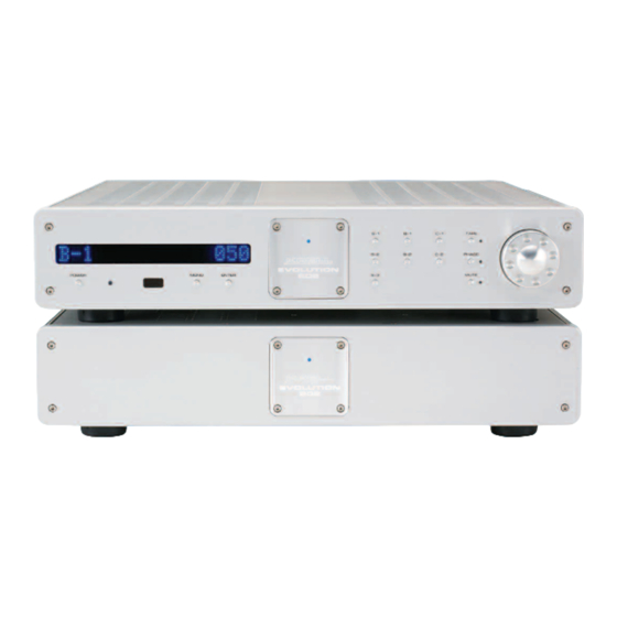
(SECTION THREE: Quick Start) Operating the Evolution 202 After the Evolution 202 is connected to your system and to AC power, and the front panel display has stopped scrolling, begin operation: Press the power button (1) on the front panel, or the remote control power key. The standby/power LED turns blue. - Page 15 FOUR SECTION Anatomy of the Evolution 202 This section describes the Evolution 202 Preamplifier functions. Figure 1 Evolution 202 Preamplifier and Power Supply Front Panels Power 1 Power Button 7 Stand-by/Power LED 2 Infrared Emitter Remote Functions 4 Infrared Sensor 3 Front Panel Display Display Navigate/...
- Page 16 (SECTION FOUR: Anatomy of an Evolution 202 continued) Front Panel Description See Figure 1 on the previous page The Evolution 202 Preamplifier is comprised of two chassis: the preamplifier chassis and the power supply chassis. Front panel functions are described below: Chassis Preamplifier Chassis...
- Page 17 Preamplifier Functions 8, 9, 10 Input Select Buttons or Keys Use these buttons to select the corresponding rear panel input that is connect- ed to a CAST (C-1, C-2), balanced (B-1, B-2), or single-ended (S-1, S-2, S-3) analog source. The front panel display shows the selected input and volume level.
-
Page 18: Level Control
(SECTION FOUR: Anatomy of an Evolution 202 continued) Level Control 14 Level Control Knob or Level Keys Use this knob or keys to increase or decrease system volume level or, with the balance key (C), to adjust balance. The level control knob or keys also select menu options that customize the Evolution 202. - Page 19 Figure 2 Evolution 202 Remote Control Power 1 Power Key Navigate/ 5 Menu Key Customize 6 Enter Key Input 8 Single-ended Input Selectors Selection Keys 9 Balanced Input Selection Keys 10 CAST Input Selection Keys 11 Tape Selection Key Mute 12 Mute Key Phase 13 Phase Key...
-
Page 20: Remote Control Description
(SECTION FOUR: Anatomy of an Evolution 202 continued) Remote Control Description See Figure 2 on the previous page The Evolution 202 remote provides the same power, preamplifier, level control, and navigate/customize functions as the preamplifier’s front panel. In addition, the remote has CD and DVD functions, and menu configuration functions. Keys Labled 1 to 14 These remote keys have the same function (and callout number) as the corresponding front panel controls described in the preceding pages. - Page 21 Balance Functions C Bal(ance) Keys Use these with the level keys (14) to adjust the left and right channel balance. Compact Disc and DVD Functions The compact disc and DVD dual-purpose keys of the remote control are function- al with all Krell compact disc and DVD players. H CD Key Use this to activate CD functions.
- Page 22 (SECTION FOUR: Anatomy of an Evolution 202 continued) Figure 3 Evolution 202 Preamplifier and Power Supply Back Panels Inputs 15 Balanced Inputs: B-1, B-2 16 Single-ended Inputs: S-1, S-2, S-3 17 Tape Input 18 CAST Inputs: C-1, C-2 Outputs 19 Tape Output 20 Main Outputs: Single-ended Main Output Balanced Main Output...
-
Page 23: Back Panel Description
Back Panel Description See Figure 3 on the previous page The preamplifier back panel provides all input and output connections, remote control inputs and outputs, and the power connection. Back panel features and their descriptions follow. Inputs 15 Balanced Inputs: B-1, B-2 These are balanced analog source inputs with XLR connectors. - Page 24 (SECTION FOUR: Anatomy of an Evolution 202 continued) Remote Connections on the Back Panel 22 RS-232 The RS-232 port receives messages from a computer-based control system, providing integrated control of all preamplifier functions. The RS-232 input uses a 9-pin D-subminiature connector. See the Evolution 202 developer's ref- erence, entitled RS-232 Port: Sending Commands and Interpreting Data, for more information.
- Page 25 Phono Stage Connector 28 Phono Power Port This port is used for connecting the preamplifier to a Krell KPE phono stage. Power 24 DC Power Connector This is used to connect the preamplifier chassis and the power supply chassis, using the provided 12-pin DC power cable. 26 Analog and Digital Power Supply Fuses Always unplug the power cord before inspecting these fuses.
-
Page 26: Connecting The Evolution 202 To Your System
FIVE SECTION Connecting the Evolution 202 to Your System This section describes Evolution 202 Preamplifier connections. Input and Output Connections Krell recommends using its proprietary Krell CAST system for unparalleled sonic performance for connections between the Evolution 202 preamplifier and other CAST-equipped components. -
Page 27: Connection Steps
Connection Steps Position the power supply and preamplifier where you intend to use them in your system. Do not move the connected chassis after they are assembled. The following steps describe how to connect an Evolution 202 preamplifier to your system: Connect the power supply chassis and preamplifier chassis with the 12-pin DC cable provided, using the DC power connectors (24) on the back panels. -
Page 28: On/Off And Stand-By Operation
SECTION Evolution 202 Operation The Evolution 202 Preamplifier is easy to operate. Instructions follow for on/off and stand-by operation. IMPORTANT Always mute or fully attenuate the preamplifier level when switching sources. Do not change input connections to the amplifier when the amplifier is on. Use care when setting high playback levels. -
Page 29: Navigation Conventions
SEVEN SECTION Customizing the Evolution 202 The Evolution 202 Preamplifier easy-to-use menu allows you to configure the fol- lowing functions. You can also use the menu to review version information about the software, hardware, and firmware installed in the Evolution 202: AC Mains, page 30 Balance (channel) -
Page 30: Ac Mains
(SECTION SEVEN: Customizing the Evolution 202 continued) Menu Functions AC Mains This function enables you to operate the Evolution 202 from a switched AC outlet. If AC Mains is set to the preamplifier turns on immediately, by-passing stand- by. Thereafter, you may switch the preamplifier to and from stand-by, using the power button or pwr key (1). -
Page 31: Balance (Channel)
Balance (channel) This function enables you to adjust the balance between the left and right output channels. The options are: Enter the menu, then: Use the level control knob on the preamplifier front panel or up and down keys (14) on the remote control to select: Press the enter button on the preamplifier front panel or the enter key (6) on the remote control Use the level control knob or the up and down keys to select the desired bal-... -
Page 32: Display
(SECTION SEVEN: Customizing the Evolution 202 continued) Display This function enables you to turn on the front panel display (3) all the time, or turn it off after a time out. The options are: Enter the menu, then: Use the level control knob on the preamplifier front panel or the up and down keys on the remote control (14) to select: Press the enter button on the preamplifier front panel or the enter key (6) on the remote control... -
Page 33: Info
Info This function enables you to access information about the preamplifier software, EEPROM, and PC Boards. The PC Boards are listed in the left margin, on this page. Enter the menu, then: Use the level control knob on the preamplifier front panel or up and down keys (14) on the remote control to select: Press the enter button on the preamplifier front panel or the enter key (6) on the remote control... -
Page 34: Input Level Trim
(SECTION SEVEN: Customizing the Evolution 202 continued) Input Level Trim This function enables you to select an input offset for a particular input. The options are: Enter the menu, then: Use the level control knob on the preamplifier front panel or the up and down keys (14) on the remote control to select: Press the enter button on the preamplifier front panel or the enter key (6) on the remote control... -
Page 35: Input Phase
Input Phase This function enables you to invert the absolute polarity of the selected input 180 degrees. The selections are: Enter the menu, then: Use the level control knob on the preamplifier front panel or the up and down keys (14) on the remote control to select: Press the enter button on the preamplifier front panel or the enter key (6) on the remote control Use the level control knob or the up and down keys to select the desired input... -
Page 36: Ir Out Control
(SECTION SEVEN: Customizing the Evolution 202 continued) (Input Trigger continued) The Evolution 202 does not respond to 12 V input trigger commands. NORMAL The Evolution 202 responds to 12 V input trigger commands. THEATER The Evolution 202 responds to 12 V input trigger commands, and the theater mode enabled input is selected automatically. -
Page 37: Link Control
Link Control (CAN Link) This function enables you to link and unlink CAN Link-enabled Krell products. The options are: LINKED, UNLINKED. Enter the menu, then: Use the level control knob on the preamplifier front panel or the up and down keys (14) on the remote control to select: Press the enter button on the preamplifier front panel or the enter key (6) on the remote control... -
Page 38: Output Trigger
(SECTION SEVEN: Customizing the Evolution 202 continued) Output Trigger This function enables you to turn the two 12 Volt output triggers (25) on or off, or configure them with independent delays of up to 20 seconds. The options are: OFF, DELAY. Enter the menu, then: Use the level control knob on the preamplifier front panel or up and down keys (14) on the remote control to select:... -
Page 39: Rc-5 Control
RC-5 Control This function enables you to change the link transmit status of the Evolution 202. The options are: LINK TRANSMIT, LINK RECEIVE. Enter the menu, then: Use the level control knob on the preamplifier front panel or up and down keys (14) on the remote control to select: Press the enter button on the preamplifier front panel or the enter key (6) on the remote control... -
Page 40: Rs-232 Control
(SECTION SEVEN: Customizing the Evolution 202 continued) RS-232 Control This function enables you to change the link transmit status of the Evolution 202. The options are Enter the menu, then: Use the level control knob on the preamplifier channel front panel or up and down keys (14) on the remote control to select: Press the enter button on the preamplifier channel front panel or the enter key (6) on the remote control... -
Page 41: Theater Mode
Theater Mode This function enables you to select theater mode volume for a particular input. Use this function when connecting the output of a preamp/processor to the Evolution 202 for home theater applications. Configuring an input for theater mode sets that input for unity gain and suspends the level control of the Evolution 202. Volume adjustments are then made through the preamp/processor connected to the input configured for theater mode on the Evolution 202. -
Page 42: Volume Display
(SECTION SEVEN: Customizing the Evolution 202 continued) Volume Display This function enables you to select the numeric mode for the volume display, dis- playing values from softest to loudest: 0 to 151. Alternatively, you can select the dB mode for the volume display, displaying values from softest to loudest: -inf to +12 dB. -
Page 43: Troubleshooting System Noise
EIGHT SECTION Troubleshooting System Noise When you mix and match high-performance audio components, each with its own ground potential, a low frequency hum may occur in one or both loudspeakers. If this happens when you place the Evolution 202 preamplifier into your system, follow these simple troubleshooting steps. -
Page 44: Warranty
Warranty Krell products have a limited warranty. Amplifiers, preamplifiers, preamp/processors, and receivers carry a limited warranty of five years for parts and labor on circuitry. Loudspeakers carry a limited warranty of five years for parts and labor. CD and DVD players carry a limited warranty of five years for parts and labor on circuitry, and three years for parts and labor on mechanical parts. - Page 45 If the product is serviced by a distributor who did not import the unit, there may be a charge for service, even if the product is within the warranty period. Freight to the factory is your responsibility. Return freight within the United States (U.S.A.) is included in the warranty.
-
Page 46: Return Authorization Procedure
Return Authorization Procedure If you believe there is a problem with your component, please contact your dealer, distributor, or the Krell factory to discuss the problem before you return the com- ponent for repair. To expedite service, you may wish to complete and e-mail the Service Request Form in the Service Section of our website at: http://www.krellonline.com To contact the Krell Service Department... -
Page 47: Specifications
Specifications Inputs 2 pr. CAST via 4-pin bayonet connectors 2 pr. balanced via XLR connectors 3 pr. single-ended via RCA connectors Tape input 1 pr. single-ended via RCA connector Main outputs 2 pr. CAST via 4-pin bayonet connectors 1 pr. balanced via XLR connector 1 pr. - Page 48 E V O L U T I O N 2 0 2 S T E R E O P R E A M P L I F I E R O W N E R ’ S R E F E R E N C E V 0 6 .