
Related Manuals for Dimplex BRTU 101 UN

Summary of Contents for Dimplex BRTU 101 UN
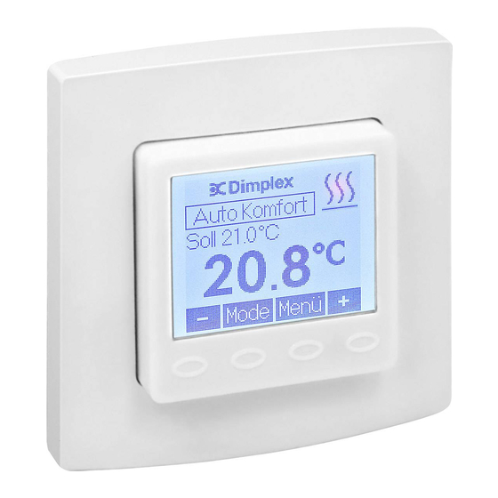
- Page 1 Operating Instructions for Universal Temperature Controller BRTU 101 UN Stand 11.2011...
-
Page 3: Table Of Contents
Table of contents, overview Safety information ..........Application / functional description / emergency operation . -
Page 4: Safety Information
1. Safety information Expert electricians only may open this device in due compliance with the wiring diagram shown in the housing cover / on the housing / represented in the corresponding operating instructions. All expert electricians charged with the execution of such works must comply with the relevant safety regu- lations currently operative and in force. -
Page 5: Application / Functional Description / Emergency Operation
2. Application / functional description / emergency operation The controller described in these instructions is provided for flush installa- tion and has been specially devised for the time-dependent control of the temperatures in individual rooms or of the temperatures produced by elec- tric or warm-water heating systems (systems with normally closed valve actuators). -
Page 6: Operating Instructions
3. Operating instructions The device is equipped with 4 touch keys, all of which have been marked by the symbol . The functions allocated to them may vary in dependence on the operation requirements. The related function is being indicated on the display which exists above the corresponding keys. -
Page 7: Control Operation
4. Control operation Temporary set temperature setting see 4.1 Selection of the operating mode see 4.2 Main menu see 5. Temporary set temperature setting see 4.1... -
Page 8: Temporary Set Temperature Setting
4.1 Temporary set temperature setting Set temperature – 0.5 K Acquisition of the values Return to normal control mode Set temperature + 0.5 K If no key has been activated within a period of approx. 5 seconds, the system returns to normal control mode again. The changed temperature value is being taken over and imported. -
Page 9: Selection Of The Operating Mode
4.2 Selection of the operating mode ▼ ▼ ▼ ▼ Actuating the touch key “Mode” allows to change the operating mode in the order shown below: – Automatic mode (in compliance with the related weekday mode settings) – Comfort mode, permanently –... -
Page 10: Main Menu
5. Main menu ▼ ▼ ▼ ▼ ▼ ▼ ▼ ▼ ▼ ▼ ▼ Submenu Submenu Submenu Submenu Party Holiday Time Date see 5.1 see 5.2 see 5.3 see 5.4 Actuating the key terminates the main menu. - Page 11 5. Main menu ▼ ▼ ▼ ▼ ▼ ▼ ▼ ▼ ▼ ▼ ▼ Submenu Submenu Submenu “weekday Info function “temperature” “settings” programs” see 5.7 see 5.5 see 5.8 see 5.6 Calling of the experts menu see 6.
-
Page 12: Submenu "Party
5.1 Submenu “Party” Party end – 15 minutes Termination of data entry, returning to the main menu Start of the “Party” function Party end + 15 minutes Actuating the touch key starts the party function. Once the pre- adjusted time has been attained, the system switches automatically back to the previous operating mode. -
Page 13: Setting Of The Holiday Data
5.2 Setting of the holiday data and entry of the month in which holidays begin Month in which holidays begin – 1 Termination of the data entry, returning to the main menu Changing over to the day on which holidays begin Month in which holidays begin + 1... - Page 14 5.2 Entry of the day on which holidays begin Day on which holidays begin – 1 Termination of the entry, returning to the main menu Changing over to the month in which holidays end Day on which holidays begin + 1...
- Page 15 5.2 Entry of the day on which holidays end Day on which holidays end – 1 Termination of the entry, returning to the main menu Changing over to the day on which holidays end Day on which holidays end + 1...
- Page 16 5.2 Entry of the day on which holidays end Day on which holidays end – 1 Termination of the entry, returning to the main menu Changing over to the holidays temperature menu Day on which holidays end + 1...
- Page 17 5.2 Entry of the “holiday temperature” Holiday temperature – 0.5 K Termination of entries, returning to the main menu Import of all values, returning to the main menu Holiday temperature + 0.5 K Already existing holiday data can be cancelled by simply changing, via the main menu, over to the holiday submenu.
-
Page 18: Setting Of The Time
5.3 Setting of the time Entry of hours Hour – 1 Termination of entries, returning to the main menu Import of the selected value, changing to the minute entry display Hour + 1... - Page 19 5.3 Entry of minutes Minute – 1 Termination of entries, returning to the main menu Import of the selected value, returning to the main menu Minute + 1 Actuating the key after a change of the minutes, allows to reset the seconds entry to “0”.
-
Page 20: Setting Of The Date
5.4 Setting of the date Entry of the year Year –1 Termination of entries, returning to the main menu Import of the selected value, changing to the month entry display Year + 1... - Page 21 5.4 Entry of the month Month – 1 Termination of entries, returning to the main menu Import of the selected value, changing to the day entry display Month + 1...
- Page 22 5.4 Entry of the day Day – 1 Termination of entries, returning to the main menu Import of the selected value, returning to the main menu Day + 1...
-
Page 23: Setting Of The Set Temperatures
5.5 Setting of the set temperatures Entry of the comfort temperature Comfort temperature – 0.5 K Termination of entries, returning to the main menu Import of the selected value, changing to the ECO temperature entry display Comfort temperature + 0.5 K If using the device as floor temperature controller, the desired floor tem- perature can be set using this menu. - Page 24 5.5 Entry of the ECO temperature ECO temperature – 0.5 K Termination of entries, returning to the main menu Import of the selected value, returning to the main menu ECO temperature + 0.5 K The maximum adjustable ECO temperature value corresponds to the comfort temperature value –...
-
Page 25: Entry Of The Weekday Programs
5.6 Entry of the weekday programs Selection of the weekday Weekday backward Termination of entries, returning to the main menu Changing to the display for the entry of comfort and ECO times Weekday onward... - Page 26 5.6 Selection of the comfort or ECO times Position – 15 minutes Termination of entries. If no changes have been made, the system returns to the display for the selection of the weekday. Otherwise, it changes over to the entry confirmation display. Shifting between comfort or ECO time period Position + 15 minutes...
- Page 27 5.6 Confirmation of entries Termination of entries, returning to the weekday selection display Storing of the entries Change to the menu enabling the copying of entries with respect to other weekdays...
- Page 28 5.6 Import of the entries made with regard to other weekdays Selection backward No import of entries, returning to the weekday selection display Import of entries with respect to the selected weekday(s). Selection forward...
-
Page 29: Information
5.7 Information Returning to the main menu... -
Page 30: Settings
5.8 Settings Selection downward Termination of entries, returning to the main menu Activation or deactivation of the selected function Selection upward... - Page 31 5.8 Settings The following functions are available: 1.Keylock The keylock is activated 2 minutes after actuating any of the touch keys. The key icon appears on the display to indicate this locked state. The touch keys can be reactivated by actuating and holding any of the keys depressed for 10 seconds.
- Page 32 valve and pump protection function is rendered active only if no heating operations were executed within the last week. Unnecessary heating during the heating season is thus avoided, thereby leaving the control system unaf- fected. 4. Self-learning function The self-learning function serves for the autonomous attaining of the comfort temperature at a preset time.
-
Page 33: Experts Menu
6. Experts menu Depressing the right touch key and keeping it depressed for 10 seconds after accessing the “settings” submenu (see page 11) from the main menu, enables to call the experts menu. Caution! This menu enables to make control settings that may only be perfor- med by a qualified heating specialist or an expert electrician. - Page 34 The maximum temperature measured by the floor temperature can be defined within a range from 15 to 42°C. Damages to the floor in consequence of exces- sive temperatures can thus be prevented (factory setting 42°C). 5. Entry of the connected load (entry possible only when using the device as room temperature controller with floor temperature controller function or as floor temperature controller) In order to allow to compensate the self heating of the HTRRUu, the power con-...
-
Page 35: Mounting / Connection
7. Mounting / connection The device equipped with the 50 x 50 mm housing cover can be integrated into almost all currently available flush switch installation frame systems when using DIN 49075 compliant intermediate frames. The device equip- ped with the 55 x 55 mm housing is, likewise, suited for use with different frame systems. -
Page 36: Wiring Diagram And Dimensioned Drawing
8. Wiring diagram and dimensioned drawing Load: max. 2.3kW Ext. sensor... -
Page 37: Important Notice
Important Notice! The single wires of both the power supply cable and the sensor line need to protected against shifting by securing them with one cable tie each as shown here below. In so doing, care is to be taken to ensure that the distance between cable tie and power supply- or sensor line terminal respectively, is always kept as short as possible (max. -
Page 38: Technical Data
9.Technical data Operating voltage: 230 V~, 50 Hz Sensor: NTC – internal; NTC – externally connectable type Switching contact: relay (make contact) Switching capacity: 10(2)A / 230 V~ Setting range: 5 … 30°C (control of room temperatures); 10 … 42°C (control of floor temperature) Switching difference: <1K emperature decrease:... -
Page 39: Accessories
10. Accessories HF-8/4-K2 – External floor temperature sensor, incl. 4 m long cable HF-8/6-K2 – External floor temperature sensor, incl. 6 m long cable THF – Sleeve to ensure the sensor is protected when installing it into the floor screed 11. - Page 40 Glen Dimplex Deutschland GmbH Am Goldenen Feld 18 D-95326 Kulmbach Note on Disposal! Email: 09221709589@dimplex.de Do not dispose of the unit Phone: +49 (0)9221 709-564 with general household waste. The device must be taken to a Fax: +49 (0)9221 709-589 local waste disposal.