Table of Contents
Advertisement
Advertisement
Table of Contents

Related Manuals for LanParty X48


Summary of Contents for LanParty X48
- Page 1 System Board User’s Manual...
- Page 2 Copyright This publication contains information that is protected by copyright. No part of it may be reproduced in any form or by any means or used to make any transformation/adaptation without the prior writ- ten permission from the copyright holders. This publication is provided for informational purposes only.
-
Page 3: Fcc And Doc Statement On Class B
FCC and DOC Statement on Class B This equipment has been tested and found to comply with the limits for a Class B digital device, pursuant to Part 15 of the FCC rules. These limits are designed to provide reasonable protection against harmful interference when the equipment is operated in a residential installation. -
Page 4: Table Of Contents
Table of Contents Warranty....................Static Electricity Precaution..............Safety Measures..................About the Package................Before Using the System Board............Chapter 1 - Introduction..............Specifications........................... Features.............................. Chapter 2 - Hardware Installation............ System Board Layout ......................System Memory.......................... CPU............................... Flame-Freezer Heat Sink....................Jumper Settings..........................Rear Panel I/O Ports...................... -
Page 5: Warranty
Warranty 1. Warranty does not cover damages or failures that arised from misuse of the product, inability to use the product, unauthorized replacement or alteration of components and product specifica- tions. 2. The warranty is void if the product has been subjected to physi- cal abuse, improper installation, modification, accidents or unau- thorized repair of the product. -
Page 6: Static Electricity Precaution
Introduction Static Electricity Precautions It is quite easy to inadvertently damage your PC, system board, components or devices even before installing them in your system unit. Static electrical discharge can damage computer components without causing any signs of physical damage. You must take extra care in handling them to ensure against electrostatic build-up. -
Page 7: About The Package
Introduction About the Package The system board package contains the following items. If any of these items are missing or damaged, please contact your dealer or sales representative for assistance. One system board One Bernstein audio module with cable One Flame-Freezer heat sink kit One IDE round cable One floppy round cable Four Serial ATA data cables... -
Page 8: Chapter 1 - Introduction
• Supports Enhanced Intel SpeedStep Technology (EIST) • Supports Intel Hyper-Threading Technology • Supports 1600/1333/1066/800MHz FSB Chipset • Intel chipset ® - Northbridge: Intel X48 Express chipset ® Intel Fast Memory Access technology ® - Southbridge: Intel ICH9R ® System Memory •... - Page 9 Introduction Storage • Intel ICH9R chip - Intel Matrix Storage technology - Supports up to 6 SATA devices - SATA speed up to 3Gb/s - RAID 0, RAID 1, RAID 0+1 and RAID 5 • JMicron JMB363 PCI Express to SATA and PATA host controller - Supports up to 2 UltraDMA 100Mbps IDE devices - Supports 2 SATA devices - SATA speed up to 3Gb/s...
-
Page 10: Features
Introduction Features The data transfer rate of the high performance DDR2 technology delivers bandwidth of 12.8 Gb/s and beyond. That is twice the speed of the conventional DDR with- out increasing its power consumption. DDR2 SDRAM modules work at 1.8V supply compared to 2.6V memory voltage for DDR modules. - Page 11 Introduction S/PDIF is a standard audio file transfer format that transfers digital audio signals to a device without having to be converted first to an analog format. This prevents the quality of the audio signal from degrading whenever it is converted to analog. S/PDIF is usually found oyn digital audio equipment such as a DAT machine or audio processing device.
- Page 12 Introduction IEEE 1394 is fully compliant with the 1394 OHCI (Open Host Controller Interface) 1.1 specification. It supports up to 63 devices that can run simultaneously on a system. 1394 is a fast external bus standard that supports data transfer rates of up to 400Mbps. In addition to its high speed, it also supports isochronous data transfer which is ideal for video de- vices that need to transfer high levels of data in real-time.
- Page 13 Introduction CPU Overheat Protection has the capability of moni- Overheat toring the CPU’s temperature during system boot up. Protection Once the CPU’s temperature exceeded the tempera- ture limit pre-defined by the CPU, the system will automatically shut- down. This preventive measure has been added to protect the CPU from damage and insure a safe computing environment.
- Page 14 Introduction This function allows you to use the PS/2 Wake-On-PS/2 keyboard or PS/2 mouse to power-on the system. Important: The 5VSB power source of your power supply must support ≥ 720mA. This function allows you to use a USB Wake-On-USB keyboard or USB mouse to wake up a system from the S3 (STR - Suspend To RAM) state.
- Page 15 Introduction Important: The 5VSB power source of your power supply must support ≥ 1A. When power returns after an AC power fail- Power failure ure, you may choose to either power-on the recovery system manually or let the system power-on automatically.
-
Page 16: Chapter 2 - Hardware Installation
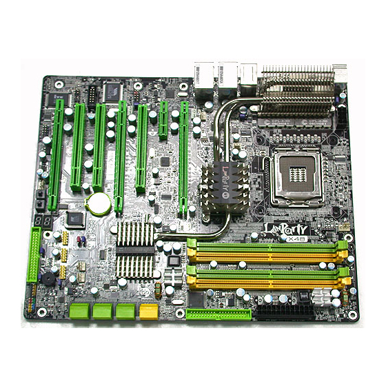
Hardware Installation Chapter 2 - Hardware Installation System Board Layout PS/2 power select (JP7) DIMM 2 DIMM 4 Mouse DIMM 1 DIMM 3 12V power C217 power 1394-0 USB 11 USB 10 USB 6-11 power DRAM select (JP5) Power NB fan LAN 1 Intel USB 9... -
Page 17: System Memory
Hardware Installation Warning: Electrostatic discharge (ESD) can damage your system board, proces- sor, disk drives, add-in boards, and other components. Perform the upgrade instruction procedures described at an ESD workstation only. If such a station is not available, you can provide some ESD protec- tion by wearing an antistatic wrist strap and attaching it to a metal part of the system chassis. -
Page 18: Hardware Installation
Hardware Installation The system board supports the following memory interface. Single Channel (SC) Data will be accessed in chunks of 64 bits (8B) from the memory channels. Virtual Single Channel (VSC) If both channels are populated with different memory configurations, the MCH defaults to Virtual Single Channel. - Page 19 Hardware Installation The table below lists the various optimal operating modes that should be configured for the memory channel operation. Config DIMM 1 DIMM 2 DIMM 3 DIMM 4 No memory Single channel A Single channel A Single channel A Single channel B Single channel B Single channel B...
- Page 20 Hardware Installation DIMM 1 DIMM 2 DIMM 3 DIMM 4 Config P(*)(2,4) P(*)(2,4) Dynamic Mode Addressing P(*)(1,3) P(*)(1,3) Dynamic Mode Addressing P(*)(1,3) P(*)(2,4) P(*)(1,3) P(*)(2,4) Dynamic Mode Addressing P(*)(2,4) P(*)(2,4) Dynamic Mode Addressing P(*)(1,3) P(*)(1,3) Dynamic Mode Addressing P(*)(1,3) P(*)(2,4) P(*)(1,3) P(*)(2,4) Dynamic Mode Addressing...
-
Page 21: Installing The Memory Module
Hardware Installation Installing the Memory Module Note: The system board used in the following illustrations may not resemble the actual board. These illustrations are for reference only. 1. Make sure the PC and all other peripheral devices connected to it has been powered down. 2. - Page 22 Hardware Installation 6. Grasping the module by its edges, position the module above the socket with the “notch” in the module aligned with the “key” on the socket. The keying mechanism ensures the module can be plugged into the socket in only one way. 7.
-
Page 23: Cpu
Hardware Installation Overview The system board is equipped with a surface mount LGA 775 socket. This socket is exclusively designed for installing a LGA 775 packaged Intel CPU. Important: 1. Before you proceed, make sure (1) the LGA775 socket 1. Before you proceed, make sure (1) the LGA775 socket 1. - Page 24 Hardware Installation Cover 4. The CPU socket comes with a cover that is attached with a remov- able protective cap. The Protective cap cap is used to protect the CPU socket against dust and harmful parti- Lever cles. Remove the protec- tive cap only when you are about to install the CPU.
- Page 25 Hardware Installation 8. Position the CPU above the socket. The gold mark on the CPU must align with pin 1 of the CPU socket. Important: Handle the CPU by its edges and avoid touch- ing the pins. Pin 1 of the socket Gold mark 9.
- Page 26 Hardware Installation 10. Once the CPU is in Cover place, move the cover down. 11. Push the lever down to lock the socket. The lever should hook onto the side tab to indicate that the CPU is com- pletely secured in the Lever socket.
- Page 27 Hardware Installation 2. Place the heat sink on Mounting hole top of the CPU. The 4 studs around the heat Mounting hole sink which are used to secure the heat sink onto the system board must match the 4 mounting holes around the socket.
-
Page 28: Flame-Freezer Heat Sink
Hardware Installation Flame-Freezer Heat Sink The heat dissipating effect of a heat sink mounted directly at the place where the heat is produced, such as that of a northbridge, is usually lim- ited. To overcome this problem, the system board uses the heat pipe technology which is an extremely high thermal conductor that can dissipate heat effectively. - Page 29 Hardware Installation 2. Before you proceed, make sure you have already installed the provided I/O shield and system board into the chassis. I/O shield Internal view of the chassis (rear I/O area)
- Page 30 Hardware Installation 3. Remove the screws that hold the metal-plate-covering of the I/O shield. Metal-plate-covering of the I/O shield 4. The base of the heat sink which is used to stabilize the Flame- Freezer heat sink is now accessible. Heat sink base Enlarged view of the heat sink base...
- Page 31 Hardware Installation 5. With the raised bump of the Mounting screws mounting clip facing upward, position the mounting clip on the heat sink as shown on the right. Mounting clip Heat sink Mounting clip 6. With the mounting clip still in place (as shown above), inser t the heat sink from a 45 angle.
- Page 32 Hardware Installation 7. With the clip already in place, secure the heat sink by mounting the 2 provided screws. Internal view of the chassis (rear I/O area) Mounting holes...
- Page 33 Hardware Installation 8. The photos on the right show the properly installed heat sink. Rear view Internal view 9. Replace metal plate previously removed in step 3. Note: The heat sink on the Northbridge is removable allowing you to install a heat sink of your choice.
-
Page 34: Jumper Settings
Hardware Installation Jumper Settings Clear CMOS Data Clearing CMOS Data using JP2 1-2 On: Normal 2-3 On: (default) Clear CMOS Data If you encounter the following, a) CMOS data becomes corrupted. b) You forgot the supervisor or user password. c) The overclocked settings in the BIOS resulted to the system’s in- stability or caused system boot up problems. - Page 35 Hardware Installation ® Clearing CMOS Data using the EZ Clear Function ® EZ Clear bypasses the manual process of using a jumper to clear the CMOS by simply using the reset and power buttons. Important: ® EZ Clear is supported only if standby power is present in the system.
-
Page 36: Usb Power Select
Hardware Installation PS/2 Power Select 1-2 On: 5V 2-3 On: (default) 5VSB Important: The 5VSB power source of your power supply must suppor t ≥720mA. Selecting 5VSB will allow you to use the PS/2 keyboard or PS/2 mouse to wake up the system. USB Power Select USB 6-11 (JP5) - Page 37 Hardware Installation Speaker On/Off Select 1-2 On: 2-3 On: Buzzer Speaker Off Speaker On (default) The system board is equipped with a buzzer which serves as the PC’s speaker. By default the buzzer is “on” allowing you to hear the system’s beep messages and warnings.
- Page 38 Hardware Installation Safe Boot 1-2 On: 2-3 On: Default Safe boot This jumper is used to safely reboot the system whenever the sys- tem hangs and you are unable to restart the system. 1. Power-off the system then unplug the power cord. 2.
-
Page 39: Secondary Rtc Reset
Hardware Installation Secondary RTC Reset JP12 1-2 On: Normal 2-3 On: (default) RTC reset When the RTC batter y is removed, this jumper resets the manageability register bits in the RTC. Note: 1. The SRTCRST# input must always be high when all other RTC power planes are on. - Page 40 Hardware Installation CPU FSB Select JP14 JP15 JP13 By default, JP13 to JP15 are set to pins 1 and 2 On. This setting will allow the system to automatically run according to the CPU’s FSB. If you want to change the setting, please refer to the table below. By CPU FSB 1333 FSB 800...
-
Page 41: Rear Panel I/O Ports
Hardware Installation Rear Panel I/O Ports PS/2 LAN 1 LAN 2 Mouse 1394-0 PS/2 USB 10-11 USB 6-7 USB 8-9 PS/2 Ports and IEEE 1394 Ports PS/2 Mouse PS/2 KB 1394-0 1394-1 PS/2 Mouse and PS/2 Keyboard Ports These ports are used to connect a PS/2 mouse and a PS/2 key- board. - Page 42 Hardware Installation USB Ports and LAN Ports USB 11 USB 10 LAN 1 USB 9 USB 8 LAN 2 USB 7 USB 6 USB 4-5 USB 0-1 USB 2-3 USB Ports The USB ports are used to connect USB 2.0/1.1 devices. The 10-pin connectors allow you to connect 6 additional USB 2.0/1.1 ports.
-
Page 43: Bernstein Audio Module
Hardware Installation Bernstein Audio Module Left audio channel Line-in Ground Ground Line-out Right audio channel Mic-in Center/ CD-in Subwoofer Rear R/L Side R/L 1 0 9 Line out Jet Detect Line out_Left S/PDIF-out Sense N. C. Line out_Right Mic Jet Detect S/PDIF-in Mic_Right Mic_Left... - Page 44 Hardware Installation Coaxial RCA S/PDIF-in and SPDIF-out Jacks These jacks are used to connect external audio output devices using coaxial S/PDIF cables. CD-in Connector The CD-in connector is used to receive audio from a CD-ROM drive, TV tuner or MPEG card. Front Audio Connector The front audio connector is used to connect to the line-out and mic-in jacks that are at the front panel of your system.
-
Page 45: Internal I/O Connectors
Hardware Installation 3. The length of the audio cable provides the option and flexibil- ity of installing the module on any available expansion bracket slot at the rear of the system chassis. Remove the screw of the bracket where you want the audio module installed then re- move the bracket. - Page 46 Hardware Installation Floppy Disk Drive Connector and IDE Connector Floppy Disk Drive Connector The floppy disk drive connector is used to connect a floppy drive. Insert one end of the floppy cable into this connector and the other end-most connector to the floppy drive. The colored edge of the cable should align with pin 1 of this connector.
- Page 47 Hardware Installation IrDA, CIR and Serial (COM) Connectors IRRX Ground N. C. IRTX IrDA CIRTX 5VSB Ground N. C. CIRRX IrDA and CIR Connectors These connectors are used to connect an IrDA module and/or CIR module. Note: The sequence of the pin functions on some IrDA/CIR cable may be reversed from the pin function defined on the system board.
-
Page 48: Cooling Fan Connectors
Hardware Installation Cooling Fan Connectors N. C. Ground Power Power Ground Sense Speed NB fan Control CPU fan Power Power Ground N. C. Ground N. C. 3rd fan 1st fan Power Power Ground N. C. Ground N. C. System fan 2nd fan These fan connectors are used to connect cooling fans. - Page 49 Hardware Installation LEDs DRAM Power LED Standby Diagnostic Power LED DRAM Power LED This LED will light when the system’s power is on. Standby Power LED This LED will light when the system is in the standby mode. Diagnostic LED The Diagnostic LED displays POST codes.
-
Page 50: Power Connectors
Hardware Installation Power Connectors Use a power supply that complies with the ATX12V Power Supply Design Guide Version 1.1. An ATX12V power supply unit has a standard 24-pin ATX main power connector that must be inserted into this connector. 1 2 2 4 +3.3VDC +12VDC +5VDC... - Page 51 Hardware Installation The power connectors from the power supply unit are designed to fit the 24-pin and 8-pin connectors in only one orientation. Make sure to find the proper orientation before plugging the connectors. The FDD-type power connectors are additional power connector.s If you are using more than one graphics cards, we recommend that you plug power cables from your power supply unit to the 5V/12V power connectors.
- Page 52 Hardware Installation Restarting the PC Normally, you can power-off the PC by: 1. Pressing the power button at the front panel of the chassis. 2. Pressing the power switch that is on the system board (note: not all system boards come with this switch). If for some reasons you need to totally cut off the power supplied to the PC, switch off the power supply or unplug the power cord.
-
Page 53: Front Panel Connectors
Hardware Installation Front Panel Connectors RESET SPEAKER HD-LED PWR-LED ATX-SW HD-LED: Primary/Secondary IDE LED This LED will light when the hard drive is being accessed. RESET: Reset Switch This switch allows you to reboot without having to power off the system thus prolonging the life of the power supply or system. - Page 54 Hardware Installation PWR-LED: Power/Standby LED When the system’s power is on, this LED will light. When the system is in the S1 (POS - Power On Suspend) or S3 (STR - Suspend To RAM) state, it will blink every second. Note: If a system did not boot-up and the Power/Standby LED did not light after it was powered-on, it may indicate that the CPU...
-
Page 55: Pci Express Slots
Hardware Installation PCI Express Slots PCI Express x16 (PCIE 1) PCI Express x1 PCI Express x16 (PCIE 3) PCI Express x16 (PCIE 4) PCI Express x16 Install PCI Express x16 graphics card, that comply to the PCI Ex- press specifications, into the PCI Express x16 slot. To install a graph- ics card into the x16 slot, align the graphics card above the slot then press it down firmly until it is completely seated in the slot. -
Page 56: Chapter 3 - Bios Setup
BIOS Setup Chapter 3 - BIOS Setup Award BIOS Setup Utility The Basic Input/Output System (BIOS) is a program that takes care of the basic level of communication between the processor and pe- ripherals. In addition, the BIOS also contains codes for various ad- vanced features found in this system board. -
Page 57: Standard Cmos Features
BIOS Setup Standard CMOS Features Use the arrow keys to highlight “Standard CMOS Features” then press <Enter>. A screen similar to the one below will appear. Phoenix - AwardBIOS CMOS Setup Utility Standard CMOS Features Date <mm:dd:yy> Tue, Oct 30 2007 Item Help Time <hh:mm:ss>... -
Page 58: Bios Setup
BIOS Setup IDE Channel 0 Master to IDE Channel 5 Slave To configure the IDE drives, move the cursor to a field then press <Enter>. The following screen will appear. Phoenix - AwardBIOS CMOS Setup Utility IDE Channel 0 Master Press Enter IDE HDD Auto-Detection Item Help... - Page 59 BIOS Setup Capacity Displays the approximate capacity of the disk drive. Usually the size is slightly greater than the size of a formatted disk given by a disk checking program. Cylinder This field displays the number of cylinders. Head This field displays the number of read/write heads. Precomp This field displays the number of cylinders at which to change the write timing.
- Page 60 BIOS Setup Halt On This field determines whether the system will stop if an error is detected during power up. The default setting is All Errors. No Errors The system boot will not stop for any errors detected. All Errors The system boot will stop whenever the BIOS detects a non-fatal error.
-
Page 61: Advanced Bios Features
BIOS Setup Advanced BIOS Features The Advanced BIOS Features allows you to configure your system for basic operation. Some entries are defaults required by the system board, while others, if enabled, will improve the performance of your system or let you set some features according to your preference. Phoenix - AwardBIOS CMOS Setup Utility Advanced BIOS Features Press Enter... -
Page 62: Hard Disk Boot Priority
BIOS Setup Hard Disk Boot Priority This field is used to select the boot sequence of the hard drives. Move the cursor to this field then press <Enter>. Use the Up or Down arrow keys to select a device then press <+> to move it up or <->... - Page 63 BIOS Setup Boot Up Floppy Seek When enabled, the BIOS will check whether the floppy disk drive installed is 40 or 80 tracks. Note that the BIOS cannot distinguish between 720K, 1.2M, 1.44M and 2.88M drive types as they are all 80 tracks.
- Page 64 BIOS Setup Full Screen Logo Show This field is applicable only if you want a particular logo to appear during system boot-up. Enabled The logo will appear in full screen during system boot- Disabled The logo will not appear during system boot-up.
-
Page 65: Advanced Chipset Features
BIOS Setup Advanced Chipset Features Phoenix - AwardBIOS CMOS Setup Utility Advanced Chipset Features PCI-E Compliancy Mode v1.0a Item Help PEG Force X1 Disabled Menu Level PCI Slot Init Display First ↑↓→← : Move Enter: Select +/-/PU/PD: Value F10: Save ESC: Exit F1: General Help F5: Previous Values... -
Page 66: Integrated Peripherals
BIOS Setup Integrated Peripherals Phoenix - AwardBIOS CMOS Setup Utility Integrated Peripherals Item Help OnChip IDE Device Press Enter Onboard PCI Device Press Enter Menu Level Super IO Device Press Enter USB Device Setting Press Enter ↑↓→← : Move Enter: Select +/-/PU/PD: Value F10: Save ESC: Exit... - Page 67 BIOS Setup SATA Mode This field is used to configure the SATA devices supported by the Intel ICH9R. This option configures the Serial ATA drives as Parallel ATA storage devices. RAID This option allows you to create RAID or Intel Matrix Storage configuration on Serial ATA devices.
- Page 68 BIOS Setup Onboard PCI Device Phoenix - AwardBIOS CMOS Setup Utility Onboard PCI Device Item Help Onboard Lan1 Controller Enabled Onboard Lan2 Controller Enabled Menu Level IEEE 1394 Controller Enabled Onboard HD Audio Enabled ↑↓→← : Move Enter: Select +/-/PU/PD: Value F10: Save ESC: Exit F1: General Help...
-
Page 69: Super Io Device
BIOS Setup Super IO Device Phoenix - AwardBIOS CMOS Setup Utility Super IO Device Power On By Mouse Disabled Item Help Power On By Keyboard Button Only Menu Level Enabled x Power On By Button Enter x KB Power On Password x Hot Key Power On Ctrl-F1 Onboard FDC Controller... - Page 70 BIOS Setup Power On By Button To use the power button to power on the system, set this field to Enabled. KB Power On Password Move the cursor to this field and press <Enter>. Enter your pass- word. You can enter up to 5 characters. Type in exactly the same password to confirm, then press <Enter>.
- Page 71 BIOS Setup IR Mode Select This field is used to select the type of IrDA standard supported by your IrDA device. For better transmission of data, your IrDA periph- eral device must be within a 30 angle and within a distance of 1 meter.
- Page 72 BIOS Setup USB Device Setting Phoenix - AwardBIOS CMOS Setup Utility USB Device Setting USB 1.0 Controller Enabled Item Help USB 2.0 Controller Enabled Menu Level USB Operation Mode High Speed USB Keyboard Function Enabled [Enable] or [Disable] USB Mouse Function Enabled Universal Host USB Storage Function...
- Page 73 BIOS Setup USB Mouse Function Due to the limited space of the BIOS ROM, the support for legacy USB mouse (in DOS mode) is by default set to Disabled. With more BIOS ROM space available, it will be able to support more advanced features as well as provide compatibility to a wide variety of peripheral devices.
-
Page 74: Power Management Setup
BIOS Setup Power Management Setup The Power Management Setup allows you to configure your system to most effectively save energy. Phoenix - AwardBIOS CMOS Setup Utility Power Management Setup ACPI Suspend Type S3(STR) Item Help USB KB WakeUp From S3(S4) Disabled Menu Level Instant-Off... - Page 75 BIOS Setup Soft-Off by PWR-BTTN This field allows you to select the method of powering off your system. Delay 4 Sec. Regardless of whether the Power Management func- tion is enabled or disabled, if the power button is pushed and released in less than 4 sec, the system enters the Suspend mode.
- Page 76 BIOS Setup Resume By Alarm Enabled When Enabled, you can set the time you would like the Soft Power Down (Soft-Off) PC to power-on in the “Time (dd:hh:mm) of Alarm” field. However, if the system is being accessed by incoming calls or the network prior to the time set in the field, the system will give priority to the incoming calls or network.
-
Page 77: Resources Controlled By
BIOS Setup PnP/PCI Configurations This section describes configuring the PCI bus system. It covers some very technical items and it is strongly recommended that only experienced users should make any changes to the default settings. Phoenix - AwardBIOS CMOS Setup Utility PnP/PCI Configurations Resources Controlled By Auto(ESCD) -
Page 78: Irq Resources
BIOS Setup IRQ Resources Move the cursor to this field and press <Enter>. This field is used to set each system interrupt to either Reserved or PCI Device. Phoenix - AwardBIOS CMOS Setup Utility IRQ Resources PCI Device IRQ-3 assigned to Item Help PCI Device IRQ-4 assigned to... -
Page 79: Pc Health Status
BIOS Setup PC Health Status Phoenix - AwardBIOS CMOS Setup Utility PC Health Status Shutdown Temperature C/185 Item Help >50 CPUFan Fully On If CPUTemp Menu Level <25 CPUFan Turn OFF if CPUTemp CHSFan Fully On If CHSTemp >35 CHSFan Turn OFF if CHSTemp <25 >55 NB Fan Fully On If NB Temp... - Page 80 BIOS Setup 2. If you want to reduce the CPU fan’s noise or prevent CPU overheat, select a lower temperature in the “CPUFan Fully On If CPUTemp” field to allow the CPU fan to rotate full speed at the selected lower temperature. CHSFan Fully On If CHSTemp This field is used to select the system’s temperature at which the chassis fan will rotate at full speed.
-
Page 81: Genie Bios Setting
BIOS Setup Genie BIOS Setting Phoenix - AwardBIOS CMOS Setup Utility Genie BIOS Setting Item Help CPU Feature Press Enter DRAM Timing Press Enter Menu Level Exit Setup Shutdown Mode 2 Clock VCO Divider Auto CPU Clock Ratio Target CPU Clock 1862 MHz CPU Clock 266 MHz... - Page 82 BIOS Setup Important: Selecting an external bus clock other than the default setting may result to the processor’s or system’s instability and are not guaranteed to provide better system performance. Boot Up Clock This field is used to select the boot up clock. DRAM Speed This field is used to select the clock speed of the DIMM.
- Page 83 BIOS Setup CPU Feature Move the cursor to this field and press <Enter>, the following screen will appear: Phoenix - AwardBIOS CMOS Setup Utility CPU Feature Thermal Management Control Enabled Item Help Disabled Limit CPUID MaxVal Menu Level Auto C1E Function Execute Disable Bit Enabled Virtualization Technology...
- Page 84 BIOS Setup Virtualization Technology When this field is set to Enabled, the VMM can utilize the additional hardware capabilities provided by Vanderpool Technology.
-
Page 85: Dram Timing
BIOS Setup DRAM Timing Move the cursor to this field and press <Enter>. The following screen will appear. Phoenix - AwardBIOS CMOS Setup Utility DRAM Timing Item Help Auto CAS Latency Time (tCL) Auto Precharge Delay (tRAS) Menu Level Auto RAS# Precharge (tRP) RAS# to CAS# Delay (tRCD) Auto... - Page 86 BIOS Setup Write to PRE Delay (tWR) The options are Auto, and 6 to 18. REF to ACT Delay (tRFC) The options are Auto, and 16 to 33. Rank Write to Read (tWTR) The options are Auto, and 6 to 18. ACT to ACT Delay (tRRD) The options are Auto, and 1 to 15.
- Page 87 BIOS Setup Voltage Setting Move the cursor to this field and press <Enter>. The following screen will appear. Phoenix - AwardBIOS CMOS Setup Utility Voltage Setting Item Help Auto CPU VID Control Auto CPU VID Special Add Menu Level 1.972V DRAM Voltage Control 1.070V SB 1.05V Voltage...
- Page 88 BIOS Setup SB 1.05V Voltage The options are 1.05V, 1.133V, 1.217V and 1.3V. SB Core/CPU PLL Voltage The options are 1.5V, 1.6V, 1.7V and 1.8V. NB Core Voltage The options are 1.25V to 1.55V. CPU VTT Voltage This field is used to select the CPU’s voltage. Vcore Droop Control This field is used to enable or disable the Vcore Droop control.
- Page 89 BIOS Setup CPU Core Voltage This field will show the CPU’s current voltage. DRAM Voltage This field will show the DRAM’s current voltage. NB Core Voltage This field will show the NB’s current core voltage. CPU VTT Voltage This field will show the HT Link’s current voltage.
-
Page 90: Cmos Reloaded
BIOS Setup CMOS Reloaded The CMOS Reloaded submenu allows you to save different configu- rations and when needed, allows you to conveniently restore one of these previously saved configurations. Highlight CMOS Reloaded in the main menu then press <Enter>. Phoenix - AwardBIOS CMOS Setup Utility CMOS Reloaded Item Help Auto Save Bootable Setting... - Page 91 BIOS Setup Auto Save Bootable Setting This field is used to automatically save the last bootable setting from CMOS to an area in the SEEPROM referred to as the backup bank. To use this function: 1. Set this field to Enabled. 2.
- Page 92 BIOS Setup Saving, Loading and Naming BIOS Settings For overclockers who require different sets of settings for various system environments or operating systems, CMOS Reloaded allows you to save, load and name up to four sets of BIOS settings - in the “User Defined Setting Bank #1”...
- Page 93 BIOS Setup Load from this Bank To load the setting saved in the bank, move the cursor to “Load from this Bank” then press <Enter>. The setting in this bank will replace the current setting. Make sure to save before you exit the BIOS setup utility by selecting “Y”...
-
Page 94: Load Optimized Defaults
BIOS Setup Load Optimized Defaults The “Load Optimized Defaults” option loads optimized settings from the BIOS ROM. Use the default values as standard values for your system. Highlight this option in the main menu and press <Enter>. Phoenix - AwardBIOS CMOS Setup Utility Standard CMOS Features Genie BIOS Setting Advanced BIOS Features... -
Page 95: Set Supervisor Password
BIOS Setup Set Supervisor Password If you want to protect your system and setup from unauthorized entry, set a supervisor’s password with the “System” option selected in the Advanced BIOS Features. If you want to protect access to setup only, but not your system, set a supervisor’s password with the “Setup”... -
Page 96: Set User Password
BIOS Setup Set User Password If you want another user to have access only to your system but not to setup, set a user’s password with the “System” option se- lected in the Advanced BIOS Features. If you want a user to enter a password when trying to access setup, set a user’s password with the “Setup”... -
Page 97: Save & Exit Setup
BIOS Setup Save & Exit Setup When all the changes have been made, highlight “Save & Exit Setup” and press <Enter>. Phoenix - AwardBIOS CMOS Setup Utility Standard CMOS Features Genie BIOS Setting Advanced BIOS Features CMOS Reloaded Advanced Chipset Features Load Optimized Defaults Integrated Peripherals Set Supervisor Password... -
Page 98: Exit Without Saving
BIOS Setup Exit Without Saving When you do not want to save the changes you have made, high- light “Exit Without Saving” and press <Enter>. Phoenix - AwardBIOS CMOS Setup Utility Standard CMOS Features Genie BIOS Setting Advanced BIOS Features CMOS Reloaded Advanced Chipset Features Load Optimized Defaults... -
Page 99: Raid Bios
BIOS Setup RAID BIOS Intel RAID BIOS The Intel RAID BIOS utility is used to configure and manage RAID on Serial ATA drives connected to SATA 1 to SATA 6. When the system powers-up and all drives have been detected, the Intel RAID BIOS status message screen will appear. -
Page 100: Updating The Bios
BIOS Setup Updating the BIOS To update the BIOS, you will need the new BIOS file and a flash utility, AWDFLASH.EXE. You can download them from DFI’s web site or contact technical support or your sales representative. 1. Save the new BIOS file along with the flash utility AWDFLASH.EXE to a floppy disk. - Page 101 BIOS Setup 6. The following will appear. Do You Want to Save BIOS (Y/N) This question refers to the current existing BIOS in your system. We recommend that you save the current BIOS and its flash utility; just in case you need to reinstall the BIOS. To save the current BIOS, press <Y>...
-
Page 102: Chapter 4 - Supported Software
Supported Software Chapter 4 - Supported Software Drivers, Utilities and Software Applications The CD that came with the system board contains drivers, utilities and software applications required to enhance the performance of the system board. Insert the CD into a CD-ROM drive. The autorun screen will appear. If after inserting the CD, "Autorun"... -
Page 103: Intel Chipset Device Software
Supported Software Intel Chipset Device Software On the left side of the autorun screen, click the “CHIPSET” icon. 1. Click “Intel(R) Chipset Device Software” on the main menu. 2. Setup is now ready to install the utility. Click Next. -
Page 104: Supported Software
Supported Software 3. Read the license agree- ment then click Yes. 4. Go through the readme document for system requirements and instal- lation tips then click Next. 5. Setup is now installing the driver. Click Next to continue. - Page 105 Supported Software 6. Click “Yes, I want to restar t this computer now” then click Finish. Restar ting the system will allow the new software installation to take effect.
- Page 106 Supported Software Microsoft .NET Framework On the left side of the autorun screen, click the “GRAPHICS” icon. 1. Click “Microsoft .NET Framework” on the main menu. 2. Setup is now ready to install the utility. Click Next.
- Page 107 Supported Software 3. Read license agreement then click “I accept the terms of the License Agreement. ” . Click Install. 4. Setup is now installing the driver.
- Page 108 Supported Software 5. Click Finish. Reboot the system for the new software installation to take effect. Graphics Drivers The CD provides both ATI Radeon driver and nVidia GForce 8 series driver. Install the driver according to the graphics card that you are using. For ATI Radeon graphics card, select ATI Radeon Driver.
-
Page 109: Realtek Audio Driver
Supported Software Realtek Audio Driver On the left side of the autorun screen, click the “AUDIO” icon. 1. Click “Realtek Audio Driver” on the main menu. 2. Setup is now ready to install the audio driver. Click Next. 3. Setup currently configuring the new driver’s installation. - Page 110 Supported Software 4. Setup is now processing the settings. 5. Select the desired option then click Next. 6. Click “Yes, I want to restar t my computer now” then click Finish. Restar ting the system will allow the new software installation to take effect.
- Page 111 Supported Software Marvell LAN Driver On the left side of the autorun screen, click the “NETWORK” icon. 1. Click “Mar vell LAN Driver” on the main menu. 2. Setup is now ready to install the driver. Click Next. 3. Read license agreement then click “I accept the terms in the...
- Page 112 Supported Software 4. Click Install to begin the installation. 5. After completing installa- tion, click Finish to exit setup. Reboot your system for software installation to take effect.
- Page 113 Supported Software Marvell Teaming Utility On the left side of the autorun screen, click the “NETWORK” icon. 1. Click “Mar vell Teaming Utility” on the main menu. 2. Setup is now preparing the wizard. 3. Setup is now ready to install the utility.
- Page 114 Supported Software 4. Read license agreement, click “I accept the terms in the license agreement.” then click Next. 5. Go through the readme document for system requirements and installa- tion tips then click Next. 6. Click Install to begin the installation.
- Page 115 Supported Software 7. Click Finish.
-
Page 116: Smart Guardian
Supported Software Smart Guardian The Smart Guardian utility is capable of monitoring the system’s tempera- ture, fan speed, voltage, etc. and allows you to manually set a range (Highest and Lowest Limit) to the items being monitored. If the settings/ values are over or under the set range, a warning message will pop-up. - Page 117 Supported Software 3. Fill in the necessar y information then click Next.. 4. Click Next to install or click Browse to select another folder. 5. Select an option in accordance to the system that you are using then click Next.
- Page 118 Supported Software 6. After completing installa- tion, click Finish to exit setup. Restarting the system will allow the utility to take effect.
-
Page 119: Installation Notes
Supported Software USB 2.0 Drivers ® Windows ® If your Windows XP CD already includes Service Pack 1, the USB 2.0 driver will automatically install when you install the operating system. If the CD does not include Service Pack 1, it is available for download at Microsoft’s Windows Update website. -
Page 120: Chapter 5 - Raid
RAID Chapter 5 - RAID The Intel ICH9R chip alows configuring RAID on Serial ATA drives connected to SATA 1 to SATA 6. It supports RAID 0, RAID 1, RAID 0+1 and RAID 5. The JMicron JMB363 chip allows configuring RAID on another 2 Se- rial ATA drives connected to SATA 7 and SATA 8. - Page 121 RAID Settings To enable the RAID function, the following settings are required. 1. Connect the Serial ATA drives. 2. Configure Serial ATA in the Award BIOS. 3. Configure RAID in the RAID BIOS. 4. Install the RAID driver during OS installation. 5.
- Page 122 RAID Configure RAID in the JMicron RAID BIOS When the system powers-up and all hard disk drives have been detected, the JMicron RAID BIOS status message screen will appear. Press the <Ctrl> and <J> keys simultaneously to enter the utility. The utility allows you to build a RAID system on Serial ATA drives.
- Page 123 RAID Step 5: Install the Intel Matrix Storage Manager The Intel Matrix Storage Manager can be installed from within Windows. It allows RAID volume management (create, delete, migrate) from within the operating system. It will also display useful SATA device and RAID volume information.
- Page 124 RAID 5. Read warning carefully then click Next. 6. Read license agreement then click Yes. 7. Go through the readme document view system requirements and installation information then click Next. 8. Follow the remainder of the steps shown on the screen; clicking “next” each time you finish a step.
- Page 125 RAID Step 6: Install the JMB36X Driver On the left side of the autorun screen, click the “RAID” icon. 1. Click “JMB36X Driver” on the main menu. 2. Setup is now ready to install the driver. Click Next. 3. Click Install to begin the installation.
- Page 126 RAID 4. Setup is now installing the driver. 5. Follow the remainder of the steps listed on the screen; clicking “next” each time you finish a step. 6. Click “Yes, I want to restar t my computer now” then click Finish. Restarting the system will allow the new software installation to take effect.
-
Page 127: Chapter 6 - Ati Crossfire Technology
ATI CrossFire Technology Chapter 6 - ATI CrossFire Technology ATI’s CrossFire technology drives your PC to a new peak of per- formance. By connecting a Radeon CrossFire Edition graphics card and a standard PCI Express graphics card, the power of these multi- ple GPUs (Graphics Processing Units) within the system will acceler- ate your gaming performance and improve image quality. -
Page 128: Ati Crossfire Technology
ATI CrossFire Technology Features Regardless of the type of operating mode used, the completed frames from both GPUs are sent to the Compositing Engine on the CrossFire Edition graphics card, which then sends them on to the display device. • Supertile Mode Supertiling divides your screen image into subsections like “tiles”... - Page 129 ATI CrossFire Technology Graphics Cards Requirements ® ® 1. One Radeon X850 / Radeon X800 CrossFire Edition graphics card. ® ® 2. One standard PCI Express Radeon X850 or Radeon X800 graphics card. ® The Radeon X850 CrossFire Edition card works with any standard PCI Express Radeon X850 graphics card (Radeon X850 PRO, Radeon X850 XT or Radeon X850 XT Platinum Edition) from ATI or any of its partners including cards previously...
- Page 130 ATI CrossFire Technology The PCI Express x16 Slots PCIE 1 PCIE 3 PCIE 4 Configurations • 2-way CrossFire at x16/x16 bandwidth • 2-way CrossFire + Physics at x16/x16/x4 bandwidth...
- Page 131 ATI CrossFire Technology CrossFire Setup Note: The system board used in the following illustrations may not resemble the actual board. These illustrations are for reference only. 1. Power-off the system and monitor then unplug the power cord. 2. Remove the screw of the bracket that is opposite the PCIE 1 slot then remove the bracket.
- Page 132 ATI CrossFire Technology 5. Remove the screw of the bracket that is opposite the PCIE 3 slot then remove the bracket. PCIE 3 6. Align the standard PCI Express graphics card (Slave) above the PCIE 3 slot then press it down firmly until it is completely seated in the slot.
- Page 133 ATI CrossFire Technology 8. The CrossFire Edition graphics card comes with an external cable. Plug one end of the external cable to a connector on the CrossFire Edition graphics card as shown below. CrossFire Edition graphics card 9. Now plug the other end of the external cable to the DVI-I con- nector on the standard PCI Express graphics card.
- Page 134 ATI CrossFire Technology 11. Connect auxiliary power source from the power supply unit to the graphics cards. 12. Install the graphics cards’ drivers then restart the system for the drivers to take effect. 13. When you enter the operating system, you will no- tice the ATI Catalyst Control Center icon added onto your desktop.
- Page 135 ATI CrossFire Technology 16. The screen on the right indicates that CrossFire has been enabled. Make sure to restart the PC for CrossFire to take effect.
-
Page 136: Appendix A - System Error Message
System Error Message Appendix A - System Error Message When the BIOS encounters an error that requires the user to correct something, either a beep code will sound or a message will be displayed in a box in the middle of the screen and the message, PRESS F1 TO CONTINUE, CTRL-ALT-ESC or DEL TO ENTER SETUP, will be shown in the information box at the bottom. - Page 137 System Error Message setting than indicated in Setup. Determine which setting is correct, either turn off the system and change the jumper or enter Setup and change the VIDEO selection. FLOPPY DISK(S) fail (80) Unable to reset floppy subsystem. FLOPPY DISK(S) fail (40) Floppy type mismatch.
-
Page 138: Appendix B - Troubleshooting
Troubleshooting Appendix B - Troubleshooting Troubleshooting Checklist This chapter of the manual is designed to help you with problems that you may encounter with your personal computer. To efficiently troubleshoot your system, treat each problem individually. This is to ensure an accurate diagnosis of the problem in case a problem has multiple causes. -
Page 139: Power Supply
Troubleshooting The picture seems to be constantly moving. 1. The monitor has lost its vertical sync. Adjust the monitor’s vertical sync. 2. Move away any objects, such as another monitor or fan, that may be creating a magnetic field around the display. 3. -
Page 140: Hard Drive
Troubleshooting Hard Drive Hard disk failure. 1. Make sure the correct drive type for the hard disk drive has been entered in the BIOS. 2. If the system is configured with two hard drives, make sure the bootable (first) hard drive is configured as Master and the sec- ond hard drive is configured as Slave. - Page 141 Troubleshooting 3. Verify that the attached serial device works by attaching it to a serial port that is working and configured correctly. If the serial device does not work, either the cable or the serial device has a problem. If the serial device works, the problem may be due to the onboard I/O or the address setting.