Advertisement
HOME THEATER SPEAKER SYSTEM
The NX-210P and NX-C210 loudspeakers are not field serviceable and must be replaced as complete units.
This manual has been provided for the use of authorized YAMAHA Retailers and their service personnel.
It has been assumed that basic service procedures inherent to the industry, and more specifically YAMAHA Products, are already known and understood by the users,
and have therefore not been restated.
WARNING:
Failure to follow appropriate service and safety procedures when servicing this product may result in personal injury, destruction of expensive
components, and failure of the product to perform as specified. For these reasons, we advise all YAMAHA product owners that any service
required should be performed by an authorized YAMAHA Retailer or the appointed service representative.
IMPORTANT:
The presentation or sale of this manual to any individual or firm does not constitute authorization, certification or recognition of any applicable
technical capabilities, or establish a principle-agent relationship of any form.
The data provided is believed to be accurate and applicable to the unit(s) indicated on the cover. The research, engineering, and service departments of YAMAHA are
continually striving to improve YAMAHA products. Modifications are, therefore, inevitable and specifications are subject to change without notice or obligation to
retrofit. Should any discrepancy appear to exist, please contact the distributor's Service Division.
WARNING:
Static discharges can destroy expensive components. Discharge any static electricity your body may have accumulated by grounding yourself to the
ground buss in the unit (heavy gauge black wires connect to this buss).
IMPORTANT:
Turn the unit OFF during disassembly and part replacement. Recheck all work before you apply power to the unit.
CONTENTS
TO SERVICE PERSONNEL . . . . . . . . . . . . . . . . . . . . 1
SW-P201 REAR PANELS . . . . . . . . . . . . . . . . . . . 1-2
SPECIFICATIONS . . . . . . . . . . . . . . . . . . . . . . . . . . . . 3
SW-P201 DISASSEMBLY PROCEDURES . . . . . . . . . 4
1 0 0 7 0 9
NS-P210
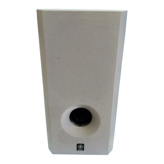
NS-P210 is composed of NX-210P, NX-C210 and SW-P201.
NX-210P x 4
IMPORTANT NOTICE
SERVICE MANUAL
SERVICE MANUAL
NX-C210
SW-P201 BLOCK DIAGRAM . . . . . . . . . . . . . . . . . . . 5
SW-P201 PRINTED CIRCUIT BOARD . . . . . . . . . 6-7
SW-P201 SCHEMATIC DIAGRAM . . . . . . . . . . . . . . . 8
PARTS LIST . . . . . . . . . . . . . . . . . . . . . . . . . . . . . 9-14
NS-P210
SW-P201
Advertisement

Related Manuals for Yamaha NS-P210


Summary of Contents for Yamaha NS-P210
-
Page 1: Table Of Contents
The data provided is believed to be accurate and applicable to the unit(s) indicated on the cover. The research, engineering, and service departments of YAMAHA are continually striving to improve YAMAHA products. Modifications are, therefore, inevitable and specifications are subject to change without notice or obligation to retrofit. -
Page 2: To Service Personnel
NS-P210 TO SERVICE PERSONNEL AC LEAKAGE 1. Critical Components Information. EQUIPMENT WALL TESTER OR Components having special characteristics are marked Z OUTLET UNDER TEST EQUIVALENT and must be replaced with parts having specifications equal to those originally installed. 2. Leakage Current Measurement (For 120V Models Only). - Page 3 NS-P210 SW-P201 A model SW-P201 R model...
-
Page 4: Specifications
Weight ............0.7 kg (1 lbs. 8 oz) Finish ................ Gray color SW-P201 (SUB WOOFER) Type ....Advanced Yamaha Active Servo Technology Output Power ..50 W(100 Hz, 5 ohms at T.H.D. = 10 %) Input Sensitivity INPUT1 (SP) ............1.2 V INPUT2 (PJ) ............ -
Page 5: Sw-P201 Disassembly Procedures
NS-P210 SW-P201 DISASSEMBLY PROCEDURES (Remove parts in the order as numbered.) 1. Removal of Front Grille The front grille is fixed to the cabinet with dowels at 6 locations. * As a screwdriver (for slotted head screw) is used for removal, use special care not to cause damage to the cabinet. -
Page 6: Sw-P201 Block Diagram
NS-P210 SW-P201 BLOCK DIAGRAM... - Page 7 NS-P210 SW-P201 PRINTED CIRCUIT BOARD (Component side) AMP P. C. B. ( A ) FROM : AMP (B) FROM : AMP (C) TO : AMP (B) FROM : AMP (D) TO : SPEAKER AMP P. C. B. ( C )
-
Page 8: Sw-P201 Printed Circuit Board
NS-P210 SW-P201 PRINTED CIRCUIT BOARD (Component side) R only AMP P. C. B. ( B ) VOLTAGE SELECTOR TO : AMP (E) FROM : POWER CORD TO : AMP (A) TO : AMP (A) AMP P. C. B. ( D ) AMP P. -
Page 9: Sw-P201 Schematic Diagram
NS-P210 IC1 : BA4558N SW-P201 SCHEMATIC DIAGRAM Dual OP-Amp – – POWER AMP -14.3 µ IC2, 3, 7, 8 : PC4570HA Dual OP-Amp – – 14.3 –Vm –Vm LIMITER 14.3 IC4 : STK404-050 AF Power Amp -0.1 -0.1 -14.3 11.1 10.4... -
Page 10: Parts List
NS-P210 WARNING PARTS LIST Components having special characteristics are marked Z and must be replaced with parts having specifications equal to those originally installed. Carbon resistors (1/6W or 1/4W) are not included in the ELECTRICAL PARTS ELECTRICAL PARTS List. For the parts No. of the carbon resistors, refer to last page. - Page 11 NS-P210 SW-P201 P.C.B. AMP Schm Schm Ref. PART NO. Description Remarks Ref. PART NO. Description Remarks AAX14790 P.C.B. AMP(UC) 330571 UG412220 C.CE 220pF 50V 065404 AAX14800 P.C.B. AMP(R) 330572 UG412220 C.CE 220pF 50V 065404 AAX14810 P.C.B. AMP(A)BG 330573 FX607210 C.EL...
- Page 12 NS-P210 SW-P201 P.C.B. AMP Schm Schm Ref. PART NO. Description Remarks Ref. PART NO. Description Remarks VS883300 TR 2SB1565 E,F 044140 AAX12590 TR 2SC2240 GR BL 073532 AAX12590 TR 2SC2240 GR BL 073532 AAX09180 FET 2SK304 E 051061 AAX11950 R.CAR.FP 1Ω...
- Page 13 NS-P210 SW-P201 EXPLODED VIEW...
- Page 14 NS-P210 SW-P201 MECHANICAL PARTS Ref. PART NO. Description Remarks Markets AAX13510 ENCLOSURE 058581 AAX12290 FOOT 055357 XY559A00 SPEAKER 16cm JA1678 058529 AAX13590 GRILLE ASS’Y 058579 AAX12930 SEAL 056813 AAX14790 P.C.B. ASSY 330571 (UC) AAX14800 P.C.B. ASSY 330572 AAX14810 P.C.B. ASSY...
- Page 15 NS-P210 Parts List for Carbon Resistors Value 1/4W Type Part No. 1/6W Type Part No. Value 1/4W Type Part No. 1/6W Type Part No. 1.0 Ω 3100 3100 7100 10 kΩ 7100 HJ35 HF85 HF45 HF45 1.8 Ω 3180 7110 11 kΩ...