
Related Manuals for Zoom 5363


Summary of Contents for Zoom 5363
- Page 1 Cable Modem/Router Cable Modem plus Dual-band Wireless-AC Router U S E R M A N U A L ...
- Page 2 Do not place the cable modem in a confined space that may cause overheating. • Do not restrict the flow of air around the cable modem. • Zoom Telephonics assumes no liability for damage caused by any improper use of the cable modem. ...
-
Page 3: Table Of Contents
Changing your Wireless Network Name (SSID) and Pre‐Shared Key ............30 Setting Up Security Using WEP ........................32 Disabling Security ............................33 CHAPTER 5 ONLINE GAMING ............... 34 Gaming .................................34 DMZ Host..............................35 Port Triggers..............................37 CHAPTER 6 ADVANCED SETTINGS.............. 40 Changing Default Settings..........................40 Accessing the Zoom Configuration Manager ....................41 Understanding the Configuration Manager Interface Screens..............42 Configuration Manager Interface Menus .....................43 CHAPTER 7 STATUS PAGE................45 Status................................45 CHAPTER 8 WIRELESS SETTINGS ............... 46 Radio................................46 ... - Page 4 Primary Network ............................49 Guest Network..............................53 Advanced ..............................58 WPS ................................60 Bridging ................................62 Access Control ..............................63 WMM (Wi‐Fi Multimedia) ..........................66 Neighbor APs ..............................68 CHAPTER 9 BASIC MENU OPTIONS............. 70 Basic LAN Settings ............................70 DHCP................................72 WAN Settings..............................73 My Network..............................75 CHAPTER 10 ADVANCED MENU OPTIONS ..........77 MAC Filtering..............................77 IP Filtering ..............................79 Port Filtering..............................81 Port Forwarding ............................83 Port Triggers..............................85 DMZ Host..............................87 DDNS ................................89 RIP Setup ..............................91...
- Page 5 Backup/Restore Settings..........................129 CHAPTER 15 CABLE MODEM MENU OPTIONS ......... 131 Cable Modem Device Information......................131 Connection ..............................133 Restart/Restore Factory/Frequency set ......................135 APPENDIX A: TROUBLESHOOTING TIPS........... 136 APPENDIX B: IF YOU NEED HELP .............. 140 APPENDIX C: COMPLIANCE................ 141 7 ...
-
Page 6: Chapter 1 Getting Started
CM MAC address. You may also be asked for your cable modem's model name and number, which is ZOOM 5363. If you need the modem's serial number, you can find it near the MAC address on the bottom label. - Page 7 • If you haven’t already set up your Cable Modem/Router using the Quick Start, go Chapter 2: Installing the Cable Modem/Router. • If you have already installed your cable modem and want to learn more about how to connect both wired and wireless computers and other devices to your Cable Modem/Router go to: Chapter 3: Connecting Devices to your Cable Modem/Router.
-
Page 8: Chapter 2 Installing The Cable Modem/Router
Zoom cable modem. If there’s an Ethernet cable plugged into the old cable modem, unplug the Ethernet cable from the old cable modem and plug it into any of the Zoom cable modem’s LAN jacks. - Page 9 TV set-top box and another coaxial cable from the other OUT jack to your cable modem. You can see that this approach uses one splitter and 2 additional coaxial cables, each of which has male connectors on each end. Some electronics retailers carry the Zoom 9 ...
- Page 10 They’ll normally ask for the information mentioned above Before installing your cable modem please read this. Some cable companies also let you just open the browser on a computer that’s connected to the Zoom cable modem. A setup page comes up automatically, and you follow the instructions.
- Page 11 Now that your cable modem is connected, do this. When your cable modem first connects to your cable service provider, allow 5 to 30 minutes for the cable modem to connect to the network. The cable modem uses this time to locate and connect to the appropriate channels for communication.
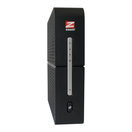
- Page 12 Front Panel LEDs LIGHT COLOR DESCRIPTION ON: Power is supplied to the Cable Modem/Router. Green OFF: Power is not supplied to the Cable Power Modem/Router. Blinking: Scanning for downstream channel Green ON: Synchronized on 1 channel only Green or Blue ON: Synchronized with more than 1 Receive Blue channel (Downstream Bond mode)
- Page 13 Back Panel LAN 1-4 (Gigabit Ethernet 1-4) Four 10/100/1000 auto-sensing Ethernet ports for computers and other devices that have an Ethernet port. RESET Press and hold this recessed button at least 8 seconds in the unlikely event that you want to restore the default factory settings.
-
Page 14: Chapter 3 Connecting Devices To The Cable Modem/Router
Connecting Devices to the Cable Modem/Router This chapter explains how to connect devices (computers, phones, tablets, game stations, etc.) to the Cable Modem/Router. These devices can be connected either wirelessly or to one of the Ethernet ports on your Cable Modem/Router. If you are connecting a computer or other device to an Ethernet LAN port of the Cable Modem/Router, please go to Connecting Additional Computers and/or Other Devices to... -
Page 15: Establishing Your Wireless Network
To select Model 5363’s 5 GHz network for a client device, pick the network ending in 5G. You may want to try both SSIDs to see which one gives you better speed and range. - Page 16 (page 21) computers with built-in wireless capabilities. If you are using a Macintosh computer see the instructions on page 22 for Connecting a Macintosh OS X Computer with Built-in Wireless Capabilities. Some older Windows computers may have built-in wireless networking capabilities, but not use the Windows 8, 7, Vista, or XP utility to configure wireless networking.
-
Page 17: Connecting A Wireless-Enabled Device (Including The Iphone Or Other Cellular Phones, Ipad Or Other Tablets, The Ipod Touch, Etc.) To The Cable Modem/Router
Connecting a Wireless-enabled Device (including the iPhone or other cellular phones, iPad or other tablets, the iPod Touch, etc.) to the Cable Modem/Router 1 Select the wireless-enabled computer or device that you want to add to the network. The device should have software that will let it perform a site search to scan for available wireless networks in your area. -
Page 18: Connecting A Windows 8.1 Or Windows 8 Computer With Built-In Wireless Capabilities
Connecting a Windows 8.1 or Windows 8 Computer with Built-in Wireless Capabilities 1 On the desktop, click the Wireless Network Icon in your computer’s notification area. 2 If available, click on Zoomxxxx_5G to connect to your Cable Modem/Router’s 5 GHz network. -
Page 19: Connecting A Windows 7 Computer With Built-In Wireless Capabilities
Connecting a Windows 7 Computer with Built-in Wireless Capabilities 1 Click the Wireless Network Configuration utility icon in your computer’s system tray. 2 If available, click on Zoomxxxx_5G to connect to your Cable Modem/Router’s 5 GHz network. If you do not see Zoomxxxx_5G than most likely your wireless adapter does not support the 5 GHz network, so go ahead and click on Zoomxxxx. -
Page 20: Connecting A Windows Vista Computer With Built-In Wireless Capabilities
Connecting a Windows Vista Computer with Built-in Wireless Capabilities 1 From the Start menu select Connect to 2 If available, click on Zoomxxxx_5G to connect to your Cable Modem/Router’s 5 GHz network. If you do not see Zoomxxxx_5G than most likely your wireless adapter does not support the 5 GHz network, so go ahead and click on Zoomxxxx. -
Page 21: Connecting A Windows Xp Computer With Built-In Wireless Capabilities
To disconnect from the current network: 1 From the Windows Start menu, select Connect to. 2 In the Disconnect or Connect to another network dialog box, select the current network and click Disconnect. 3 In the Are You Sure? message box, click Disconnect again. 4 In the next dialog box, you can connect to another network or click Close to complete the disconnect procedure. -
Page 22: Connecting A Macintosh Os X Computer With Built-In Wireless Capabilities
Connecting a Macintosh OS X Computer with Built-in Wireless Capabilities 1 Click the Wi-Fi icon in the menu bar. If the Wi-Fi icon does not appear on your menu bar, please refer to your built-in Macintosh documentation for how to enable wireless. Note: On versions prior to OS 10.7 the Wi-Fi icon is called AirPort. -
Page 23: Connecting A Computer With A Wireless Adapter To The Cable Modem/Router
Connecting a Computer with a Wireless adapter to the Cable Modem/Router 1 Go to the computer that is set up with a wireless adapter that you want to add to the network. For many wireless adapters, you will use their configuration manager software and click a Scan button or select a Site Scan, Scan Networks, or other similarly named tab to do a site search. -
Page 24: Using Wps As An Alternative Way To Set Up Your Wireless Network
3 Select or click on Disconnect or similarly-named button. Using WPS as an alternative way to set up your Wireless Network If all the Wi-Fi compatible wireless devices on your network support WPS, you can choose to quickly setup your wireless network by pushing the WPS button on your cable modem/router and on each wireless device connecting to your cable modem/router. - Page 25 Windows 7 Windows 8.1 or Windows 8 5 Press the Wi-Fi Protected Setup (WPS) button on the router for at least 3 seconds. (You do not need to type a security key or passphrase in the Security key text box on your Windows machine).
- Page 26 folders or devices such as printers. Most users should select Yes. If you know you don’t want to share files or devices, select No. Repeat steps 1-5 above for each Windows computer you want to connect to the Cable Modem/Router. If you want to connect a non Windows computer or another device such as a tablet, follow the instructions below.
- Page 27 If you are using a non Windows computer or other device that supports Please refer to the instructions for your device for more information on using WPS. The directions below should work for most users. 1 Press the WPS LED pushbutton on the front panel of the router for at least 3 seconds.
-
Page 28: Connecting Additional Computers And/Or Other Devices To The Cable Modem/Router's Ethernet/Lan Ports
Connecting Additional Computers and/or Other Devices to the Cable Modem/Router’s Ethernet/LAN ports You can plug up to four computers, game consoles, or other Ethernet-capable devices into the Cable Modem/Router’s LAN ports. For information about your specific device, please refer to the documentation that came with that device. -
Page 29: Chapter 4 Changing The Default Wireless Settings
Changing the Default Wireless Settings Your Cable Modem/Router comes from the factory with a default SSID (Wireless Network Name), WPA-PSK/WPA2-PSK wireless security and a random Wireless Security Key (Wireless Password). These default settings for your router are listed on the bottom label of your unit. -
Page 30: Changing Your Wireless Network Name (Ssid) And Pre-Shared Key
CM MAC address. You can find Zoomxxxx printed on the bottom label of your Cable Modem/Router. 1 Open the Zoom Configuration Manager by typing the following in your Web browser's address bar: http://192.168.0.1 2 In the Login dialog box, type the following User Name and Password in lower case, then click Login. - Page 31 3 Click Wireless on the top menu. 4 The Wireless Radio page appears. Under Select 2.4 or 5 GHz option. Select 2.4 GHz if your existing wireless network used 802.11n. If your existing network used 802.11ac or you just want to change the SSID for the 802.11ac network select 5 GHz. Click Apply.
-
Page 32: Setting Up Security Using Wep
WEP can be configured two ways: 64-bit and 128-bit. 128-bit WEP provides more security than 64-bit. 1 Open the Zoom Configuration Manager by typing the following in your Web browser's address bar: http://192.168.0.1 2 In the Login dialog box, type the following User Name and Password in lower case, then click Login. -
Page 33: Disabling Security
Cable Modem/Router. Follow the instructions below. 1 Open the Zoom Configuration Manager by typing the following in your Web browser's address bar: http://192.168.0.1 2 In the Login dialog box, type the following User Name and Password in lower case, then click Login. -
Page 34: Chapter 5 Online Gaming
Online Gaming Read this chapter if you are going to use your Cable Modem/Router for online gaming. Some online games require you to make changes to your firewall. This chapter explains the different ways you can modify the firewall to allow your online gaming system access. Gaming If you are using your router for gaming, you may need to make changes to the router’s firewall setting for the game to work. -
Page 35: Dmz Host
DMZ Host The DMZ (De-militarized Zone) Host page allows you to configure a network device (e.g. a PC or gaming system) to be visible directly to the Internet. This may be used if a game doesn’t work with port triggers or if you are using a gaming system, where security is less of a concern. - Page 36 Then click the Advanced / DMZ. The DMZ Host page appears: Enter the last byte of the LAN IP address of the static IP address you assigned to your gaming system. For example if you assigned 192.168.0.5 enter 5. Click Apply. Your gaming system should now work with all your online games.
-
Page 37: Port Triggers
Port Triggers Port Triggering works by sensing when your game sends data out through a specific port. The outgoing data signals the router to allow the incoming game traffic to be passed through the firewall on the correct port. Since the ports are only open when you are gaming, port triggering is a very secure method for online gaming. - Page 38 We will need to setup 5 triggers for World of Warcraft. The first rule would cover ports 1119-1120. Enter 1119 in the Trigger Start Port field and 1120 in the Trigger End Port field. Since these ports are used to send data both directions enter 1119 in the Target Start Port and 1120 in the Target End Port.
- Page 39 If your online game does not work and you are sure that you entered the correct ports on the port triggering page, check to see if you have a firewall running on your computer that is preventing you from playing your online game. This firewall may be either the built-in Windows firewall or may be part of a third party security package you are using on your computer.
-
Page 40: Chapter 6 Advanced Settings
Cable Modem/Router is installed are sufficient. However, those who want or need to change the default settings can do so using the advanced setup pages in the Zoom Configuration Manager. This chapter includes: •... -
Page 41: Accessing The Zoom Configuration Manager
Cable Modem/Router and its ports. To access the Zoom Configuration Manager, use the following procedure: Launch a Web browser. Note: Your computer does not have to be online to configure your Cable Modem/Router. -
Page 42: Understanding The Configuration Manager Interface Screens
Both the username and password are case sensitive. The default username and password are printed on the bottom label of your unit. After you log in to the Zoom Configuration Manager interface, you can change the default password on the Management –... -
Page 43: Configuration Manager Interface Menus
Configuration Manager Interface Menus You can skip to specific sections of this User Manual based on your intended use of the Cable Modem/Router. Each of the menu options in your Configuration Manager is covered as a separate chapter in the remaining portions of the User Manual. •... - Page 44 Enable the VPN protocol and configure IPSec tunnels, L2TP and PPTP server options Configure for Admin Account, Remote Management, Management Backup/Restore Settings and run Diagnostics. View Event Log. View Device Information, and Connection. To Cable Restart and Restore to Modem Factory Defaults 44 ...
-
Page 45: Chapter 7 Status Page
Status Page The Status Menu lets you • View the status and connection information of the Cable Modem/Router. • Click on the Modem box to bring you to the Cable Modem Connection page. • Click on the Wireless box to bring you to the Wireless page. •... -
Page 46: Chapter 8 Wireless Settings
Wireless Settings The Wireless Menu lets you: • Configure the Cable Modem/Router to serve as a wireless access point (AP) • Configure essential and advanced settings of a wireless network • Configure a guest network for temporary visitors • Configure WMM QoS Note: Your Cable Modem/Router has been preconfigured to support wireless connections without any further configuration. - Page 47 Figure 3 Example Wireless Radio Page Table 2. Primary Radio Menu Options Option Description Select which frequency band you want to set up. Any setup Select 2.4 GHz or changes you make will apply to this band only. For example, if you select 5GHz any changes you make on this page will apply 5 GHz to the 5 GHz band only.
- Page 48 In Auto mode, your Cable Modem/Router will automatically 802.11n-mode adjust to avoid interference with neighboring devices. Most users should use the default setting of Auto. Specify radio frequency bandwidth, either 20 MHz single, or 40MHz (dual channel), that the Cable Modem/Router will use when 802.11n mode is configured as Automatic and the Control Bandwidth Channel is configured as Automatic.
-
Page 49: Primary Network
Table 3. Country Extension Channel List Control Channel Sideband for Extension Control Channel Channel US Channel 1-7 Lower Channel Number + 4 US Channel 5-11 Upper Channel Number - 4 Example 1: If your control channel is set to 1, the extension channel will be transmitted on channel 5. - Page 50 Figure 4. Example Wireless Primary Network page 50 ...
- Page 51 Table 4. Primary Network Menu Option Option Description Primary Network Select Enable to enable the primary wireless network. Set the Network Name (also known as SSID) of the Network Name (SSID) wireless network. This is a 1-32 Alphanumeric character string.
- Page 52 RADIUS Port Enter the UDP port number of the RADIUS server. The (Relevant only when the default port is 1812. RADIUS server is enabled) RADIUS Key Enter the RADIUS Key. (Relevant only when the RADIUS server is enabled) Group Key Rotation When enabled, the Cable Modem/Router generates the Interval best possible random group key and updates all...
-
Page 53: Guest Network
Guest Network The Guest Network page allows you to configure a guest network. A guest network is a small section of an organization's computer network designed for use by temporary visitors. This guest network often provides full Internet connectivity, but it also strictly limits access to any internal (intranet) Web sites or files. - Page 54 Figure 5. Example of Guest Network Page 54 ...
- Page 55 Table 5. Guest Network Menu Option Option Description Guest Network Selection Select which Guest Network to setup. Guest Network Select Enable to enable guest network. Guest Network Name Enter a name for the guest network. (SSID) Closed Network Select Enable to suppress broadcast of the SSID. Default set to None.
- Page 56 RADIUS Port Enter the UDP port number of the RADIUS server. The (Relevant only when the default port is 1812. RADIUS server is enabled) RADIUS Key Enter the RADIUS Key. (Relevant only when the RADIUS server is enabled) Group Key Rotation When enabled, the Cable Modem/Router generates the Interval best possible random group key and updates all...
- Page 57 or GUEST to create a Virtual LAN. Enter the IP address to be the default Cable IP Address Modem/Router address for clients connected this guest network. Subnet Mask Enter the subnet mask for this guest network. Lease Pool Start Enter the starting IP address of this DHCP address pool. Enter the ending IP address of this DHCP address pool.
-
Page 58: Advanced
Advanced The Advanced page allows you to configure advanced wireless settings. Most users will have no need to change these settings. To access the Advanced page: Click the Wireless menu tab. Then click the Advanced submenu. Figure 6 shows an example of the menu and Table 6 describes the items you can select. - Page 59 Table 6. Advanced Menu Option Option Description Mode Auto by default. When Xpress is turned on, aggregate throughput can XPress Technology improve significantly. The 802.11g standards provide a protection method so 802.11g and 802.11b devices can co-exist in the same network without “speaking”...
-
Page 60: Wps
A beacon is a packet broadcast by the router to synchronize Beacon Interval the wireless network. The default interval is 100 ms. Interval of the Delivery Traffic Indication Message (DTIM). A DTIM field is a countdown field informing clients of the next window for listening to broadcast and multicast messages. - Page 61 Figure 7 Example WPS page Table 7 WPS Menu Options Option Description Disable or enable WPS. WPS does not work with WEP. Click the Generate AP PIN button to generate new PIN AP Self-PIN number: number. Configure by External Default is enabled.
-
Page 62: Bridging
Bridging The Bridging page allows you to configure WDS (Wireless Distribution System) feature. Only those bridges listed in the Remote Bridges table will be granted access. APs must operate in the same channel to be bridged together. To access the Bridging page: Click the Wireless menu tab. -
Page 63: Access Control
Table 8. Bridging Menu Option Option Description Wireless Select to enable or disable wireless bridging. Bridging Table of remote bridge MAC addresses authorized to establish a wireless bridge. Up to 4 remote bridges may be connected. Remote Bridges Typically, you will also have to enter your AP’s MAC address on the remote bridge. - Page 64 Figure 9. Example of Access Control Page 64 ...
- Page 65 Table 9. Access Control Menu Option Option Description Wireless Select the wireless interface to configure the access control list. Interface Select whether wireless clients with the specified MAC address are MAC Restrict allowed or denied wireless access. To allow all clients, select Mode Disabled.
-
Page 66: Wmm (Wi-Fi Multimedia)
WMM (Wi-Fi Multimedia) The WMM page allows you to configure WMM (Wi-Fi Multimedia) feature. WMM is a subset of the 802.11e wireless LAN (WLAN) specification that enhances quality of service (QoS) on a network by prioritizing data packets according to their categories. WMM enhances QoS at the wireless driver level. - Page 67 Table 10. WMM Menu Option Option Description Select On to include the WME Information Element in the WMM Support beacon frame. No-Acknowledgement Select On to not transmit acknowledgments for data. Select On to allow the AP (Cable Modem/Router) queuing packets for stations/clients in power-save mode.
-
Page 68: Neighbor Aps
Neighbor APs This page allows you to view Nearby Wireless Access Points. To access the Neighbor APs page: Click the Wireless menu tab. Then click the Neighbor APs submenu. Figure 11 shows an example of the menu and Table 11 describes the items you can select. - Page 69 Table 11. Neighbor APs Options Option Description Network Name Shows the list of Wireless Access Points. Security Mode Shows the Wireless Security mode associated to the AP. Mode Shows the status of the AP. Shows the Physical layer mode as 802.11ac, 802.11n, 802.11g, or PHY Mode 802.11b.
-
Page 70: Chapter 9 Basic Menu Options
Basic Menu Options The Basic Menu lets you: • Configure LAN Settings • Configure the DHCP server for the LAN and UPnP • Configure WAN Settings • View the list of wireless or wired connected devices Basic LAN Settings The LAN Settings page allows you to configure the LAN Settings and UPnP. To access the LAN Settings page, Click the Router menu tab. - Page 71 Figure 12. Example of Setup Page Table 12. LAN Settings Menu Option Option Description LAN IP Set the base LAN IP for your private network. By default this is Address 192.168.0.1 There is normally no need to change this. Select Enable to enable the UPnP agent in the Cable UPnP Modem/Router.
-
Page 72: Dhcp
DHCP The DHCP page allows you to configure your Cable Modem/Router’s DHCP server. To access the DHCP page: Click the Router menu tab. Then click the DHCP submenu. Figure 13 shows an example of the menu and Table 13 describes the items you can select. -
Page 73: Wan Settings
Table 13. DHCP Menu Options Option Description Select Yes to use the internal DHCP server of the Cable DHCP Server Modem/Router, or select No to disable it. Configure the starting IP address for IP leases available to devices Starting Local Address on the LAN. - Page 74 Table 14. WAN Settings Menu Options Option Description Operation Click the Bridge button if you do not wish to use the 5363 as a Mode router. Most users should not change this setting. Release WAN Click to release the WAN IP address.
-
Page 75: My Network
My Network The My Network page allows you to view all users wired or wireless connected to the device. To access the My Network page: 1 Click the Router menu tab. 2 Then click the My Network submenu. Figure 15 shows an example of the menu and Table 6 describes the items you can select. - Page 76 Table 15. My Network Menu Options Option Description View status of the connected client’s MAC address. Mac Address IP Address View status of connected client’s IP address. Subnet Mask View status of the connected client’s Subnet Mask. Lease Time View status of the connected client’s Lease Time. Speed (kbps) View status of the connected client’s Speed.
-
Page 77: Chapter 10 Advanced Menu Options
Advanced Menu Options The Advanced Menu lets you: • Enable advanced features of the Cable Modem/Router • Configure the LAN IP address, MAC address, and port number filtering • Configure WAN to LAN port forwarding and triggers • Configure DMZ hosting •... - Page 78 Figure 16. Example of MAC Filtering Page Table 16. MAC Filtering Menu Option Option Description PCs and other devices can be added to the MAC filter table by entering their MAC addresses into the Add MAC Address box, and clicking the Add MAC Address button. Internet traffic to and from each listed Address will be blocked.
-
Page 79: Ip Filtering
IP Filtering The IP Filtering page allows you to configure IP address filters in order to block specific network devices on your LAN from accessing the Internet. By entering starting and ending IP address ranges, you can configure which local PCs are denied access to the WAN. - Page 80 Figure 17. Example of IP Filtering Page 80 ...
-
Page 81: Port Filtering
To activate the IP address filter: Enter the last byte (the numbers after the last period) of the IP address in Start Address and End Address. Check the Enable box to the right of the entry to store settings. Click the Apply button to activate the filter rules. Table 17. - Page 82 Table 18 describes the items you can select. Figure 18. Example of Port Filtering Page For example, if you would like to block all PCs on the private LAN from accessing HTTP sites (or “web surfing”): Set the Start Port to 80, the End Port to 80. Set the protocol to TCP.
-
Page 83: Port Forwarding
Table 18. Port Filtering Menu Option Option Description Start/End Port Enters the start and end port of the port filter range Filter either both TCP and UDP traffic or just UDP or just TCP. Protocol Port Forwarding The Port Forwarding page allows you to run a publicly accessible server from your LAN by specifying the mapping of TCP/UDP ports to a local PC. - Page 84 Table 19 describes the items you can select. Figure 19. Example of the Port Forwarding Page To activate the port forwarding: Enter the port range of the Internet traffic that you want to forward, and the IP address of the server to which you want to forward that traffic. If you enter no External device on the public internet;...
-
Page 85: Port Triggers
Table 19. Forwarding Menu Option Option Description Local IP Enter the IP address to which forwarded traffic should be sent. Address Enter the range of port numbers (start and end port) to forward. If Start/End Port only a single port is desired, enter the same port number in the Start and End locations. - Page 86 To access the Port Triggers page: Click Router in the menu tab. Then click the Advanced/Port Triggers submenu. To add a new rule, click on the Create Rule button. Figure 20 shows an example of the menu and Table 20 describes the items you can select.
-
Page 87: Dmz Host
Table 20. Port Triggers Menu Option Option Description Trigger Range Enter the trigger range (starting and ending ports) of the application for which you want to enable port triggering. The application will (Start / End send data from these ports. Port) Target Range Enter the target range (starting and ending ports) to open for the... - Page 88 Figure 21. Example of DMZ Host Page To configure DMZ settings: Enter the last byte of the LAN IP address of the PC or other device on your network that you want to configure as a DMZ host. Click Apply. Note: If a specific PC is set as a DMZ Host, remember to set this back to “0”...
-
Page 89: Ddns
DDNS The DDNS page allows you to make use of a DDNS server. Dynamic DNS (DDNS) allows a dynamic IP address to be aliased to a static, pre-defined host name so that the host can be easily contacted by other hosts on the internet even if its IP address changes. - Page 90 To activate the DDNS client: Go to the DynDNS website and create an account for the Dynamic DNS service. You will create a username and password, and be asked to choose a host name for your server, and the dynamic DNS domain to which your host will be assigned. You will also be asked for your host’s current IP address.
-
Page 91: Rip Setup
RIP Setup The RIP Setup page allows you to configure RIP (Router Information Protocol) parameters. RIP automatically identifies and uses the best known and quickest route to any given destination address to help reduce network congestion and delays. RIP is a protocol that requires negotiation from both sides of the network (e.g. - Page 92 It is unlikely that your cable Internet service supports this mode. If they do, and you want to enable RIP, you will need to ask for the CMTS’s key name and number. You may need additional information. To enable the Cable Modem/Router to perform RIP, do the following (this example uses BRCMV2 as the RIP Authentication Key and 1 as the Key ID): •...
-
Page 93: Options
Options The Options page allows you to configure the Cable Modem/Router to operate in different modes that adjust how the device routes IP traffic. To access the Options page: Click the Router menu tab. Then click the Advanced/Options submenu. Figure 24 shows an example of the menu and Table 23 describes the items you can select. - Page 94 Figure 24. Example of Options Page To enable a feature: Click the appropriate check box (a check mark will appear). 94 ...
- Page 95 When you are done with your selections, click on the Apply button. Table 23. Options Menu Option Option Description Prevents the Cable Modem/Router or the PCs from responding to pings to the Cable Modem/Router’s WAN IP address or to the WAN Blocking devices behind it.
-
Page 96: Chapter 11 Firewall Menu Options
Firewall Menu Options The Firewall Menu lets you: • Configure the level of protection your firewall provides • View the firewall logs Basic The Basic page allows you to configure the level of protection your firewall offers and also what type of attacks it should detect.. To access the Basic page: Click the Router menu tab. -
Page 97: Event Log
Table 24. Basic Menu Option Option Description By increasing the level from low to medium or high IPv4 Firewall you can restrict traffic to only certain predefined Protection ports. Prevents all fragmented IP packets from passing Block Fragmented IP packets through the firewall. - Page 98 To enable the automatic email alerts: Configure the email address you want to send alerts to. You also need to configure the email account you will send from (this may be the same account). This includes the SMTP (outgoing)/ mail server address, together with username and password. You may need to contact your service provider to find the information.
- Page 99 Table 25. Local Log Menu Option Option Description Permitted Enabling this feature causes the Cable Modem/Router to report all permitted connection attempts. Connections Blocked Enabling this feature causes the Cable Modem/Router to report all Connections blocked connection attempts. Enabling this feature causes the Cable Modem/Router to report any Known Internet Attacks known Internet attacks.
- Page 100 Table 26. SysLog Server Event Format Parameter Description The three-letter abbreviation for the month (e.g., JUN, JUL AUG, etc.) The two-digit day of the month (e.g., 01, 02, 03, etc.) The time displayed as two-digit values for the hour, minute, and HH:MM:SS second, respectively.
- Page 101 The table below lists all events that can be sent to the SysLog server. Table 27. SysLog Server Event and Meaning Event Text Meaning An inbound request was made, and accepted, from a ALLOW: Inbound access public network client to use a service hosted on the firewall request or a client behind the firewall.
- Page 102 firewall has begun to police traffic, or the firewall was previously disabled, and the user has enabled it through the user interface. Remote config Remote configuration management (via HTTP through the management enabled specified port # on the public interface) has been enabled [port#] via the user interface.
-
Page 103: Chapter 12 Parental Control Menu Options
Parental Control Menu Options The Parental Control Menu lets you: • Configure the rules for Internet access based on user or time period • Configure the rules to block certain Internet contents and certain web sites • View the event logs related to parental control To set up Parental Control, you first set up Policies in the Basic Setup submenu. - Page 104 Figure 27. Example of Basic Setup Page 104 ...
- Page 105 Table 28. Basic Setup Menu Option Option Description Enable Parental Check the box to enable Parental Control. Control Content Policy Enter a name for a content policy, and click Add New Policy. Configuration Content Policy Pull-down list that shows Policy Names that you have created. List Select the policy you want to define or edit.
-
Page 106: User Setup
User Setup The User Setup page is the master page to which each individual “user” is linked to a specified time access rule, content filtering rule, and login password. To access the User Setup page: Click the Router menu tab. Then click the Parental Control /User Setup submenu. - Page 107 Table 29. User Setup Menu Option Option Description User Enter a user name (e.g. Mom, Dad, Bro, Sis) and click Add User. Configuration Select a user from the drop-down list. Click the checkbox to enable Users Settings parental control for this user. Password Enter the password for this user.
- Page 108 Enter the MAC address of a computer or other device to bypass the login requirement. This computer or device will always have access as defined by the User profile above. Trusted Computers The Mac Addresses of the computers attached to your network can be found in the DHCP Clients table.
-
Page 109: Tod Filter (Time Of Day Filter)
ToD Filter (Time of Day Filter) The ToD page allows you to configure the Internet access policies according the time of day settings. This page is tied to the Parental Control - User Setup page. You can define up to 30 time access policies. You can define policies that block all public Internet traffic for entire days or for specific time periods within each day. - Page 110 Table 30. ToD Filter Menu Option Option Description Time Access Policy Enter a name for the time access policy and click Configuration Add New Policy. Select a policy from the drop-down list. Click the Time Access Policy List Enable checkbox to enable this rule. Click the checkboxes of the days that this rule Days to Block applies to.
-
Page 111: Event Log
Event Log The Event Log page shows you the events related to the settings of Parental Control. This table is a running list of the last 30 Parental Control access violations that include the following items on Internet traffic: • If the user's internet access is blocked. -
Page 112: Chapter 13 Vpn (Virtual Private Network) Menu Options
VPN (Virtual Private Network) Menu Options The VPN Menu lets you: • Configure a VPN tunnel • View VPN event logs Basic Setting This page allows you to enable VPN protocols and manage VPN tunnels. A virtual private network (VPN) is a computer network in which some of the links between nodes are carried by open connections or virtual circuits within some larger network (e.g., the Internet) as opposed to by physical wires, as in a traditional private network. - Page 113 Figure 31. Example of Basic Page Table 31. Basic Menu Option Option Description L2TP Server Select Enable to enable L2TP (Layer 2 Tunneling Protocol) server. Select Enable to enable PPTP (Point-to-Point Tunneling Protocol) PPTP Server server. Configure Select Configure to set up L2TP or PPTP. IPSec Endpoint Select Enable to enable IPSec endpoint.
-
Page 114: Ipsec
IPSec The IPSec page allows you to configure IPSec tunnel and endpoint settings. A VPN tunnel is usually established in two phases. Each phase establishes a security association (SA), a contract indicating what security parameters Cable Modem/Router and the remote IPSec Cable Modem/Router will use. •... - Page 115 To access the IPSec page: Click the Router menu tab. Then click the VPN /IPSec submenu. Figure 32 shows an example of the menu and Table 32 describes the items you can select. Figure 32. Example of IPSec Page 115 ...
- Page 116 Table 32. IPSec Menu Option Option Description This is a pull-down list of VPN Names defined below. Select the Tunnel specific VPN tunnel to configure. Name Enter a VPN name and click Add New Tunnel. Configure the local network located at your Cable Local Endpoint Settings Modem/Router’s LAN side.
- Page 117 Remote Address Enter IP address according to the Network Address Type. IPSec Settings Configure the IPSec protocol related parameters. Pre-Shared Key Enter a key (Pre-Shared key) for authentication. Select the Diffie-Hellman key group (DHx) you want to use for encryption keys. DH1: uses a 768-bit random number Phase 1DH Group DH2: uses a 1024-bit random number...
- Page 118 are temporarily disconnected. Select the key size and encryption algorithm to use for data communications. Null: No data encryption in IPSec SA. Not recommended. DES: a 56-bit key with the DES encryption algorithm 3DES: a 168-bit key with the DES encryption algorithm. Both the Cable Modem/Router and the remote IPSec router must use the same algorithms and key , which can be used to encrypt and decrypt the message or to generate and verify a message...
- Page 119 Select Enable to enable replay detection. As VPN setup is processing intensive, the system is vulnerable to Denial of Replay Detection Service (DOS) attacks. The IPSec receiver can detect and reject old or duplicate packets to protect against replay attacks. Select Enable to send NetBIOS (Network Basic Input/Output System) packets through the VPN connection.
-
Page 120: L2Tp/Pptp
L2TP/PPTP The L2TP/PPTP page allows you to configure server and security settings. The L2TP (Layer 2 Tunneling Protocol) and PPTP (Point-to-Point Tunneling Protocol) both allow PPP frames to be tunneled through the network. PPTP is a Microsoft proprietary protocol, which is very similar to L2TP. To access the L2TP/PPTP page: Click the Router menu tab. - Page 121 Table 33. L2TP/PPTP Menu Option Option Description Configure the dedicated IP address pool for L2TP/PPTP. The LAN IP subnet at one end of the VPN tunnel must be different from the LAN PPP Address Range IP subnet at the other end of the VPN tunnel. For example, if (Start/End) one side’s LAN subnet is 192.168.0.x, then the other side should be 192.168.1.x (where the subnet mask in this...
-
Page 122: Event Log
Event Log The Event Log page shows the VPN event log. To access the Event Log page: Click the Router menu tab. Then click the VPN /Event Log submenu. Figure 34 shows an example of the menu and Table 34 describes the items you can select. -
Page 123: Chapter 14 Management Menu Options
Management Menu Options The Management Menu lets you: • Configure Admin Account • Configure Remote Management • View Event Log • Run Diagnostics • Configure Backup and Restore Settings Admin Account This page allows you to configure access privileges. To access the VPN /Event Log: Click the Router menu tab. -
Page 124: Remote Management
Figure 35. Example of Admin Account Page Table 35. Admin account Menu Option Option Description Enter the existing security password. The password can be Old Password found on the bottom label of the unit. Enter the new security password. New Password Re-Enter New Re-enter (confirm) the new security password. -
Page 125: Snmp Event Log
Then click the Management/Remote Management submenu Figure 31 shows an example of the menu and Table 36 describes the items you can select. Figure 36. Example of the Remote Management page Table 36. Remote Management Menu Option Option Description Select Enable to allow remote access to this device via web Remote Management browser. - Page 126 Figure 37 below shows an example of the menu and Table 37 describes the items you can select. Figure 37 Example of Event Log Page Table 37 Event Log Menu Option Option Description Shows the local time mapping to a certain log event. Time Priority Shows the priority of the log event issue.
-
Page 127: Diagnostics
Diagnostics Note: Some software versions may not support this feature. The Diagnostics page allows you to troubleshoot connectivity problems. Two utilities are provided for troubleshooting network connectivity: Ping and Traceroute. Ping allows you to check connectivity between the Cable Modem/Router and devices on the LAN while Traceroute allows you to map the network path from the Cable Modem/Router to a public host. - Page 128 Figure 39. Example of Diagnostics - Traceroute Page To run either utility: Select the utility from the Utility drop-down list. Make any changes to the default parameters. Select Start Test to begin. The window will automatically be refreshed as the results are displayed in the Results table.
-
Page 129: Backup/Restore Settings
Table 38. Diagnostics Menu Option Option Description Select the utility for troubleshooting. Utility Parameters Enter the required parameters to perform diagnostics. Click this button to begin diagnostic after making any changes to the Start Test default parameters. Abort Test Click this button to abort Ping diagnostics. Clear Results Click this button to clear the results table. - Page 130 shows an example of the menu and describes the items you can Figure 40 Table 39 select. Figure 40 Example of Backup/Settings Page Table 39 Backup/Restore Settings Menu Option Option Description Click the Backup button to save your Cable Modem/Router’s current Backup settings locally on your PC.
-
Page 131: Chapter 15 Cable Modem Menu Options
Cable Modem Menu Options The Cable Modem Menu lets you: • View Device Information • View information about your current Connection. • Restore Factory Defaults or Reboot your Cable Modem/Router. • Set the Frequency band your Cable Modem/Router uses. Cable Modem Device Information The Device Information page is a read-only screen that shows the Cable Modem/Router’s current system software version, cable modem MAC address. - Page 132 Figure 41 The Device Information page. Table 40. Device Information Menu Option Option Description Software Shows the information on the current system software. Version Shows the Standard Specification Compliant, Hardware Version, Cable Modem Mac Address, Cable Modem Serial Number, System Information Up Time, Network Access, Cable Modem IP Address, MDD IP Provisioning Mode and IP Provisioning Mode Override.
-
Page 133: Connection
Connection The Connection page is a read-only screen that shows the status of the steps in your Cable Modem/Router registration process. It also shows your Cable Modem/Router’s upstream and downstream channel status. To access the Cable Modem Connection page: Click the Router menu tab. Then click the Connection submenu. - Page 134 Figure 42. Example of the Connection Page 134 ...
-
Page 135: Restart/Restore Factory/Frequency Set
Restart/Restore Factory/Frequency set The Restart/RestoreFactory page allows you to configure restart and restore the Cable Modem/Router to its factory defaults. To access the Restart/Restore Factory page, click the Router menu tab and then click the Cable Modem/Restart/Restore Factory submenu. Figure 43 shows an example of the page. Figure 43. -
Page 136: Appendix A: Troubleshooting Tips
Appendix A: Troubleshooting Tips Problem: I cannot access the Internet. What should I do first? Solution: Make sure that your Cable Modem/Router’s MAC address is registered with your cable provider. When your provider’s representative or setup software asks for your MAC address, you can find the CM MAC address on your modem/router’s bottom label. - Page 137 Problem: I cannot access the Internet. My Power light is on, and my Downstream and Upstream lights are on or blinking. My Online light won’t stay on. Solution: Check to see that your cable TV is working. If it isn’t, contact your cable service provider.
- Page 138 Cable Modem/Router. Change the wireless channel. To do that, follow these steps: Open the Zoom Configuration Manager by entering the following in your Web browser's address bar: http://192.168.0.1 In the Login dialog box, type the following User Name and Password in lower case, and then click Login.
- Page 139 , the cable service provider’s primary test lab. However, some cable service providers have their own certification process. To see whether model 5363 is certified by your cable service provider, you should be able to check your service provider’s Web site or to speak with someone from your service provider.
-
Page 140: Appendix B: If You Need Help
Appendix B: If You Need Help We encourage you to register your product and to notice the many support options available from Zoom. Please go to www.zoomtel.com/techsupport. From here you can register your router and/or contact our technical support experts and/or use our intelligent database SmartFacts and/or get warranty information. -
Page 141: Appendix C: Compliance
Appendix C: Compliance FCC Interference Statement This equipment has been tested and found to comply with the limits for a Class B digital device pursuant to Part 15 of the FCC Rules. These limits are designed to provide reasonable protection against radio interference in a commercial environment. This equipment can generate, use and radiate radio frequency energy and, if not installed and used in accordance with the instructions in this manual, may cause harmful interference to radio communications. - Page 142 IMPORTANT NOTE: FCC Radiation Exposure Statement This equipment complies with FCC radiation exposure limits set forth for an uncontrolled environment. This equipment should be installed and operated with minimum distance 20cm between the radiator & your body. This transmitter must not be co-located or operating in conjunction with any other antenna or transmitter.