Table of Contents
Advertisement
Advertisement
Table of Contents

Related Manuals for Foxconn H81MXV Series


Summary of Contents for Foxconn H81MXV Series
- Page 1 H81MXV Series Motherboard User’s Manual...
- Page 2 Statement: This manual is the intellectual property of Foxconn, Inc. Although the infor- mation in this manual may be changed or modified at any time, Foxconn does not obligate itself to inform the user of these changes. Trademark: All trademarks are the property of their respective owners. Version: User’s Manual V1.1 for H81MXV Series motherboard.
-
Page 3: Declaration Of Conformity
Declaration of conformity HON HAI PRECISION INDUSTRY COMPANY LTD 66 , CHUNG SHAN RD., TU-CHENG INDUSTRIAL DISTRICT, TAIPEI HSIEN, TAIWAN, R.O.C. declares that the product H81MXV Motherboard Series is in conformity with (reference to the specification under which conformity is declared in accordance with 89/336 EEC-EMC Directive) ■ EN 55022: 1998/A2: 2003 Limits and methods of measurements of radio disturbance characteristics of information technology equipment ■ EN 61000-3-2/:2000... - Page 4 Declaration of conformity Trade Name: FOXCONN H81MXV Model Name: Series Responsible Party: PCE Industry Inc. Address: 458 E. Lambert Rd. Fullerton, CA 92835 Telephone: 714-738-8868 Facsimile: 714-738-8838 Equipment Classification: FCC Class B Subassembly Type of Product: Motherboard Manufacturer: HON HAI PRECISION INDUSTRY COMPANY LTD Address: 66 , CHUNG SHAN RD., TU-CHENG INDUSTRIAL DISTRICT, TAIPEI HSIEN, TAIWAN, R.O.C.
-
Page 5: Installation Precautions
Installation Precautions ■ Electrostatic discharge (ESD) is the sudden and momentary electric current that flows between two objects at different electrical potentials. Normally it comes out as a spark which will quickly damage your electronic equipment. Please wear an electrostatic discharge (ESD) wrist strap when handling components such as a motherboard, CPU or memory. ■ Ensure that the DC power supply is turned off before installing or removing CPU, memory, expansion cards or other peripherals. It is recommended to unplug the AC power cord from the power supply outlet. -
Page 6: Table Of Contents
TAbLe Of CONTeNTS Chapter 1 Product Introduction 1-1 Product Specifications ................2 1-2 Layout ....................4 1-3 Back Panel Connectors ................5 Chapter 2 Hardware Installation 2-1 Install the CPU and CPU Cooler ............8 Install the CPU ..................8 Install the CPU Cooler ................10 2-2 Install the Memory ................11 Dual Channel Memory Configuration ............11 Installing a Memory .................12 2-3 Install an Expansion Card ..............13 2-4 Install other Internal Connectors ............14 2-5 Jumpers ....................17... - Page 7 6. Fan Page - Fan Control ..............47 4-3 FOX LiveUpdate ...................48 1. Local Update ..................48 2. Online Update ..................50 3. Configure ....................53 4. About & Help ..................55 4-4 FOX LOGO ..................56 4-5 FOX DMI ....................57...
-
Page 8: Chapter 1 Product Introduction
Chapter 1 Product Introduction Thank you for buying Foxconn H81MXV Series mother- board. Foxconn products are engineered to maximize computing power, providing only what you need for break-through performance. This chapter includes the following information: ■ Product Specifications ■ Layout ■ Back Panel Connectors... -
Page 9: Product Specifications
PRODUCT INTRODUCTION 1-1 Product Specifications Support Intel 4th Generation Core processors ® Max processor power up to 84W For the latest CPU information, please visit: http://www.foxconnsupport.com/cpusupportlist.aspx Chipset Intel ® Memory 2 x 240-pin DDR3/DDR3L SDRAM DIMMs Support up to 16GB of system memory Dual channel DDR3 1600/1333 MHz architecture Expansion Slots 1 x PCI Express X16 slot -Support PCI Express Gen2 5GT/s data rate 1 x PCI Express X1 slot -Support PCI Express Gen2 5GT/s data rate Storage... - Page 10 PRODUCT INTRODUCTION Back Panel 1 x RJ45 LAN port Connectors 3 x Audio ports Hardware Monitor System voltage detection CPU/System temperature detection CPU/System fan speed detection CPU Overheating warning CPU/System fan speed control Green Function Support ACPI (Advanced Configuration and Power Interface) S upport S0 (normal), S1 (power on suspend), S3 (suspend to RAM), S4 (suspend to disk), S5 (soft - off) Support EuP function Bundled Software FOX ONE FOX LiveUpdate FOX LOGO...
-
Page 11: Layout
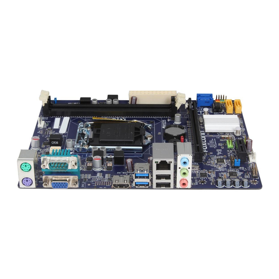
PRODUCT INTRODUCTION 1-2 Layout 1. Speaker Header 10. SATA 3.0 Connectors 2. Clear CMOS Header 11. Front Panel Header 3. PCI Express X16 Slot 12. SATA 2.0 Connectors 4. ME Header 13. 24-pin ATX Power Connector 5. Front Audio Header 14. VDDR_SEL Header 6. PCI Express X1 Slot 15. DDR3 DIMM Slots 7. SYS_FAN Header 16. CPU_FAN Header 8. Front USB 2.0 Headers 17. LGA1150 CPU Socket 9. Chipset: Intel® H81 18. 4-pin ATX 12V Power Connector The above motherboard layout is for reference only, please refer to the physical motherboard for detail. -
Page 12: Back Panel Connectors
PRODUCT INTRODUCTION 1-3 back Panel Connectors H81MXV: PS/2 Mouse Port COM Port HDMI Port LAN Port Line In Line Out Microphone In PS/2 Keyboard Port VGA Port USB 3.0 Port USB 2.0 Port Audio Port H81MXV-D: PS/2 Mouse Port COM Port DVI-D Port LAN Port Line In Line Out Microphone In PS/2 Keyboard Port VGA Port USB 3.0 Port... - Page 13 PRODUCT INTRODUCTION as an USB keyboard/mouse, USB printer, USB flash drive and etc. You need to install the USB 3.0 driver in the Driver CD before using it. 7. USb 2.0 Ports The USB port supports the USB 2.0/1.1 specification. Use this port for USB devices such as an USB keyboard/mouse, USB printer, USB flash drive and etc. 8. LAN Port The Ethernet LAN port provides Internet connection at up to 10/100/1000Mb/s data rate. Left: Active Right: Link Active Link LAN Type Status Description Status Description No Link No Link 10Mb/s Connection 1000M Green Data Green 100Mb/s Connection Blinking Activity Orange 1000Mb/s Connection 9.
-
Page 14: Chapter 2 Hardware Installation
Chapter 2 Hardware Installation This chapter introduces the hardware installation process, including the installation of the CPU, memory, power supply, slots, pin headers and the mounting of jumpers. Caution should be exercised during the instal- lation of these modules. Please refer to the motherboard layout prior to any installation and read the contents in this chapter carefully. -
Page 15: Install The Cpu And Cpu Cooler
HARDWARE INSTALLATION 2-1 Install the CPU and CPU Cooler Read the following guidelines before you begin to install the CPU : ■ Make sure that the motherboard supports the CPU. ■ Always turn off the computer and unplug the power cord from the power supply before installing the CPU to prevent hardware damage. ■ Locate the pin one of the CPU. The CPU cannot be inserted if oriented incorrectly. (Or you may locate the notches on both sides of the CPU and alignment keys on the CPU socket.) ■ Apply an even and thin layer of thermal grease on the surface of the CPU. - Page 16 HARDWARE INSTALLATION Follow the steps to install the CPU onto the CPU socket : Before installing the CPU, make sure to turn off the computer and unplug the power cord from the power outlet to prevent damage to the CPU. 1.
-
Page 17: Install The Cpu Cooler
HARDWARE INSTALLATION Install the CPU Cooler Follow the steps below to correctly install the CPU cooler on the motherboard. 1. Apply and spread an even thermal 2. Place the four bolts of the CPU grease on the surface of CPU. cooler to the holes of the motherboard, push them straight down from the top, and the bolts will be fastened on the... -
Page 18: Install The Memory
HARDWARE INSTALLATION 2-2 Install the Memory Read the following guidelines before you begin to install the memory : ■ Make sure that the motherboard supports the memory. It is recommended that memory of the same capacity, brand, speed, and chips be used, and please select Dual channel first to achieve optimum performance. ■ Always turn off the computer and unplug the power cord from the power outlet before installing the memory to prevent hardware damage. ■ Memory modules have a foolproof design. A memory module can be installed in only one direction. -
Page 19: Installing A Memory
HARDWARE INSTALLATION Installing a Memory If you take a look at front side of memory module, it has asymmetric pin counts on both sides separated by a notch in the middle, so it can only fit in one direction. Follow the steps below to correctly install your memory modules into the sockets. Notch Step 1: Spread the clips at both ends of the memory socket. Place the memory module onto the socket, then put your fingers on top edge of the module, and push it down firmly and seat it vertically into the memory socket. -
Page 20: Install An Expansion Card
HARDWARE INSTALLATION 2-3 Install an expansion Card ■ Make sure the motherboard supports the expansion card. ■ Always turn off the computer and unplug the power cord from the power outlet before installing an expansion card to prevent hardware damage. PCI Express x16 PCI Express x1 follow the steps below to correctly install your expansion card in the expansion slot. 1. Locate an expansion slot that supports your card. Remove the metal slot cover from the chassis back panel. -
Page 21: Install Other Internal Connectors
HARDWARE INSTALLATION 2-4 Install other Internal Connectors Power Connectors This motherboard uses an ATX power supply. In order not to damage any device, make sure all the devices have been installed properly before applying the power supply. 24-pin ATX Power Connector: PWR1 PWR1 is the ATX power supply connector. - Page 22 HARDWARE INSTALLATION front Panel Header: fP This motherboard includes one connector for connecting the front panel switch and LED Indicators. Hard Disk LeD Connector (HDD-LeD) Connect to the chassis front panel IDE HDD-LED PWR-LED indicator LED. It indicates the active status RESET-SW PWR-SW of the hard disks. This 2-pin connector is...
- Page 23 HARDWARE INSTALLATION Speaker Header: SPeAKeR The speaker header is used to connect speaker of the chassis. EMPTY SPKJ SPEAKER USb 2.0 Headers: f_USb1/2 These connectors comply with USB 2.0 speci- fication, you can get USB ports by connecting the USB module cable to any of these connectors. EMPTY F_USB1/2 fan Headers: CPU_fAN, SYS_fAN The fan speed can be controlled and monitored in the BIOS Setup.
-
Page 24: Jumpers
HARDWARE INSTALLATION 2-5 Jumpers For some features needed, users can change the jumper settings on this motherboard to modify them. This section explains how to use the various functions of this motherboard by changing the jumper settings. Users should read the following content carefully prior to modifying any jumper setting. - Page 25 HARDWARE INSTALLATION Intel® Me Jumper: PCH_Me_eNAbLe This motherboard uses this jumper to enable or disable Intel® Management Engine function. Intel® Management Engine (ME) is an embedded microcontroller located in Intel chipset. It provides latest IT management features such as Intel® AMT, that allows to improve manage- ment of corporate assets.
-
Page 26: Chapter 3 Bios Setup
Chapter 3 bIOS Setup This chapter tells how to change system settings through the BIOS Setup menus. Detailed descriptions of the BIOS parameters are also provided. You have to run the Setup Program when the following cases occur: 1. An error message appears on the screen during the system Power On Self Test (POST) process. -
Page 27: Enter Bios Setup
BIOS SETUP enter bIOS Setup The BIOS is the communication bridge between hardware and software, correctly setting up the BIOS parameters is critical to maintain optimal system performance. Power on the computer, when the message “Press <Del> to enter setup, Press <f7> to enter boot menu” appears at the bottom of the screen, you can press <DEL>... -
Page 28: Main
BIOS SETUP Main Aptio Setup Utility - Copyright (C) 2013 American Megatrends, Inc. Main Chipset Advanced Boot Power Health Security Exit Main Set the Date. Use Tab to BIOS Vendor American Megatrends switch between Date elements. Core Version 4.6.5.4 BIOS Date 09/09/2013 15:05:52 System Date [Fri 11/22/2013]... -
Page 29: Chipset
BIOS SETUP Chipset Aptio Setup Utility - Copyright (C) 2013 American Megatrends, Inc. Main Chipset Advanced Boot Power Health Security Exit Chipset ME Subsystem Parameters ME Configuration ▶ → ←: Select Screen ↑ ↓: Select Item Enter: Select +/-: Change Opt. F1: General Help F2: Previous Values F3: Optimized Defaults... -
Page 30: Advanced
BIOS SETUP Advanced Aptio Setup Utility - Copyright (C) 2013 American Megatrends, Inc. Main Chipset Advanced Boot Power Health Security Exit Advanced Network stack Settings Network Stack ▶ CPU Setup ▶ SATA Configuration ▶ VGA Memory ▶ System Devices Setup ▶... -
Page 31: Cpu Setup
BIOS SETUP CPU Setup Aptio Setup Utility - Copyright (C) 2013 American Megatrends, Inc. Advanced Enhanced Intel SpeedStep Technology CPU Setup EIST [Enabled] [Enabled] [Enabled] → ←: Select Screen ↑ ↓: Select Item Enter: Select +/-: Change Opt. F1: General Help F2: Previous Values F3: Optimized Defaults F4: Save &... -
Page 32: Sata Configuration
BIOS SETUP SATA Configuration Aptio Setup Utility - Copyright (C) 2013 American Megatrends, Inc. Advanced (1) IDE Mode. (2) AHCI Mode. SATA Configuration SATA Mode [IDE Mode] SATA Controller 0 [Enhanced] SATA Controller 1 [Enhanced] → ←: Select Screen ↑ ↓: Select Item Enter: Select +/-: Change Opt. -
Page 33: Vga Memory
BIOS SETUP VGA Memory Aptio Setup Utility - Copyright (C) 2013 American Megatrends, Inc. Advanced Select DVMT 5.0 Pre-Allocated VGA Memory (Fixed) Graphics Memory size used by the Internal Graphics Pre-Allocated Memory Size [32M] Device. DVMT Fixed Memory Size [256M] IGD Multi-Monitor [Disabled] →... - Page 34 BIOS SETUP ► HD Audio controller This item is used to enable or disable the Azalia HD Audio Controller. ► Onboard LAN Controller This item is used to enable or disable the onboard LAN controller ► Onboard LAN BOOT ROM This item is used to enable or disable Boot Option for Legacy Network Devices. ► All USB Devices This item is used to enable or disable all USB devices.
-
Page 35: Boot
BIOS SETUP boot Aptio Setup Utility - Copyright (C) 2013 American Megatrends, Inc. Main Chipset Advanced Power Health Security Exit Boot Boot Configuration Enables or disables Quiet Boot option Quiet Boot [Enabled] Bootup Up Num-lock [On] Boot Mode Select [UEFI and Legacy] Set Boot Priority Boot Option #1 [CD/DVD]... -
Page 36: Power
BIOS SETUP Power Aptio Setup Utility - Copyright (C) 2013 American Megatrends, Inc. Main Chipset Advanced Boot Power Health Security Exit ACPI Suspend Type [S3(STR)] Select the highest ACPI sleep state the system will enter when the SUSPEND button is pressed. Resume By Onboard LAN [Enabled] Resume By PCIE-PME... - Page 37 BIOS SETUP return to previous state when the STR function wakes. ► Resume By Onboard LAN This item is used to enable or disable the onboard LAN to generate a wake up. ► Resume By PCIE-PME This item is used to enable or disable the PCI Express device to generate a wake up. ► Resume By Alarm This item is used to enable or disable RTC alarm event to generate a wake up.
-
Page 38: Health
BIOS SETUP Health Aptio Setup Utility - Copyright (C) 2013 American Megatrends, Inc. Main Chipset Advanced Boot Power Health Health Security Exit Enable/Disable Smart Fan CPU Temperature Status : MEDIUM Function CPU Fan Speed : 3026 RPM System Temperature Status : LOW System Fan Speed : N/A... -
Page 39: Security
BIOS SETUP Security Aptio Setup Utility - Copyright (C) 2013 American Megatrends, Inc. Main Chipset Advanced Boot Power Health Security Security Exit Set Administrator Password.The Password Description password must be 1 to 20 charac- ters long. Administrator Password Not Installed User Password Not Installed Administator Password... -
Page 40: Exit
BIOS SETUP exit Aptio Setup Utility - Copyright (C) 2013 American Megatrends, Inc. Main Chipset Advanced Boot Power Health Security Exit Exit Reset the system after saving Save Changes and Exit the changes. Discard Changes and Exit Load Optimized Defaults Boot Override →... -
Page 41: Chapter 4 Cd Instruction
Chapter 4 CD Instruction The utility CD that comes with the motherboard contains useful software and several utility drivers that enhance the motherboard features. This chapter includes the following information: ■ Install driver and utility ■ FOX ONE ■ FOX LiveUpdate ■ FOX LOGO ■ FOX DMI... -
Page 42: Install Driver And Utility
Manual Installation Step by Step Automatic Installation by One Click Drop to System Tray Exit the program Visit Foxconn's Browse CD View User’s Manual Show Utilities Show Drivers website Choose the items you want to Install... -
Page 43: Install Utility
CD INSTRUCTION 2. Install Utility Use these options to install additional software programs. And click “User’s Manual“ button to view the product manual. The Driver and Utility items displayed above represent a Windows 8.1 based system. The appearance may change with different Operating Systems. -
Page 44: Fox One
CD INSTRUCTION 4-2 fOX ONe FOX ONE is a powerful utility for easily modifying system settings. It also allows users to monitor various temperature values, voltage values, frequencies and fan speeds at any time. With FOX ONE, you can : ■ Monitor hardware temperatures, voltages, frequencies and fan speeds. -
Page 45: Main Page
CD INSTRUCTION 1. Main Page Show CPU Information Toolbar Alert Lamp Switch Button Skin Button Exit Minimum Configuration Homepage Monitor Frequency/Voltage/Fan speed/Temperature value Toolbar Use the toolbar to navigate to other pages. Alert Lamp When the system is in healthy state, the color of alert lamp is green. When the system is in abnormal state, the alert lamp color is red. - Page 46 Minimum Click this button to drop the FOX ONE to Windows system tray located at the lower right corner of your screen. Homepage Click this button to visit Foxconn motherboard website : http://www.foxconnchannel.com Configuration 1). Monitor interval (ms) : This is to define the interval of different messages of system settings which are to be displayed...
- Page 47 CD INSTRUCTION 2). Simple Mode : To select which message of system settings are to be displayed in the Simple Mode. Messages such as CPU frequency, voltage...etc., they can be displayed one by one in Simple Mode. 3). F.I.S. Calibration (FOX Intelligent Stepping, Optional): This function will re-calibrate the CPU's loading, and it may take several minutes to proceed.
-
Page 48: Cpu Page - Cpu Control
CD INSTRUCTION 2. CPU Page - CPU Control This page lets you select (or overclock) CPU clock to meet the current performance level of the system. The fastest and suitable CPU clock running for current system can be calculated by FOX ONE automatically or manually input by yourselves. - Page 49 CD INSTRUCTION A message informs you to push RESET button later if the system hangs finally. Click Yes to continue. You can see the system is raising CPU clock until the system hangs. Push RESET button on the front panel of your system to restart the computer.
- Page 50 CD INSTRUCTION Now, your system is running at a CPU clock of 255MHz. FOX Intelligent Stepping (F.I.S., Optional) Select FOX Intelligent Stepping will allow your system to automatically adjust your CPU clock rate based on different system loadings. For example, if you select Power Gaming, CPU clock will be driven to run at its maximum speed.
-
Page 51: Frequency Page - Frequency Control (Optional)
CD INSTRUCTION 3. Frequency Page - Frequency Control (Optional) This page lets you set memory and PCI Express frequencies by manual. Go to Freq. page Close this page Select the option you want to set Adjust by manual Reset the changes Apply the changes 4. - Page 52 CD INSTRUCTION 4.2 Limit Setting - System Temperature This page lets you to set system high limit temperature and enable the alert function. Show current system temperature value Enable alert function when the system temperature is higher than high limit value Show current high limit value of system temperature Set high limit by dragging the lever...
- Page 53 CD INSTRUCTION 4.4 Limit Setting - System Fan This page lets you to set system fan low limit rpm and enable the alert function. Show current system fan rpm value Enable alert function when the system fan runs slower than low limit rpm value Show current low limit rpm value of system Set low limit rpm by dragging the lever...
-
Page 54: Voltage Page - Voltage Control (Optional)
CD INSTRUCTION 5. Voltage Page - Voltage Control (Optional) This page lets you set CPU voltage, memory voltage and North Bridge voltage manually. CPU voltage can be stepped up/down by a unit of 12.5mV, while memory is 0.05V/step, and North Bridge is 0.04V/step. Go to Voltage page Select the option you want to set Adjust by manual Reset the changes Apply the changes 6. -
Page 55: Fox Liveupdate
CD INSTRUCTION 4-3 FOX LiveUpdate FOX LiveUpdate is a useful utility to backup and update your system BIOS, drivers and utilities by local or online. Supporting Operating Systems : ■ Windows 7 (32-bit and 64-bit) ■ Windows 8.1 (32-bit and 64-bit) Please set the BIOS setting “BIOS Write Protect” or “Super BIOS Protect” to [Disabled] when running this application. - Page 56 CD INSTRUCTION Key in a BIOS name Click here 1-3 Local Update - Update This page helps you to update your BIOS from a local file. After click “Update”, An alert message will be displayed to ensure if you really want to continue, click “Yes” to confirm. A setup wizard will guide you to load a local BIOS file to finish the operation. You must remember from which directory to load your new BIOS file (with an extension of ".BIN" for Award BIOS, ".ROM" for AMI BIOS) before the setup wizard starts. FOX LiveUpdate can automatically backup old BIOS before update. This feature can be enabled in the "Configure-System" setup. Please refer to "Configure- System" section for more detail. The default backup directory is C:\LiveUpdate_ Temp, but the backup file name will be automatically generated. It is hard to find it out from a backup directory, and we recommend you using Explorer to check date/ time message of this backup file to find it out and write its name down to remember...
-
Page 57: Online Update
CD INSTRUCTION 2. Online Update 2-1 Online Update - Update BIOS This page lets you update your system BIOS from Internet. Click “Start”, it will search the new BIOS from Internet. Then follow the wizard to finish the update operation. Click here Current information Search new BIOS from Internet Select BIOS to update Browse detailed information Update BIOS Close the window 2-2 Online Update - Update Driver... - Page 58 CD INSTRUCTION Select the driver to update Browse detailed information Install the selected driver Close the window 2-3 Online Update - Update Utility This page lets you update utilities from Internet. Click “Start”, it will search the new utilities from Internet. Then follow the wizard to finish the update operation. Click here Current information Search new utilities from Internet Select the utility to update...
- Page 59 CD INSTRUCTION 2-4 Online Update - Update All This page lets you update your system drivers from Internet. Click “Start”, it will search all new BIOS/drivers/utilities from Internet. Then follow the wizard to finish the update operation. Click here Current information Search all new BIOS/ drivers/utilities from Internet Browse detailed BIOS information Browse detailed driver information Browse detailed utility information Close the window...
-
Page 60: Configure
CD INSTRUCTION 3. Configure 3-1 Configure - option This page lets you set auto search options. After you enable the auto search function, FOX LiveUpdate will start its searching from Internet and if any qualified item found, it will pop out a message on the task bar to inform you to do the next step. Click here Set auto search options Set auto search the latest FOX LiveUpdate... - Page 61 CD INSTRUCTION When you enable "Auto Search FOX LiveUpdate", if your FOX LiveUpdate version is older, it will auto search from internet and prompt you to install the new version. Prompt you to install the new FOX LiveUpdate 3-2 Configure - System This page lets you set the backup BIOS location and determine if the FOX LiveUpdate can auto run when the system starts up.
-
Page 62: About & Help
CD INSTRUCTION 3-3 Configure - Advance This page lets you select to flash BIOS / Boot Block. If you choose Flash Boot Block, it means BIOS is not protective, and you must make sure the flash process is continuous and without any interruption. Click here Select which BIOS ROM to flash(Only available to motherboard with backup BIOS ROM ) Select to flash Boot Block Apply the changes Reset to default value We recommend that you had better keep the default setting unchanged to avoid any damage. -
Page 63: Fox Logo
CD INSTRUCTION 4-4 fOX LOGO FOX LOGO is a simple and useful utility to backup, change and delete the boot time Logo. The boot Logo is the image that appears on screen during POST (Power-On Self-Test). You can prepare a JPG image (1024x768) file, then use FOX LOGO to open it and change the boot time Logo. Boot time Logo will be displayed if you enable the BIOS "Quiet Boot" setting in "Advanced BIOS Features"... -
Page 64: Fox Dmi
CD INSTRUCTION 4-5 fOX DMI FOX DMI is a full Desktop Management Interface viewer, and it provides three DMI data formats: Report, Data Fields and Memory Dump. With DMI information, system maker can easily analyze and troubleshoot your motherboard if there is any problem occurred.