Table of Contents
Advertisement
Advertisement
Table of Contents

Related Manuals for Foxconn H61M-S


Summary of Contents for Foxconn H61M-S
- Page 1 H61M Series Motherboard User’s Manual...
- Page 2 Statement: This manual is the intellectual property of Foxconn, Inc. Although the information in this manual may be changed or modified at any time, Foxconn does not obligate itself to inform the user of these changes. Trademark: All trademarks are the property of their respective owners.
-
Page 3: Declaration Of Conformity
HON HAI PRECISION INDUSTRY COMPANY LTD 66 , CHUNG SHAN RD., TU-CHENG INDUSTRIAL DISTRICT, TAIPEI HSIEN, TAIWAN, R.O.C. declares that the product Motherboard H61M-S/H61M is in conformity with (reference to the specification under which conformity is declared in accordance with 89/336 EEC-EMC Directive) ■... - Page 4 Declaration of conformity Trade Name: FOXCONN Model Name: H61M-S/H61M Responsible Party: PCE Industry Inc. Address: 458 E. Lambert Rd. Fullerton, CA 92835 Telephone: 714-738-8868 Facsimile: 714-738-8838 Equipment Classification: FCC Class B Subassembly Type of Product: Motherboard Manufacturer: HON HAI PRECISION INDUSTRY...
-
Page 5: Installation Precautions
Installation Precautions ■ Electrostatic discharge (ESD) is the sudden and momentary electric current that flows between two objects at different electrical potentials. Normally it comes out as a spark which will quickly damage your electronic equipment. Please wear an electrostatic discharge (ESD) wrist strap when handling components such as a motherboard, CPU or memory. -
Page 6: Table Of Contents
TAble of CoNTeNTS Chapter 1 Product Introduction Product Specifications ................2 Layout.......................4 Back Panel Connectors ................5 Chapter 2 Hardware Install Install the CPU and CPU Cooler ..............8 Install the Memory .................. 11 Install an Expansion Card ..............14 Install other Internal Connectors ............15 Jumpers ....................19 Chapter 3 bIoS Setup Main ......................23... - Page 7 Technical Support : Support Website : http://www.foxconnchannel.com Support Website : http://www.foxconnsupport.com Worldwide online contact Support : http://www.foxconnsupport.com/inquiry.aspx CPU Support list : http://www.foxconnsupport.com/cpusupportlist.aspx Memory, VGA Compatibility list : http://www.foxconnsupport.com/complist.aspx...
- Page 8 Thank you for buying Foxconn H61M/H61M-S Series motherboard. Foxconn products are engineered to maximize computing power, providing only what you need for break-through performance. With a range of connectivity features for today multi-media computing requirements, H61M-S/H61M enables you to unleash more power from your computer.
-
Page 9: Product Specifications
Storage H61 chipset: - 4 x SATA 2.0 connectors 3Gb/s data transfer rate Asmedia ASM1061: - 2 x SATA 3.0 connectors 6Gb/s data transfer rate (only for H61M-S) Realtek 8111E Gigabit LAN chip Audio Realtek ALC662 audio chip: - High Definition Audio - 2/4/5.1-channel... - Page 10 1 x VGA port 1 x DVI-D port 1 x HDMI port 6 x USB 2.0 ports(H61M) 4 x USB 2.0 ports(H61M-S) 2 x USB 3.0 ports (H61M-S) 1 x RJ-45 LAN port 3-ports Audio jacks Hardware Monitor System voltage detection...
-
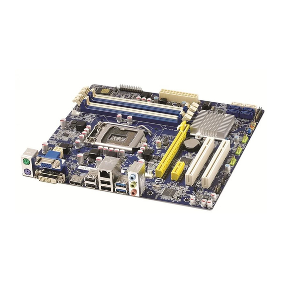
Page 11: Layout
1-2 layout 1. 4-pin ATX 12V Power Connector 12. Clear CMOS Jumper 2. SYS_FAN1 Header 13. TPM Header 3. PCI Express x16 Slot 14. SATA Connectors 15 Chipset: Intel ® H61 4. PCI Express x1 Slot 5. PCI Express Slot 16. -
Page 12: Back Panel Connectors
1-3 back Panel Connectors Back panel connectors of 5.1 channel (H61M-S): PS/2 Mouse Port VGA Port HDMI Port LAN Port Line In Line Out Microphone In PS/2 Keyboard Port USB Ports USB 3.0 Ports Audio Ports DVI-D Port (only for H61M-S) Back panel connectors of 5.1 channel (H61M):... - Page 13 Orange 1000Mb/s Connection 8. USb 3.0 Ports (only for H61M-S) The USB port supports the USB 3.0/2.0/1.1 specification. Use this port for USB devices such as an USB keyboard/mouse, USB printer, USB flash drive and etc. You need to install the USB 3.0 driver in the Driver CD before using it.
- Page 14 This chapter introduces the hardware installation process, including the installation of the CPU, memory, power supply, slots, pin headers and the mounting of jumpers. Caution should be exercised during the installation of these modules. Please refer to the motherboard layout prior to any installation and read the contents in this chapter carefully.
-
Page 15: Install The Cpu And Cpu Cooler
2-1 Install the CPU and CPU Cooler Read the following guidelines before you begin to install the CPU : ■ Make sure that the motherboard supports the CPU. ■ Always turn off the computer and unplug the power cord from the power supply before installing the CPU to prevent hardware damage. - Page 16 Follow the steps to install the CPU onto the CPU socket : Before installing the CPU, make sure to turn off the computer and unplug the power cord from the power outlet to prevent damage to the CPU. 1. Release the CPU socket lever. 2.
-
Page 17: Install The Cpu Cooler
Install the CPU Cooler Follow the steps below to correctly install the CPU cooler on the motherboard. 1. Apply and spread an even thermal 2. Place the four bolts of the CPU grease on the surface of CPU. cooler to the holes of the motherboard, push them straight down from the top, and the bolts will be fastened on the motherboard. -
Page 18: Install The Memory
2-2 Install the Memory Read the following guidelines before you begin to install the memory : ■ Make sure that the motherboard supports the memory. It is recommended that memory of the same capacity, brand, speed, and chips be used. ■... - Page 19 For this motherboard, DIMM(1,2), DIMM(3,4) are two pairs of channels. For Sandybridge CPU, in each pair of DIMM channel, you need to install blue DIMM first, then install white DIMM the second. White DIMM can not function if no blue DIMM is installed. (Please refer to the silkscreen next to the DIMM slots to identify the sequence of DIMM(1,2, 3, 4) on the motherboard.) 1.
-
Page 20: Installing A Memory
Installing a Memory Before installing a memory module, make sure to turn off the computer and unplug the power cord from the power outlet to prevent damage to the memory module. Be sure to install DDR3 DIMMs on this motherboard. Notch If you take a look at front side of memory module, it has asymmetric pin counts on both sides separated by a notch in the middle, so it can only fit in one direction. -
Page 21: Install An Expansion Card
2-3 Install an expansion Card ■ Make sure the motherboard supports the expansion card. Carefully read the manual that came with your expansion card. ■ Always turn off the computer and unplug the power cord from the power outlet before installing an expansion card to prevent hardware damage. -
Page 22: Install Other Internal Connectors
2-4 Install other Internal Connectors Power Connectors This motherboard uses an ATX power supply. In order not to damage any device, make sure all the devices have been installed properly before applying the power supply. 24-pin ATX Power Connector : PWR1 PWR1 is the ATX power supply connector. - Page 23 Audio Connector : f_AUDIo PORT1_L AUD_GND The audio connector supports HD Audio standard. It PORT1_R PRESENCEJ provides the Front Audio output choice. PORT2_R SENSE1_RETURN SENSE_SEND EMPTY PORT2_L SENSE2_RETURN F_AUDIO S/PDIf oUT Connector : SPDIf_oUT The connector is used for S/PDIF output. USb Connectors : f_USb1/2/3 In addition to the USB ports on the rear panel, this EMPTY...
- Page 24 This motherboard includes one connector for connecting the front panel switch and LED Indicators. HDD-LED PWR-LED RESET-SW PWR-SW Hard Disk leD Connector (HDD-leD) EMPTY Connect to the chassis front panel IDE indicator LED. It indicates the active status of the hard disks. This 2-pin connector is directional with +/- sign.
- Page 25 Chassis Intruder Alarm Connector : INTR The connector can be connected to a security INTRUDERJ switch on the chassis. The system can detect INTR the chassis intrusion through the function of this connector. If eventually the chassis is closed, the system will send a message out.
-
Page 26: Jumpers
2-5 Jumpers For some features needed, users can change the jumper settings on this motherboard to modify them. This section explains how to use the various functions of this motherboard by changing the jumper settings. Users should read the following content carefully prior to modifying any jumper setting. Description of Jumpers 1. - Page 27 Intel® Me Jumper: PCH_Me_eNAble This motherboard uses PCH_ME_ENABLE jumper to enable or disable Intel® Management Engine function. Intel® Management Engine (ME) is an embedded microcontroller located in Intel chipset. It provides latest IT management features such as Intel® AMT, that allows to improve management of corporate assets.
-
Page 28: Chapter 3 Bios Setup
This chapter tells how to change system settings through the BIOS Setup menus. Detailed descriptions of the BIOS param- eters are also provided. You have to run the Setup Program when the following cases occur : 1. An error message appears on the screen during the system Power On Self Test (POST) process. -
Page 29: Enter Bios Setup
enter bIoS Setup The BIOS is the communication bridge between hardware and software, correctly setting up the BIOS parameters is critical to maintain optimal system performance. Power on the computer, when the message "Press <Del> to enter Setup, <f7> to boot Menu" appears at the bottom of the screen, you can press <DEL>... -
Page 30: Main
System Date [Wed 03/23/2011] Set the Date. Use Tab to System Time [19:19:09] switch between Date elements. Access Level Administrator Model Name H61M-S/H61M ME Version 7.1.20.1119 BIOS Version B93F1D06 Build Date and Time 11/12/2011 17:48:03 Halt On [All, but keyboard] CPU Brand Name: Intel(R) Core(TM) i15-2310 CPU @ 2.90GHz... - Page 31 [All Errors]: All errors can result in system halt. [No Errors]: No error can result in system halt. [All, but keyboard]: All errors but keyboard can result in system halt. ► CPU Brand Name It displays the current CPU name. ►...
-
Page 32: F-Center
f-Center Aptio Setup Utility - Copyright (C) 2011 American Megatrends, Inc. Main Advan Advanced Boot Power Health Security Exit F-Center Fox Control Center Super BIOS Protection Settings Super BIOS Protect [Disabled] ▶ Smart BIOS ▶ Fox Intelligent Stepping ▶ CPU Configuration ▶... -
Page 33: Fox Intelligent Stepping
► Smart Power LED Smart Power LED is a feature built on your motherboard to indicate different states during Power-On Self-Test (POST). The LED is located at the front panel, and it displays POST state by different long-short blinking intervals. You can always leave this state enabled. ►... -
Page 34: Cpu Configuration
CPU Configuration Aptio Setup Utility - Copyright (C) 2011 American Megatrends, Inc. F-Center CPU Configuration Intel AES-NI CPU Brand Name: Intel(R) Core(TM) i5-2310 CPU @ 2.90GHz L1 Date Cache 32 kB X 4 L1 Code Cache 32 kB X 4 L2 Cache 256 kB X 4 L3 Cache... -
Page 35: Performance Tuning
► CPU C6 state This item is used to enable or disable CPU C6 state to OS. ► Package C State limit It is used to select the C-State mode. ► Hyper-Threading This item is used to enable or disable the Hyper-Threading Technology feature. Performance Tuning Aptio Setup Utility - Copyright (C) 2011 American Megatrends, Inc. - Page 36 North Bridge Configuration ► Memory Multiplier This item is used to adjust the memory Clock Ratio. The available settimgs are: [10.67], [13.33], [16], [18.67], [21.33]. ► CAS# Latency(tCL) This item dispalys the CAS Latency time. The CAS Latency is the number of clock cycles that elapse from the time the request for data is sent to the actual memory location until the data is transmitted from the module.
-
Page 37: Advanced
Advanced Aptio Setup Utility - Copyright (C) 2011 American Megatrends, Inc. Main F-Center Advanced Boot Power Health Security Exit Advanced ▶ North Brigde North Brigde Parameters ▶ ME Subsystem ▶ Onboard Device Configuration ▶ SATA Configuration ▶ Super IO Configuration ▶... -
Page 38: Integrated Graphics
► Memory Slot 0/1/2/3 These items display the memory size installed on each slot. ► Integrated Graphics This item is used to set the mode of the Integrated Graphics. ► Initial Graphic Adapter This item is used to select which graphics controller is used as the primary boot device. ►... -
Page 39: Onboard Device Configuration
[Enabled]: This option will enable the legacy USB support. [Disabled]: This option will keep USB devices available only for EFI applications. ► USB3.0 Support (only for H61M-S) This item is used to enable or disable USB3.0 Support. ► Azalia HD Audio controller This item is enable oe disable the Azalia HD Audio Controller. -
Page 40: Sata Configuration
SATA Configuration Aptio Setup Utility - Copyright (C) 2011 American Megatrends, Inc. Advanced SATA Configuration SATA Ports Device Names if Present and Enabled. Onboard SATA Controller [Enabled] Onboard SATA Mode [Native IDE] Serial-ATA Controller 0 [Compatible] Serial-ATA Controller 1 [Enhanced] ▶... -
Page 41: Super Io Configuration
Super IO Configuration Aptio Setup Utility - Copyright (C) 2011 American Megatrends, Inc. Advanced Set Parameters of Serial Port Super IO Configuration 0 (COMA) Super IO Chip IT8728 ▶ Serial Port 0 Configuration ▶ Parallel Port Configuration → ←: Select Screen ↑... -
Page 42: Trusted Computing
Trusted Computing Aptio Setup Utility - Copyright (C) 2011 American Megatrends, Inc. Advanced Enable or Disables TPM support. TPM Configuration O.S. will not show TPM. Reset TPM SUPPORT [Disable] of platform is required. Current TPM Status Information NO TPM Hardware →... -
Page 43: Boot
boot Aptio Setup Utility - Copyright (C) 2011 American Megatrends, Inc. Main F-Center Advanced Boot Boot Power Health Security Exit Boot Configuration North Brigde Parameters Bootup Numlock State [On] Quiet Boot [Enabled] Interrupt 19 Capture [Enabled] Boot Option Priorities → ←: Select Screen ↑... -
Page 44: Power
Power Aptio Setup Utility - Copyright (C) 2011 American Megatrends, Inc. Main F-Center Advanced Boot Power Power Health Security Exit ACPI Sleep State [S3] Select the highest ACPI sleep Resume By PS2 KB/Mouse [Enabled] state the system will enter Resume By USB Device(s) [Enabled] when the SUSPEND button is Resume By PCIE Device(s) - Page 45 ► Restore AC Power Loss This item is used to set which state the PC will take with when it resumes after an AC power loss.
-
Page 46: Health
Health Aptio Setup Utility - Copyright (C) 2011 American Megatrends, Inc. Main F-Center Advanced Boot Power Health Security Exit Health Case Open Warning [Disabled] Enabled Case Open Warning and open chassis,Intrusion Alarm CPU Temperature : +98 C will appear. If don’t enter System Temperature : +34 C bios setup and disabled Case... -
Page 47: Security
Security Aptio Setup Utility - Copyright (C) 2011 American Megatrends, Inc. Main F-Center Advanced Boot Power Health Security Exit Security Set Administrator Password. Password Description If only the Administrator’s password is set,then this only limits access to Setup and is only asked for when entering Administrator Password Not Installed... -
Page 48: Exit
exit Aptio Setup Utility - Copyright (C) 2011 American Megatrends, Inc. Main F-Center Advanced Boot Power Health Security Exit Exit Reset system setup after saving Save Changes and Reset the changes. Discard Changes and Reset Restore Defaults Boot Override → ←: Select Screen ↑... - Page 49 The utility CD that came with the motherboard contains useful software and several utility drivers that enhance the motherboard features. This chapter includes the following information: ■ Install driver and utility ■ FOX ONE ■ FOX LiveUpdate ■ FOX LOGO ■...
-
Page 50: Install Driver And Utility
Manual Installation Step by Step Automatic Installation by One Click Drop to System Tray Exit the program View the User’s Visit Foxconn's Show Utilities Show Drivers Browse CD Website Manual Choose the items you want to Install... - Page 51 2. Utility Use these options to install additional software programs. And click “User’s manual” button to view the utility (FOX ONE, FOX LiveUpdate, FOX LOGO, FOX DMI) help manual. Click here The Driver and Utility items displayed above represent a Windows 7 based system. The appearance may change with different Operating Systems.
-
Page 52: Fox One
foX oNe FOX ONE is a powerful utility for easily modifying system settings. It also allows users to monitor various temperature values, voltage values, frequencies and fan speeds at any time. With FOX ONE, you can : ■ Modify system performance settings, such as the CPU and memory bus speeds, CPU voltages, fan speeds, and other system performance options. -
Page 53: Main Page
1. Main Page Show CPU Toolbar Information Alert Lamp Switch Button Skin Button Exit Minimum Configuration Homepage Monitor Frequency/Voltage/Fan speed/Temperature value Toolbar Use the toolbar to navigate to other pages. Alert lamp When the system is in healthy state, the color of alert lamp is green. When the system is in abnormal state, the alert lamp color is red. - Page 54 Click this button to exit the program. Minimum Click this button to drop the FOX ONE to Windows system tray located at the lower right corner of your screen. Homepage Click this button to visit Foxconn motherboard website : http://www.foxconnchannel.com...
- Page 55 Configuration This menu allows you to configure : 1). Monitor interval (ms) : This is to define the interval of different messages of system settings which are to be displayed on Simple Mode screen. Minimum value is 1 second. 2). Simple Mode : To select which message of system settings are to be displayed in the Simple Mode.
- Page 56 Step 1 : Click Calibration icon, a message pops out to ask for continue. Select Yes. Step 2 : After data is collected, it will ask you to restart your computer now. Later on, when the FOX ONE program is activated, and F.I.S. feature (in CPU Page) is also enabled, FOX ONE will automatically adjust your CPU clock according to your system loadings.
-
Page 57: Cpu Control
2. CPU Page - CPU Control This page lets you select (or overclock) CPU clock to meet the current performance level of the system. The fastest and suitable CPU clock running for current system can be calculated by FOX ONE automatically or manually input by yourselves. Manual : You can press the up/down button to adjust your CPU clock. - Page 58 You can see the system is raising CPU clock until the system hangs. Push RESET button on the front panel of your system to restart the computer. Run FOX ONE program again, it will inform you the previous test found that 255MHz is the recommended CPU clock for your system.
-
Page 59: Frequency Control
FOX Intelligent Stepping (F.I.S., Optional) Select FOX Intelligent Stepping will allow your system to automatically adjust your CPU clock rate based on different system loadings. For example, if you select Power Gaming, CPU clock will be driven to run at its maximum speed. While in Energy Saving, CPU will lower down its speed to a minimum. -
Page 60: Limit Setting
4. Limit Setting 4.1 Limit Setting - CPU Temperature This page lets you to set CPU high limit temperature and enable the alert function. Go to Limit Show current CPU Setting page temperature value Enable alert function when the CPU temperature is higher than high limit value Show current high... - Page 61 4.3 Limit Setting - CPU Fan This page lets you to set CPU fan low limit rpm and enable the alert function. Show current CPU fan rpm value Enable alert function when the CPU fan runs slower than the low limit rpm value Show current low limit rpm value of CPU fan...
-
Page 62: Voltage Control
4.5 Limit Setting - FAN1 Fan This page lets you to set FAN1 fan low limit rpm and enable the alert function. Show current FAN1 fan rpm value Enable alert function when the FAN1 fan runs slower than low limit rpm value Show current low limit rpm value of FAN1 fan Set low limit rpm by... -
Page 63: Fan Control
6. Fan Page - Fan Control This page lets you enable Smart Fan function or set the fan speed by manual. When Smart Fan is selected, you must use a 4-pin CPU cooler in your system. Go to Fan page Enable or disable smart fan function Set fan speed by... -
Page 64: Fox Liveupdate
FOX LiveUpdate FOX LiveUpdate is a useful utility to backup and update your system BIOS, drivers and utilities by local or online. Supporting Operating Systems : ■ Windows 2000 ■ Windows XP (32-bit and 64-bit) ■ Windows 2003 (32-bit and 64-bit) ■... - Page 65 1-2 local Update - backup This page can backup your system BIOS. You can click “Backup”, and key in a file name, then click “Save” to finish the backup operation. The extension of this backup file is ".BIN" for Award BIOS and ".ROM"...
-
Page 66: Online Update
2. online Update 2-1 online Update - Update bIoS This page lets you update your system BIOS from Internet. Click “start”, it will search the new BIOS from Internet. Then follow the wizard to finish the update operation. Click here Current information Search new BIOS from Internet... - Page 67 Select the driver to update Browse detailed information Install the selected driver Close the window 2-3 online Update - Update Utility This page lets you update utilities from Internet. Click “start”, it will search the new utilities from Internet. Then follow the wizard to finish the update operation. Click here Current information Search new utilities...
- Page 68 2-4 online Update - Update All This page lets you update your system drivers from Internet. Click “start”, it will search all new BIOS/drivers/utilities from Internet. Then follow the wizard to finish the update operation. Click here Current information Search all new BIOS/ drivers/utilities from Internet Browse detailed...
-
Page 69: Configure
3. Configure 3-1 Configure - option This page lets you set auto search options. After you enable the auto search function, FOX LiveUpdate will start its searching from Internet and if any qualified item found, it will pop out a message on the task bar to inform you to do the next step. - Page 70 When you enable "Auto Search FOX LiveUpdate", if your FOX LiveUpdate version is older, it will auto search from internet and prompt you to install the new version. Prompt you to install the new FOX LiveUpdate 3-2 Configure - System This page lets you set the location of download files and auto backup BIOS, determine if the FOX LiveUpdate can auto run when the system starts up.
-
Page 71: About & Help
3-3 Configure - Advance This page lets you select to flash BIOS / Boot Block and clear CMOS. If you choose Flash Boot Block, it means BIOS is not protective, and you must make sure the flash process is continuous and without any interruption. -
Page 72: Fox Logo
foX loGo FOX LOGO is a simple and useful utility to backup, change and delete the boot time Logo. The boot Logo is the image that appears on screen during POST (Power-On Self-Test). You can prepare a JPG image (1024x768) file, then use FOX LOGO to open it and change the boot time Logo. -
Page 73: Fox Dmi
foX DMI FOX DMI is a full Desktop Management Interface viewer, and it provides three DMI data formats : Report, Data Fields and Memory Dump. With DMI information, system maker can easily analyze and troubleshoot your mother- board if there is any problem occurred. Supporting Operating Systems : ■...