Table of Contents
Advertisement
Quick Links
Advertisement
Table of Contents

Related Manuals for Multitech MultiConnect Cell MTC-H5


Summary of Contents for Multitech MultiConnect Cell MTC-H5
- Page 1 ® MultiConnect Cell MTC-H5 User Guide...
- Page 2 Legal Notices The MultiTech products are not designed, manufactured or intended for use, and should not be used, or sold or re-sold for use, in connection with applications requiring fail-safe performance or in applications where the failure of the products would reasonably be expected to result in personal injury or death, significant property damage, or serious physical or environmental damage.
-
Page 3: Table Of Contents
CONTENTS Contents Product Overview ..............................5 About the MultiConnect Cell Modem........................... 5 Documentation ................................5 Descriptions of LEDs..............................5 Side Panels ..................................6 Specifications ................................7 RS-232 9-Pin Female Connector ........................... 8 Power Draw MTC-H5 ..............................10 Dimensions.................................. 11 Serial..................................11 USB.................................... - Page 4 CONTENTS Device Phone Number ..............................20 Using Linux ................................21 Shell Commands................................21 Testing Serial Ports..............................21 Create a PPP Connection ............................21 Example..................................21 Configuring and Communicating with Your Device....................23 Interacting with Your Device Overview ........................23 Before You Begin................................. 23 Using Command Mode and Online Data Mode......................
-
Page 5: Product Overview
They are available with RS- 232 and USB connectors. The MultiConnect Cell cellular modems are based on industry-standard open interfaces. Documentation The following documentation is available on the Multi-Tech Installation Resources website at www.multitech.com/setup/product.go. Document Description MultiConnect Cell User This document. -
Page 6: Side Panels
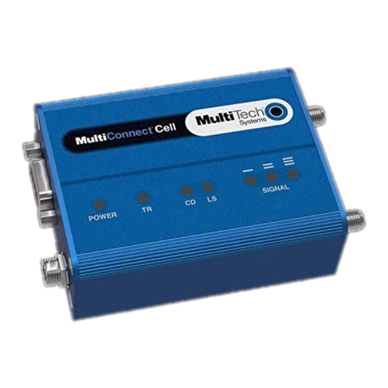
PRODUCT OVERVIEW ■ The tables that follow provide details about what the LEDs indicate. Power Not lit DC power not present. DC power present. TR (Terminal Ready) Not Lit Data is not being transmitted. Blinks when data is being transmitted. CD (Carrier Detect) Not lit Data connection is not established. -
Page 7: Specifications
PRODUCT OVERVIEW Note: The power-saving switch—which appears with the NORMAL and LOW POWER labels—is included only on models that have a serial connector. Specifications MTC-H5 Category Description General Performance HSPA+ GPRS/EDGE Cell 850 824 - 894 MHz Frequency Bands Cell 900 880 -960 MHz Cell 1800 1710 - 1880 MHz Cell 1900 1850 - 1990 MHz Radio... -
Page 8: Rs-232 9-Pin Female Connector
PRODUCT OVERVIEW Category Description Voltage Models with serial connector: 7 V to 32 V DC Models with USB connector: 5 DC Physical Description Dimensions Dimensions are shown in the section “Dimensions” that follows. Weight 8.2 ounces or 230 grams Environment Operating Temperature -40°... - Page 9 PRODUCT OVERVIEW Abbreviation Description In/Out Transmit Data Terminal Ready Ground Data Set Ready Request to Send Clear to Send Ring Indicator ® MultiConnect Cell MTC-H5 User Guide...
-
Page 10: Power Draw Mtc-H5
PRODUCT OVERVIEW Power Draw MTC-H5 5 volts Cellular call box Average measured TX Pulse (AVG) Total inrush charge connection no data current (amps) at Amplitude Current measured in (amps) maximum power (amps) MilliCoulombs (mC) GSM850Mhz 0.044 0.263 1.17 1.65 HSDPA1800Mhz 0.041 0.477 0.532... -
Page 11: Dimensions
PRODUCT OVERVIEW Dimensions Serial ® MultiConnect Cell MTC-H5 User Guide... -
Page 12: Usb
PRODUCT OVERVIEW ® MultiConnect Cell MTC-H5 User Guide... -
Page 13: Safety Warnings
SAFETY WARNINGS Safety Warnings Radio Frequency (RF) Safety Due to the possibility of radio frequency (RF) interference, it is important that you follow any special regulations regarding the use of radio equipment. Follow the safety advice given below. ■ Operating your device close to other electronic equipment may cause interference if the equipment is inadequately protected. -
Page 14: Hazardous Locations Warnings
SAFETY WARNINGS Hazardous Locations Warnings Class I, Division 2, Groups A, B, C, and D Hazardous Locations (US and Canada) ANSI_ISA_12.12.01_2013 and CSA C22.2 No. 213 -HZ models only The MTC modem is a OPEN-TYPE device and is intended for installation into a IP54 style enclosure. The enclosure would only allow access to the modem via a key or tool. -
Page 15: Antenna
SAFETY WARNINGS ■ The device is intended to be powered by a Certified SELV non-energy hazardous power supply. Antenna The antenna intended for use with this unit meets the requirements for mobile operating configurations and for fixed mounted operations, as defined in 2.1091 and 1.1307 of the FCC rules for satisfying RF exposure compliance. If an alternate antenna is used, consult user documentation for required antenna specifications. -
Page 16: Installing And Using The Device
INSTALLING AND USING THE DEVICE Installing and Using the Device Installing the Device Connect a suitable antenna to the antenna connector. If you are using the serial version of this device: Connect the DB9 male connector (9-pin) of the RS-232 cable to the RS-232 connector on the device, then connect the other end to the serial port on the other desired device. -
Page 17: Usb Cable Recommendations
INSTALLING AND USING THE DEVICE To have the device enter sleep mode, set DTR to inactive (off) on the RS-232 interface. The clear to send (CTS) signal is off when the device is in sleep mode. USB Cable Recommendations If your device has a USB connector, to avoid enumeration or power issues: ■... -
Page 18: Using Diversity
INSTALLING AND USING THE DEVICE To secure the rod to the desired surface, place and tighten two screws in the holes on either end of the mounting rod. The dimensions illustration in this guide shows the mounting rod, as well as the dimensions for placement of the screws. -
Page 19: Antenna And Activation Information
ANTENNA AND ACTIVATION INFORMATION Antenna and Activation Information Cellular Antenna Information Authorized Antenna/Antenna Specifications for Cellular Bands The cellular radio portion of the device is approved with the following antenna or for alternate antennas meeting the given specifications. Manufacturer: Laird Technologies. Description: HEPTA-SM Model Number:... -
Page 20: Account Activation For Cellular Devices
Each service provider has its own process for adding devices to their network. To find activation steps for your device: Go to http://www.multitech.com/support. Select your device. Scroll to Activation and click Download. -
Page 21: Using Linux
USING LINUX Using Linux Shell Commands Testing Serial Ports To test the serial ports created by the driver, type in a shell: # cat /dev/ttyACM0 & # echo –en "ATE0\r" > /dev/ttyACM03 # echo –en "AT\r" > /dev/ttyACM0 Note: Sending ATE0 is required, to avoid issues in the terminal output. It prevents the sending/receiving spurious characters to/from the modem when used with the Linux commands “echo”... - Page 22 USING LINUX # If you want to use the HSDPA link as your gateway defaultroute # pppd must not propose any IP address to the peer #noipdefault ipcp-accept-local ipcp-accept-remote # Keep modem up even if connection fails #persist # Hardware flow control crtscts # Ask the peer for up to 2 DNS server addresses usepeerdns...
-
Page 23: Configuring And Communicating With Your Device
CONFIGURING AND COMMUNICATING WITH YOUR DEVICE Configuring and Communicating with Your Device Interacting with Your Device Overview This section describes how to use AT commands to interact with your device. Using terminal software such as Kermit, you can issue AT commands to communicate with and configure your modem. The AT commands let you establish, read and modify device parameters and help you control how the device operates. -
Page 24: Verifying Signal Strength
CONFIGURING AND COMMUNICATING WITH YOUR DEVICE ■ Type AT and press Enter. If the device responds with OK, you are communicating with the device. Verifying Signal Strength To verify the device signal strength, enter: AT+CSQ The command indicates signal quality, in the form: +CSQ: <rssi>,<ber>... -
Page 25: Checking Network Registration
CONFIGURING AND COMMUNICATING WITH YOUR DEVICE Checking Network Registration Before establishing a packet data connection, verify the is device registered on the network. To do this enter the network registration report read command: AT+CREG? If the device returns: +CREG: 0,1 The device is registered. -
Page 26: Configuring Device As Udp Client To Connect To Udp Server
CONFIGURING AND COMMUNICATING WITH YOUR DEVICE Check signal strength. Enter: AT+CSQ Verify device is registered on the cellular network. Enter: AT!STATUS Configure socket parameters Enter: AT#SCFG=1,1,300,240,600,50 Activate context one Enter: AT#SGACT=1,1 Set firewall rule to accept connections: AT#FRWL=1,"###.##.###.#","###.##.###.#" where ###.##.###.# represents the IP range. For example: AT#FRWL=1,"204.26.122.1","204.26.122.255"... -
Page 27: Configuring Device As Udp Listener To Accept Udp Client Connections
CONFIGURING AND COMMUNICATING WITH YOUR DEVICE Enter: AT+CSQ Verify device is registered on the cellular network. Enter: AT!STATUS Configure socket parameters Enter: AT#SCFG=1,1,300,240,600,50 Activate context one Enter: AT#SGACT=1,1 Create UDP connection to Server port Enter: AT#SD=1,1,####,"###.##.###.##" where #### is the server port and ###.##.###.## is the IP number. The device responds with OK, which indicates a successful connection. -
Page 28: Transferring Ftp File To Ftp Server
CONFIGURING AND COMMUNICATING WITH YOUR DEVICE AT#FRWL=1,"###.##.###.#","###.##.###.#" where ###.##.###.# represents the IP range. For example: AT#FRWL=1,"204.26.122.1","204.26.122.255" Set connection ID 1 for UDP listening mode on port 7000. Enter: AT#SLUDP=1,1,7000 The device responds with and unsolicited indication that a host is trying to connect to connection ID 1 on port 7000. -
Page 29: Downloading File From Ftp Server
CONFIGURING AND COMMUNICATING WITH YOUR DEVICE AT#FTPTYPE=# where # is 0 for binary or 1 for ASCII. Enter the file name to be sent to the FTP server and initiate connection. Enter: AT#FTPPUT="file.txt" The device responds with: CONNECT Send the file through the device. Closing the FTP Data Connection When you finish sending the file: Enter the escape sequence. -
Page 30: Reading, Writing And Deleting Messages
CONFIGURING AND COMMUNICATING WITH YOUR DEVICE If required, change the working directory to "folder1". Enter: AT#FTPCWD="folder1" Enter the file name. Enter: AT#FTPGET="filename.txt" where filename.txt is the file you want to download. The device responds with: CONNECT The file is received through the device. The device responds with: NO CARRIER The data connection closes automatically when the file sending ends. -
Page 31: Deleting Messages
CONFIGURING AND COMMUNICATING WITH YOUR DEVICE Enter the recipient's number and your message. Enter: AT+CMGS="##########" >Your message here where ########## is the recipient's number. Send the message. Enter CTRL+Z. The device responds: +CMGS: 255 For example: AT+CMGF=1 AT+CMGS="6155554563" > How are you? <CTRL+Z to send> +CMGS: 255 Deleting Messages To delete one text message, enter:... -
Page 32: Regulatory Information
REGULATORY INFORMATION Regulatory Information Industry Canada Class B Notice This Class B digital apparatus meets all requirements of the Canadian Interference-Causing Equipment Regulations. Cet appareil numérique de la classe B respecte toutes les exigences du Reglement Canadien sur le matériel brouilleur. -
Page 33: Fcc Interference Notice
REGULATORY INFORMATION ■ Connect the equipment into an outlet on a circuit different from that to which the receiver is connected. ■ Consult the dealer or an experienced radio/TV technician for help. Warning: Changes or modifications to this unit not expressly approved by the party responsible for compliance could void the user’s authority to operate the equipment. -
Page 34: Restriction Of The Use Of Hazardous Substances (Rohs)
2011/65/EU of the European Parliament (Restriction of the use of certain Hazardous Substances in electrical and electronic equipment - RoHS). These MultiTech products do not contain the following banned chemicals ■ Lead, [Pb] < 1000 PPM ■... -
Page 35: Reach Statement
Substances) complements the WEEE Directive by banning the presence of specific hazardous substances in the products at the design phase. The WEEE Directive covers all MultiTech products imported into the EU as of August 13, 2005. EU-based manufacturers, distributors, retailers and importers are obliged to finance the costs of recovery from municipal collection points, reuse, and recycling of specified percentages per the WEEE requirements. -
Page 36: Information On Hs/Ts Substances According To Chinese Standards
REGULATORY INFORMATION Information on HS/TS Substances According to Chinese Standards In accordance with China's Administrative Measures on the Control of Pollution Caused by Electronic Information Products (EIP) # 39, also known as China RoHS, the following information is provided regarding the names and concentration levels of Toxic Substances (TS) or Hazardous Substances (HS) which may be contained in Multi-Tech Systems Inc. -
Page 37: Information On Hs/Ts Substances According To Chinese Standards (In Chinese)
REGULATORY INFORMATION Information on HS/TS Substances According to Chinese Standards (in Chinese) 依 依 照 照 中 中 国 国 标 标 准 准 的 的 有 有 毒 毒 有 有 害 害 物 物 质 质 信 信 息 息 根据中华人民共和国信息产业部...