Advertisement
Table of Contents
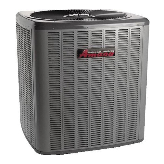
Split System Heat Pumps
•
Refer to Service Manual RS6200006 for installation, operation, and troubleshooting information.
•
All safety information must be followed as provided in the Service Manual.
•
Refer to the appropriate Parts Catalog for part number information.
•
Models listed on page 3.
This manual is to be used by qualified, professionally trained HVAC technicians only.
Goodman does not assume any responsibility for property damage or personal injury due to
improper service procedures or services performed by an unqualified person.
is a registered trademark of Maytag Corporation or its related companies and is used under
license to Goodman Company, L.P., Houston, TX. All rights reserved.
TECHNICAL MANU
TECHNICAL MANU
TECHNICAL MANU AL
TECHNICAL MANU
TECHNICAL MANU
®
ASZ 14 SEER
Copyright © 2006 - 2012, 2014 Goodman
Company, L.P.
AL
AL
AL
AL
RT6213006r12
April 2014
Advertisement
Table of Contents

Related Manuals for Amana ASZ 14 SEER


Summary of Contents for Amana ASZ 14 SEER
- Page 1 TECHNICAL MANU TECHNICAL MANU AL TECHNICAL MANU TECHNICAL MANU ® ASZ 14 SEER Split System Heat Pumps • Refer to Service Manual RS6200006 for installation, operation, and troubleshooting information. • All safety information must be followed as provided in the Service Manual.
- Page 2 PRODUCT IDENTIFICATION The model number is used for positive identification of component parts used in manufacturing. Please use this number when requesting service or parts information. BRAND: MINOR A: Amana® REVIS ION: Brand A : Initial Release SEER: SEER Rating...
- Page 3 PRODUCT IDENTIFICATION The model number is used for positive identification of component parts used in manufacturing. Please use this number when requesting service or parts information. ASZ140181A* ASZ140241A* ASZ140301A* ASZ140361A* ASZ140381A* ASZ140421A* ASZ140481A* ASZ140601A* ASZ140361B* * Indicates minor revision & is not used for order entry or inventory management The United States Environmental Protection Agency (“EPA”) has issued various regulations re- WARNING WARNING...
-
Page 4: Product Design
PRODUCT DESIGN ASZ14 models are available in 1 1/2 through 5 ton sizes and These clearances will help avoid air recirculation. If installing two or more units at the same location, allow at least 24 use R-410A refrigerant. They are designed for 208/230 volt inches between units. - Page 5 HEAT PUMP SPECIFICATIONS ASZ140[18,30,36,38]1AA-AF; ASZ140241AA-AG; ASZ140[42,48,60]1AA-AE Cooling Capacity, BTUH 18,000 24,000 30,000 36,000 36,000 42,000 48,000 60,000 Compressor R.L. Amps 12.8 14.1 16.7 14.10 17.9 19.9 26.4 L.R. Amps 48.0 58.3 73.0 79.0 77.0 112.0 109.0 134.0 Low Pressure Switch Open 22 PSIG 22 PSIG...
- Page 6 HEAT PUMP SPECIFICATIONS ASZ140181A* (G & UP); - ASZ140421A* (H & UP); ASZ140301A* (G & UP); ASZ140361A* (G & UP); ASZ140421A* (F & UP) Cooling Capacity, BTUH 18,000 24,000 30,000 36,000 42,000 Compressor R.L. Amps 12.8 14.1 16.7 17.9 L.R. Amps 48.0 58.3 73.0...
- Page 7 HEAT PUMP SPECIFICATIONS ASZ14048-601AF; ASZ140481 (G & UP); ASZ140601A* (F & UP) Cooling Capacity, BTUH 48,000 48,000 60,000 Compressor R.L. Amps 19.9 19.9 26.4 L.R. Amps 109.0 109.0 134.0 Low Pressure Switch Open 22 PSIG 22 PSIG 22 PSIG Close 50 PSIG 50 PSIG 50 PSIG...
- Page 8 HEAT PUMP SPECIFICATIONS ASZ140361B* Cooling Capacity, BTUH 35,000 36,000 Compressor R.L. Amps 14.1 16.7 L.R. Amps 77.0 79.0 Low Pressure Switch Open 22 PSIG 22 PSIG Close 50 PSIG 50 PSIG High Pressure Switch Open 610 PSIG 610 PSIG Close 420 PSIG 420 PSIG Condenser Fan Motor...
- Page 9 COOLING PERFORMANCE DATA ASZ140181A*...
- Page 10 COOLING PERFORMANCE DATA ASZ140181A*...
- Page 11 COOLING PERFORMANCE DATA ASZ140241A*...
- Page 12 COOLING PERFORMANCE DATA ASZ140241A*...
- Page 13 COOLING PERFORMANCE DATA ASZ140301A*...
- Page 14 COOLING PERFORMANCE DATA ASZ140301A*...
- Page 15 COOLING PERFORMANCE DATA ASZ140361A*...
- Page 16 COOLING PERFORMANCE DATA ASZ140361A*...
- Page 17 COOLING PERFORMANCE DATA ASZ140381A*...
- Page 18 COOLING PERFORMANCE DATA ASZ140381A*...
- Page 19 COOLING PERFORMANCE DATA ASZ140421A*...
- Page 20 COOLING PERFORMANCE DATA ASZ140421A*...
- Page 21 COOLING PERFORMANCE DATA ASZ140481A*...
- Page 22 COOLING PERFORMANCE DATA ASZ140481A*...
- Page 23 COOLING PERFORMANCE DATA ASZ140601A*...
- Page 24 COOLING PERFORMANCE DATA ASZ140601A*...
- Page 25 COOLING PERFORMANCE DATA ASZ140361B*...
- Page 26 COOLING PERFORMANCE DATA ASZ140361B*...
-
Page 27: Performance Data
PERFORMANCE DATA Model: ASZ140241A* / CA*F3636*6A*+TXV / MBR800**-1 Model: ASZ140181A* / CA*F3131*6A*+TXV / MBR800**-1 Conditions: 80° IDB, 67° IWB @ 850 CFM Conditions: 80° IDB, 67° IWB @ 600 CFM Outdoor Total Sensible Latent Total Outdoor Total Sensible Latent Total Temp. - Page 28 PERFORMANCE DATA Model: ASZ140421A* / CA*F4860*6A*+TXV / MBR2000**-1 Model: ASZ140481A* / CA*F4860*6A*+TXV / MBR2000**-1 Conditions: 80° IDB, 67° IWB @ 1400 CFM Conditions: 80° IDB, 67° IWB @ 1550 CFM Outdoor Total Sensible Latent Total Outdoor Total Sensible Latent Total Temp.
- Page 29 SPLIT SYSTEM PERFORMANCE DATA...
- Page 30 SPLIT SYSTEM PERFORMANCE DATA...
- Page 31 SPLIT SYSTEM PERFORMANCE DATA...
- Page 32 SPLIT SYSTEM PERFORMANCE DATA...
- Page 33 SPLIT SYSTEM PERFORMANCE DATA...
- Page 34 SPLIT SYSTEM PERFORMANCE DATA...
- Page 35 SPLIT SYSTEM PERFORMANCE DATA...
- Page 36 SPLIT SYSTEM PERFORMANCE DATA...
- Page 37 SPLIT SYSTEM PERFORMANCE DATA...
-
Page 38: Heating Specifications
HEATING SPECIFICATIONS Model: ASZ140181A* / CA*F3131*6A*+TXV / MBR800**-1 Model: ASZ140241A* / CA*F3636*6A*+TXV / MBR800**-1 Conditions: 600 CFM Indoor Air @ 70°F DB Conditions: 850 CFM Indoor Air @ 70°F DB Basic Unit without Capacity of Unit* Basic Unit without Capacity of Unit* Outdoor Outdoor Auxiliary Heat... - Page 39 HEATING SPECIFICATIONS Model: ASZ140481A* / CA*F4860*6A*+TXV / MBR2000**-1 Model: ASZ140421A* / CA*F4860*6A*+TXV / MBR2000**-1 Conditions: 1400 CFM Indoor Air @ 70°F DB Conditions: 1550 CFM Indoor Air @ 70°F DB Basic Unit without Capacity of Unit* Basic Unit without Capacity of Unit* Outdoor Auxiliary Heat With KW of Auxiliary heat...
- Page 40 PERFORMANCE DATA PERFORMANCE TEST All data based upon listed indoor dry bulb temperature. .00 inches external static pressure on coil of outdoor section. Indoor air cubic feet per minute (CFM) as listed in the Performance Data Sheets: If conditions vary from this, results will change as follows: 1.
- Page 41 ASZ140[18, 30-36]1AA-AF WIRING DIAGRAMS ASZ14030241AA-AG, [042-060]1AA-AE HIGH VOLTAGE! DISCONNECT ALL POWER BEFORE SERVICING OR INSTALLING THIS UNIT. MULTIPLE POWER SOURCES MAY BE PRESENT. FAILURE TO DO SO MAY CAUSE PROPERTY DAMAGE, PERSONAL INJURY OR DEATH. Wiring is subject to change, always refer to the wiring diagram on the unit for the most up-to-date wiring.
- Page 42 ASZ140[18, 30, 36]1AG/AH WIRING DIAGRAMS ASZ140241AH; [42, 48, 60]1AF/AG ASZ140361B* HIGH VOLTAGE! DISCONNECT ALL POWER BEFORE SERVICING OR INSTALLING THIS UNIT. MULTIPLE POWER SOURCES MAY BE PRESENT. FAILURE TO DO SO MAY CAUSE PROPERTY DAMAGE, PERSONAL INJURY OR DEATH. Wiring is subject to change, always refer to the wiring diagram on the unit for the most up-to-date wiring.
-
Page 43: Wiring Diagrams
ASZ140[18, 30, 36]1A[G/H] WIRING DIAGRAMS ASZ140241AJ; [42, 48, 60]1AG ASZ140361BA HIGH VOLTAGE! DISCONNECT ALL POWER BEFORE SERVICING OR INSTALLING THIS UNIT. MULTIPLE POWER SOURCES MAY BE PRESENT. FAILURE TO DO SO MAY CAUSE PROPERTY DAMAGE, PERSONAL INJURY OR DEATH. Wiring is subject to change, always refer to the wiring diagram on the unit for the most up-to-date wiring. - Page 44 ASZ140[18, 30]1AJ ASZ140241AK; [42, 48, 60]1AH WIRING DIAGRAMS ASZ140361BB HIGH VOLTAGE! DISCONNECT ALL POWER BEFORE SERVICING OR INSTALLING THIS UNIT. MULTIPLE POWER SOURCES MAY BE PRESENT. FAILURE TO DO SO MAY CAUSE PROPERTY DAMAGE, PERSONAL INJURY OR DEATH. LVDR 0-RV C-RV HVDR Wiring is subject to change, always refer to the wiring diagram on the unit for the most up-to-date wiring.
- Page 45 ASZ140381AA; ASZ140[18, 30]1AK; ASZ140241AL; WIRING DIAGRAMS ASZ140301AK; ASZ140421AJ HIGH VOLTAGE! DISCONNECT ALL POWER BEFORE SERVICING OR INSTALLING THIS UNIT. MULTIPLE POWER SOURCES MAY BE PRESENT. FAILURE TO DO SO MAY CAUSE PROPERTY DAMAGE, PERSONAL INJURY OR DEATH. LVDR 0-RV C-RV HVDR Wiring is subject to change, always refer to the wiring diagram on the unit for the most up-to-date wiring.