Table of Contents
Advertisement
Quick Links
I
NSTALLATION
Standard and Remote Applications with LED Control
ATTENTION INSTALLING PERSONNEL
As a professional installer you have an obligation to know the
product better than the customer. This includes all safety pre-
cautions and related items.
Prior to actual installation, thoroughly familiarize yourself with
this Instruction Manual. Pay special attention to all safety warn-
ings.
Often during installation or repair it is possible to place yourself
in a position which is more hazardous than when the unit is in
operation.
This manual must be left with the owner of the equipment.
IO-447E
10/2018
5151 San Felipe, Suite 500
PACKAGE TERMINAL
AIR CONDITIONER/HEAT PUMP
I
NSTRUCTIONS
is a registered trademark of Maytag Corporation or its related companies and is used
under license to Goodman Company, L.P., Houston, TX, USA. All rights reserved.
•
© 2014 - 2015, 2017 - 2018 Goodman Company, L.P.
& O
O
NLY PERSONNEL THAT HAVE BEEN TRAINED TO INSTALL
(
REPAIR
HEREINAFTER
SHOULD SERVICE THE EQUIPMENT
FOR ANY INJURY OR PROPERTY DAMAGE ARISING FROM IMPROPER SERVICE OR
SERVICE PROCEDURES
FOR ANY INJURY OR PROPERTY DAMAGE WHICH MAY RESULT
JURISDICTIONS THAT REQUIRE ONE OR MORE LICENSES TO SERVICE THE EQUIPMENT
SPECIFIED IN THIS MANUAL
. I
EQUIPMENT
THE EQUIPMENT SPECIFIED IN THIS MANUAL
SERVICE OR REPAIR THE EQUIPMENT SPECIFIED IN THIS MANUAL WITHOUT PROPER
TRAINING MAY RESULT IN PRODUCT DAMAGE
INJURY OR DEATH
Houston, TX 77056 •
'
M
WNER
S
ANUAL
, "
")
SERVICE
THE EQUIPMENT SPECIFIED IN THIS MANUAL
. T
HE MANUFACTURER WILL NOT BE RESPONSIBLE
. I
,
F YOU SERVICE THIS UNIT
YOU ASSUME RESPONSIBILITY
,
ONLY LICENSED PERSONNEL SHOULD SERVICE THE
,
MPROPER INSTALLATION
ADJUSTMENT
,
OR ATTEMPTING TO INSTALL
,
PROPERTY DAMAGE
.
PROP 65 WARNING
FOR CALIFORNIA CONSUMERS
Cancer and Reproductive Harm
www.P65Warnings.ca.gov
www.amana-ptac.com
,
,
ADJUST
SERVICE OR
. I
,
N ADDITION
IN
,
SERVICING OR REPAIR OF
,
,
ADJUST
,
PERSONAL
-
0140M00513-A
Advertisement
Table of Contents

Related Manuals for Amana PTH073J35A


Summary of Contents for Amana PTH073J35A
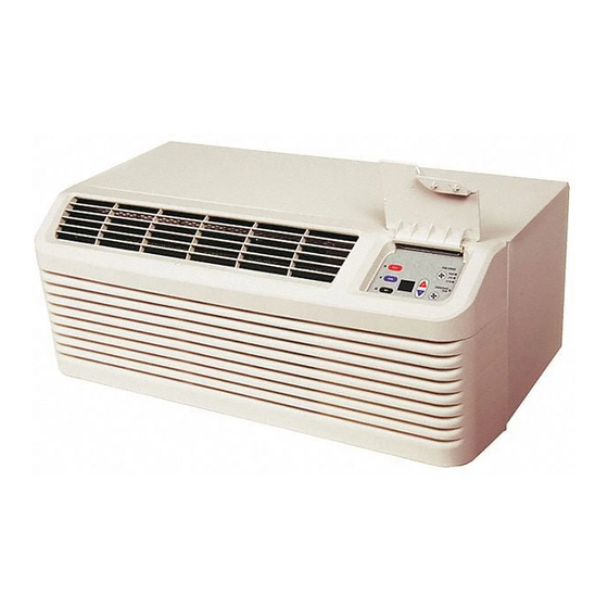
- Page 1 Maytag Corporation or its related companies and is used IO-447E under license to Goodman Company, L.P., Houston, TX, USA. All rights reserved. 10/2018 • www.amana-ptac.com 5151 San Felipe, Suite 500 Houston, TX 77056 • © 2014 - 2015, 2017 - 2018 Goodman Company, L.P.
-
Page 2: Table Of Contents
Remember, it is your responsibility to install the product safely and to know it well enough to be able to instruct a customer in its safe use. Safety is a matter of common sense...a matter of thinking be- fore acting. Most dealers have a list of specific good safety practices...follow them. - Page 3 • Automatic 3-minute compressor lockout - After the com- pressor cycles off, it will not restart for three minutes. • Automatic 2 stage electric heat - If the room tempera- ture falls to 4°F below the set point temperature, the reverse cycle heat is shut off and the electric strip heat is turned on.
- Page 4 • Energy Management System Features b. Original paid freight bill or indemnity in lieu thereof. Temperature Setback - This option can save energy dol- c. Original invoice or certified copy thereof, showing lars for unrented or unoccupied rooms by automatically trade and other discounts or reductions.
-
Page 5: Installation Instructions
Sleeve Stiffener INSTALLATION INSTRUCTIONS To ensure that the unit operates safely and efficiently, it must Wall Sleeve with Stiffener be installed, operated and maintained according to these instal- lation and operating instructions and all local codes and ordi- nances or, in their absence, with the latest edition of the Rear Closure Panel National Electric Code. - Page 6 Level Inside Outside 1/4 Bubble Wall Tilt To Sleeve Outside Outside Wall Proper Sleeve Tilt Note: For internal drain • Level from side to side. • Level from front to back. Cabinet Front Removal View 1 Level Pull the bottom of the cabinet front away from the chassis Inside Outside until the retaining clips disengage.
-
Page 7: Wiring
Front Mounting Screw Check the indoor and outdoor grilles for obstructions to air flow. The unit must be located where curtains, furniture, Lift the cabinet front off the chassis. Reverse this procedure trees, or other objects do not block the air flow to and from to reinstall the cabinet front. -
Page 8: Operating Instructions
OPERATING INSTRUCTIONS USERS CONTROLS A 7 button touch key pad, located behind the control door, controls both temperature and operation mode. The key pads Cord connection to a wall socket is not permitted for 265-volt can be used alone or in combination. units. - Page 9 section. FRONT DESK CONTROL (IN1, IN2, COM) The COM and IN2 or IN1 terminals provide control inputs for a front desk switch. Shorting across the terminals will disable unit operation. The only control function which will remain active when these terminals are shorted is freeze protection. Any switch which will produce a short circuit across these two terminals can be used as a front desk switch.
- Page 10 For DigiAIR (Fresh Air Solution) kit models, refer to IO-900*. Rotate the vent control lever to either open or close the damper. Vent Vent Open Closed Vent Door Lever Positions Hydronic Heat Installations To avoid the risk of freezing the steam or water coil during prolonged shut down periods, the vent door must be left closed No holes are permitted in chassis basepan or when the outdoor temperature might fall below freezing.
- Page 11 Location of 4 Screws • Concealed pipes and chimneys • Unheated (uncooled) areas behind the thermostat, such as an outside walls Consult the instruction sheet packaged with the thermostat for further details on mounting and operation. REMOTE THERMOSTAT OPERATION Approved thermostats vary slightly in construction and, with few exceptions, are operated similarly.
-
Page 12: Maintenance And Cleaning
Pump or thermostat options. Run 6 to 8 wires during initial installation. Tape or cap off any unused wires. NOTE: Using a thermostat with an O terminal will require that the 7 button with display control be configured (see Configura- tion Settings). - Page 13 line, etc.) or ammonia based cleaners be used to clean the Filters are removed by grasping the filter’s top and gently pulling up front or air grilles. Use care when cleaning the control area. YEARLY MAINTENANCE AND CLEANING NOTE: Use a mild biodegradable detergent such as Simple Front removal Green™...
-
Page 14: Obtaining Service
NORMAL OPERATING control panel area and fan motor with plastic. Creating this seal prevents water from entering the control area or SOUNDS AND CONDITIONS the fan motor and damaging the unit. Water trickling sounds Spray condenser coil and basepan down with water. Next Water is picked up and distributed over the coil. -
Page 15: Configuration Settings
CONFIGURATION SETTINGS The display will indicate - -. Press the key one time. 7 BUTTON TOUCH PAD WITH DISPLAY The display will then alternate between C1 and 0. The control can be configured to operate a wide range of options. The options listed below with the * are the factory To select a different configuration feature code, press the default settings. -
Page 16: Configuration Chart
CONFIGURATION SETTINGS CHART Configuration Configuration Feature Option Code Option Code Chassis Membrane * Interface Wired Thermostat Wireless Stat & 7-Button Locked Membrane do not use ID Fan Operation do not use Button present Revert to Cyclic Always run fan (even if Off) do not use Revert to Continuous PTC (Standard Cooler) - Page 17 Configuration Configuration Feature Option Code Option Code Smart Vent Operation On only when ID fan runs On when ID fan runs & room occupied Runs continuously On when room is occupied Economizer Economizer with compressor assist Vent Dehumid Make-up Air Kit Operation May be on anytime Allowed on except in Off mode...
-
Page 18: Diagnostic Maintenance & Status Report
DIAGNOSTIC MAINTENANCE OPERATING TEMPERATURES. • If not in Diagnostic Status Report Mode, enter as instructed & STATUS REPORT above and press the Fan Speed key. The Diagnostic Maintenance & Status Report provides detailed • If already in Diagnostic Status Report mode, press the information on PTAC control operation and operational status Fan Speed key. -
Page 19: Diagnostic Codes
DIAGNOSTIC CODES ERROR CODE STATUS DISPLAY SUGGESTED ACTION LIGHT Freeze Protection Engaged. The room temperature measured No Action required. This setting will disengage when the by the wireless remote thermostat or indoor ambient room temperature rises above 43°F. thermistor active sensor falls below 40°F. Front Desk switch is closed. - Page 20 DIAGNOSTIC CODES ERROR CODE STATUS DISPLAY SUGGESTED ACTION LIGHT Indoor Ambient Thermistor reads outside the range -20°F to 200°F & the wireless thermostat is not communicating to the Replace black Indoor Ambient Thermistor or Wireless unit control or Remote Thermostat Indoor Ambient Thermistor (IAT) without a wireless remote thermostat reads outside the range -20°F to 200°F.
- Page 21 THIS PAGE INTENTIONALLY LEFT BLANK...
- Page 22 THIS PAGE INTENTIONALLY LEFT BLANK...
- Page 23 THIS PAGE INTENTIONALLY LEFT BLANK...
- Page 24 We are very interested in all product comments. Please fill out the feedback form on one of the following links: Amana® Brand Products: (http://www.amana-hac.com/about-us/contact-us). You can also scan the QR code on the right for the product brand you purchased to be directed to the feedback page.