Table of Contents
Advertisement
PRODUCT LITERATURE
1997 Lennox Industries Inc.
Dallas, Texas
Do not store or use gasoline or other
flammable vapors and liquids in the
vicinity of this or any other appliance.
Installation and service must be
performed by a qualified installer,
service agency or the gas supplier.
If the information in this manual is not
followed exactly, a fire or explosion
may result causing property damage,
personal injury or loss of life.
INSTALLATION
INSTRUCTIONS
G20R SERIES UNITS
GAS UNITS
503,560M
2/97
Supersedes 11/96
TABLE OF CONTENTS
UNIT DIMENSIONS
. . . . . . . . . . . . . . . . . . . . . . . . . . . . . . . . . . . . . . . . .
. . . . . . . . . . . . . . . . . . . . . . . . . . . . . . . . . . . .
. . . . . . . . . . . . . . . . . . . . . . . . . . . . . . . . . . . . . . . . .
. . . . . . . . . . . . . . . . . . . . . . . . . . . . . . . . . . . . . .
. . . . . . . . . . . . . . . . . . . . . . . . . . . . . . . . . . . . .
. . . . . . . . . . . . . . . . . . . . . . . . . . . . . . . . . .
. . . . . . . . . . . . . . . . . . . . . . . . . . . . . . . . . . . . . . . .
. . . . . . . . . . . . . . . . . . . . . . . . . . . . . . . . . . .
BCC TROUBLESHOOTING
RETAIN THESE INSTRUCTIONS
FOR FUTURE REFERENCE
WARNING
WHAT TO DO IF YOU SMELL GAS:
D Do not try to light any appliance.
D Extinguish any open flames.
D Do not touch any electrical switch; do not
use any phone in your building.
D Immediately call your gas supplier from a
neighbor's phone. Follow the gas supplier's
instructions.
D If you cannot reach your gas supplier, call
the fire department.
Page 1
. . . . . . . . . . . . . . . . . . . . . . . . . . . . . . . .
. . . . . . . . . . . . . . . . . . . . . . . . . . . .
. . . . . . . . . . . . . . . . . . . . . . . . . . . . . . . . . .
. . . . . . . . . . . . . . . . . . .
. . . . . . . . . . . . . . . .
. . . . . . . . . . . . . . . . . . . .
. . . . . . . . . . . . . . . . . . . .
. . . . . . . . . . . . . . . . . . . . . .
. . . . . . . . . . . . . . . . . . . . . . . .
Litho U.S.A.
2
3
4
5
. . . .
5
7
8
8
8
10
11
14
15
15
15
17
19
. . . . . .
19
20
Advertisement
Table of Contents

Related Manuals for Lennox G20R series


Summary of Contents for Lennox G20R series
-
Page 1: Table Of Contents
INSTALLATION INSTRUCTIONS PRODUCT LITERATURE 1997 Lennox Industries Inc. Dallas, Texas G20R SERIES UNITS GAS UNITS 503,560M 2/97 Supersedes 11/96 Litho U.S.A. TABLE OF CONTENTS UNIT DIMENSIONS ....... . - Page 2 G20R UNIT DIMENSIONS–INCHES (MM) 1 1/16 (27) 17 3/4 FLUE OUTLET (451) (center side to side) RETURN OPENING 1 1/16 (27) 26 1/8 (664) CONTROL VOLTAGE AIR FLOW (Left Side) LINE VOLTAGE (Both Sides) (1346) CONTROL VOLTAGE (Right Side) 2 5/8 (67) GAS PIPING INLET (Both Sides)
-
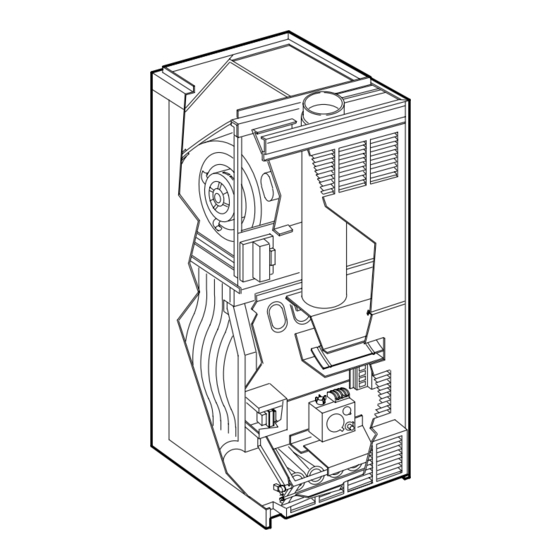
Page 3: Parts Arrangement
G20R PARTS ARRANGEMENT Page 3... -
Page 4: Requirements
NOTE-For installation on combustible floors, appliance REQUIREMENTS shall not be installed directly on carpeting, tile, or other combustible material other than wood flooring. NOTE-G20RXE series units (units equipped with flame rods) are certified for use with natural gas only. Service access Front 36 in. -
Page 5: General
NOTE G20R series units must not be used as a construction heater" at any time during any phase of construction. Very low return air tempera tures, harmful vapors and misplacement of the filters will damage the unit and its efficiency. - Page 6 CHIMNEY OR GAS VENT VENTILATION LOUVERS (Each end of attic) G20R OUTLET FURNACE WATER HEATER INLET VENTILATION LOUVERS (For unheated crawl space) NOTE-The inlet and outlet air openings shall each have a free area of at least one square inch per 4,000 Btu per hour of the total input rating of all equipment in the enclosure.
-
Page 7: Installation-Setting Equipment
3- Use duckbill pliers to bend INSTALLING unit flanges out from open BASE ANGLE ing. Install provided base bottom angle (shipped in vestibule panel) to outside of base into provided holes. See illustration at right. Se cure with screws provided. 4- Set unit over plenum. -
Page 8: Return Air Opening Guidelines
1- Refer to reverse-flow coil installation instructions for cor rectly sized opening in floor and installation of cabinet. 2- Use duckbill pliers to bend INSTALLING unit flanges out from open BASE ANGLE ing. Install provided base bottom angle (shipped in vestibule panel) to outside of base into provided holes. - Page 9 on any exhaust fans, such as range hoods and bath room exhausts, so they will operate at maximum speed. Do not operate a summer exhaust fan. Close fireplace dampers. 4- Follow the lighting instructions. Place the appliance being inspected in operation. Adjust thermostat so appliance will operate continuously.
-
Page 10: Gas Piping
unit. Tap must be accessible for test gauge connection. GAS PIPING See figure 12. NOTE-In case emergency shutoff is required, shut off 1- This unit is shipped standard for left side installation of main manual gas valve and disconnect main power to gas piping. - Page 11 NOTE-Capacity given in cubic feet of gas per hour (kilo liters of gas per hour) and based on 0.60 specific gravity gas. Page 11...
-
Page 12: Electrical
The furnace must be isolated from the gas supply sys from Lennox. The kit allows the furnace blower to run tem by closing its individual manual shut-off valve dur continuously on low speed. - Page 13 Left side thermostat wire entry. Right side thermostat wire entry. Page 13...
- Page 14 Page 14...
-
Page 15: Unit Start-Up
UNIT START–UP 4- This appliance is equipped with an ignition device which automatically lights the pilot. Do try to light the pilot by hand. 5- Remove lower access panel. 6- On Honeywell VR8204 gas valves, turn knob on gas valve clockwise . -
Page 16: High Altitude Information
11-Set thermostat to desired setting. NOTE-When unit is initially started, steps 1 through 11 See figures 22 and 21 for gas may need to be repeated to purge air from pilot line. pressure adjustment screw location. 12-If the appliance still will not operate, follow the instruc tions To Turn Off Gas To Unit"... - Page 17 6- Pull harness connector and wires through blower ac cess panel opening. 7- Select desired taps for heating and cooling. (White = common, Red = heating, Black = cooling) 8- Depress harness connector tab to release wire termi nal. Select connector location for new speed (refer to unit wiring diagram).
-
Page 18: Service
When dry, filters should be sprayed with filter handi coater before replacing. Filter Handicoater is RP prod ucts coating no. 418 and is available as Lennox part no. P-8-5069. 8- Right filter should be under tab of right filter support angle. - Page 19 3- Disconnect supply gas piping. 4- Remove screws holding burner box damper in place and remove burner box damper assembly and damp er prove switch cover. 5- Remove screws securing removable burner box top. 6- Remove screws holding gas manifold in place and pull burners from heat exchanger.
-
Page 20: Repair Parts
Draft hood REPAIR PARTS LIST Main burners Main burner orifices Pilot burner Gas manifold Gas valve Flame sensor Upper access panel Ignition control Lower access panel Ignition cable Top strip Igniter Control box cover Vent pipe extension Pilot Mounting bracket Pilot orifice Transformer Main burner with pilot mount... - Page 21 START DOES UNIT OPERATE? CHECK FUSE. REPLACE IF NEEDED. CHECK: 1-UNIT POWER 24VAC ACROSS 2-INTERLOCK SWITCH R & C? 3-TRANSFORMER 4-LIMIT SWITCH JUMPER ACROSS SCREWS R & G BLOWER REPLACE REPLACE 120VAC ACROSS 120VAC ACROSS RUNNING ON HIGH N & ACC? N &...