Table of Contents
Advertisement
Quick Links
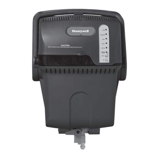
Steam Humidifier
INCLUDED IN THIS HUMIDIFIER BOX
Tools needed to install Steam Humidifier
Wire cutter/stripper
1-3/4-in. diameter hole saw
1/8-in. drill bit
Standard screwdriver
18-gauge wire (up to 5 conductor)
Torx driver T-20 and T-30
Other Requirements
Steam Humidifier flushes water at or above 140°F (60°C).
Refer to local codes for proper draining practices
for hot water.
Condensate pump rating of 212°F (100°C) if used.
Drip pan with water sensor shut-off required underneath
Steam Humidifier if installed in or above finished space.
Remote installation requires separate purchase of the
Honeywell Remote Mounting Kit (#50024917)
G
F
J
K
3
PROFESSIONAL INSTALLATION GUIDE
H
L
Steam Humidifier
Mounting bracket and hardware
Backflow preventer
Saddle valve
Water supply hose
E
Drain hose (10 feet)
F
Duct nozzle and gasket
G
Owner's manual
H
Service label
I
HumidiPRO Digital Control
J
3
Hose clamp
K
Water Hardness Test Kit
L
RO Filter System
M
*RO Tank not needed with installation
TM
E
I
M*
69-2285-09
Advertisement
Table of Contents
Troubleshooting

Related Manuals for Honeywell Steam Humidifier


Summary of Contents for Honeywell Steam Humidifier
- Page 1 Drain hose (10 feet) Torx driver T-20 and T-30 Duct nozzle and gasket Other Requirements Owner’s manual Steam Humidifier flushes water at or above 140°F (60°C). Service label Refer to local codes for proper draining practices HumidiPRO Digital Control for hot water.
-
Page 3: Table Of Contents
NEED HELP? For assistance with this product please visit http://yourhome.honeywell.com or call Honeywell Customer Care toll-free at 1-800-468-1502. Read and save these instructions. ® U.S. Registered Trademark. Patents pending. Copyright © 2014 Honeywell International Inc. All rights reserved. Steam Humidifier System 69-2285—09... -
Page 4: Critical Installation Information
Choosing the Filter If the water tests in range 2 then the steam humidifier will require the use of a whole-house water softener for optimal performance. Failure to use softened water in this situation can potentially lead to drastically increased maintenance requirements and premature failure of the steam humidifier and its components. -
Page 5: Set The Automatic Flush Cycle Timing
If water hardness is in range 1: M29661 Honeywell recommends using the RO Filtration system Proceed to “Water Supply and Drain Connections” on page 14. See “Reverse Osmosis Filter” on page 24 to install the filter. For hard water without For water that is filtered through... - Page 6 In applications with a water softener, it is critical for the steam humidifier to draw its water supply from the cold water line after the water softener.
-
Page 7: Proper Sizing Of A Steam Humidifier Humidifier
It is vital to take all of these factors into account when sizing a steam humidifier for a particular home. Undersizing the humidifier will not only reduce the potential to meet the a desired humidity set point, it may also lead to extensive system fan run time or higher operating costs as the system tries to deliver to the control’s setting. - Page 8 Converting square footage to cubic volume requires multiplying the square footage by the ceiling height (i.e. 2000 square foot space with 10 foot ceilings is 20,000 cubic feet). In general, the higher the ceilings, the smaller the square footage space each Steam Humidifier will cover since it must humidify the additional air volume.
-
Page 9: Steam Humidifier Pre-Install Information
Complete this information sheet and leave on all jobsites PRACTICE In the event that a service technician needs to call in to the steam humidifier support techline, the following information is typically required for the Honeywell tech support specialist to accurately evaluate each situation. -
Page 10: Safety Definitions And Precautions
WARNING: Indicates a hazardous situation which, if not avoided, could result in death or serious injury. Safety Precautions Make sure you read and understand the following safety hazards before installing, using, or working with the steam humidifier: • Do not direct the steam nozzle at people. -
Page 11: Setting Homeowner Expectations
Setting Homeowner Expectations Make sure the homeowners know what to expect from their steam humidifier. Discuss the following points with the homeowners and answer any questions they have. • Achieving Humidity Setpoint. It may take up to a week of continuous operation to achieve the humidity setpoint. -
Page 12: Important Installation Requirements
See “Appendix C: Parts List” on page 55. • If used near a pool or spa, make sure steam humidifier can not fall into the water or be splashed. Also, ensure steam humidifier is plugged into a ground fault interrupted (GFI) outlet. -
Page 13: Choosing A Mounting Method
Choosing a Mounting Method Before installing steam humidifier in a home, you must decide which mounting method you want to use: Which is right for you? DUCT MOUNTING – if you can mount steam REMOTE MOUNTING – if a suitable... -
Page 14: Duct Mounting
I have confirmed local codes for proper draining practices for hot water I have chosen an installation location that meets the requirements on page 10 Follow these steps to mount steam humidifier directly to the supply duct of the homeowner’s HVAC equipment. STEP ONE:... -
Page 15: Step Three: Install Mounting Bracket To The Duct
Lift steam humidifier into place against the mounting bracket. Insert the nozzle directly into the duct hole. Check the foam gasket – it must form a tight seal in the duct hole. Push down to secure steam humidifier to the bracket arms. M29601A Before proceeding to Plumbing:... -
Page 16: Water Supply And Drain Connections
Cut the water line so it is long enough to reach from the water filter to the supply fitting on the bottom of the steam humidifier. Insert the water line into the steam humidifier supply fitting. Note: Failure to check for a tight fit with plastic water line MCR35266 could result in the line coming loose in the future. -
Page 17: Step Three: Connect Steam Humidifier To The Cold Water Pipe
STEP THREE: Connect Steam Humidifier to the Cold Water Pipe Connect one end of the remaining length of water line to the backflow preventer. Apply a modest pull to ensure a tight fit. See “Reverse Osmosis Filter” on page 24 if using the Reverse Osmosis Filter. -
Page 18: Other Plumbing Options
• Pump must be powered when Steam Humidifier is operating. • Use a pump with a built-in overflow sensor or install the pump in a drip pan with wet switch wired to turn off Steam Humidifier. Steam Humidifier System 69-2285—09... - Page 19 SIZE TO FIT PUMP OUTPUT SINK 1-1/2 IN. MINIMUM PVC ALTERNATIVE STAINLESS STEEL THIS CONFIGURATION ALLOWS FOR SLOTTED BAND REMOVAL OF THE TRAP COUPLING SIZED TO FIT PIPE (COPPER, WELD PVC, CPVC) M28681 1-1/2 IN. PVC Steam Humidifier System 69-2285—09...
- Page 20 3/4 IN. FNPT X 1-1/2 IN. PVC SIZE TO FIT PUMP OUTPUT STAINLESS STEEL ALTERNATIVE SLOTTED BAND THIS CONFIGURATION ALLOWS FOR COUPLING SIZED TO REMOVAL OF THE TRAP FIT PIPE (COPPER, 1-1/2 IN. PVC M28680 PVC, CPVC) Steam Humidifier System 69-2285—09...
-
Page 21: Remote Installation
Remote Installation Use remote installation when no suitable duct mounting location can be found on the homeowner’s HVAC system. For detailed instructions on remote installation, see the steam humidifier Remote Mount Kit Installation Instructions (69-2317). Always pitch the remote Adapter Nozzle upwards... - Page 22 Minimum 2 inches Water in elbow. Always consult and follow local plumbing codes for drain pipe Note: Some building codes require size and maximum temperature requirement. an air gap between discharge hose and floor drain. M29636 Steam Humidifier System 69-2285—09...
-
Page 23: Proper Hose Installation
Proper Hose Installation Furnace or Mechanical Room Remote Note: If air handler location temperatures will drop below freezing at any time, Steam Humidifier must be mounted in a conditioned space, running a remote hose to the duct. Duct Mount Remote... - Page 24 • Height of P-traps must be greater than the duct static pressure. (Typical 3 in. will suffice.) • Minimize sharp bends and elbows. • Insulating the remote hose in unconditioned spaces will sustain efficiency better than not insulating the hose. Steam Humidifier System 69-2285—09...
- Page 25 Sharp hose bends. Does not have at least 6 in. vertical rise immediately out of humidifier, and nozzle is not pitched up. Horizontal run does not have minimum pitch of 2 in. per ft. Sharp hose bends. Downward pitch does not have trap at its lowest point. Steam Humidifier System 69-2285—09...
-
Page 26: Reverse Osmosis Filter
Reverse Osmosis Filter If the steam humidifier owner’s home has water tested in range 1 on the water test strip, the Honeywell Reverse Osmosis (RO) Filtration System (HM600XROF1) should be installed in the water supply line. Failure to use the RO kit in these situations will lead to increased maintenance requirements and possible failure of the steam humidifier and its components. -
Page 27: Setting Up The Ro Filter
See the instruction sheet packaged with the RO Filtration System for complete installation instructions. 1. Mount the base chassis to a surface capable of holding up to 7 pounds between the home’s cold water line and the steam humidifier location. (Mounting hardware is provided.) t e r 2. -
Page 28: Maintaining The Ro Filter
Maintaining the RO Filter Honeywell recommends the following maintenance steps be performed at least once each humidification season. Remove filters #1, #2, and #3, in this order. Reconnect filters in this order: • Empty water from the #3 filter and reconnect to the RO System. -
Page 29: Before Wiring Steam Humifier
I will read the section “Deciding on the Wiring Configuration” beginning on page 29 Using the DIP Switches The wiring features are configured by DIP settings, which are described under the steam humidifier cover. STEP ONE: Remove the Steam Humidifier Cover CAUTION: Voltage Hazard. - Page 30 If DOWN (default), steam humidifier looks for R input before allowing humidity. • If UP, steam humidifier does not look for R Input before allowing humidity. Power is still allowed to pass through if R is wired. See “Make Power M29611 Monitoring Decision”...
-
Page 31: Deciding On The Wiring Configuration
You need to decide on the configurations you will use before wiring the steam humidifier, These decisions will affect how the connections are made, how the DIP switches are set, and how steam humidifier operates for the homeowner. - Page 32 IMPORTANT NOTE: The images below are not complete wiring diagrams. It only depicts power monitoring and is not meant to be a stand alone diagram. Please refer to the “Wiring the steam humidifier” section in the following pages for complete wiring diagrams.
-
Page 33: Step Two: Make System Fan Regulation Decision
Make System Fan Regulation Decision System Fan Regulation is a configuration that requires steam humidifier to monitor the HVAC system fan and make sure the fan is on if humidity is needed. This helps ensure that airflow will distribute humidity into the living space, and prevents water condensation in the duct. - Page 34 IMPORTANT NOTE: The images below are not complete wiring diagrams. It only depicts power monitoring and is not meant to be a stand alone diagram. Please refer to the “Wiring the steam humidifier” section in the following pages for complete wiring diagrams.
-
Page 35: Step Three: Make Add-On Air Proving Decision
IMPORTANT NOTE: The image below is not a complete wiring diagram. It only depicts power monitoring and is not meant to be a stand alone diagram. Please refer to the “Wiring the steam humidifier” section in the following pages for complete wiring diagrams. -
Page 36: Using The Terminals
Wiring the Steam Humidifier You will need to wire steam humidifier using the diagram that applies to your humidity control. Remember to include the wiring and DIP settings required for power monitoring, system fan regulation, and add-on air proving (if used). -
Page 37: Using The Correct Control Diagram
Before wiring to HVAC terminals, disconnect HVAC equipment power. Make sure steam humidifier is not plugged in. Follow the diagram for control options 1 through 14 to wire the steam humidifier. Refer to the installation manual provided with the control for additional instructions if needed. -
Page 38: Installing The Humidistat
Hold the wallplate up to the desired location on Find your mark and drill a 1/2 in. hole in the duct and make a mark inside the duct tube the duct. This is where the duct tube will be hole. inserted to capture air. Steam Humidifier System 69-2285—09... -
Page 39: Wiring The Humidistat
S OUTDOOR SENSOR OUTDOOR S OUTDOOR SENSOR sensor. TEMPERATURE SENSOR NOTES: C AND R MUST BE CONSTANT 24VAC! RECOMMENDED TO WIRE TO FURNACE/AIR HANDLER CONTROL BOARD. DO NOT WIRE C AND R TO HUMIDIFIER TRANSFORMER! M34865 Steam Humidifier System 69-2285—09... -
Page 40: Mounting The Outdoor Sensor
1. Remove the sensor from the mounting clip. 2. Mark the area on the location selected for mounting the sensor mounting clip. 3. Mount the clip. Image on right shows typical locations for out- door sensor. M7514A Steam Humidifier System 69-2285—09... - Page 41 Pigtail wiring can be used. 2. Mount C7089 in its mounting clip. USE APPROPRIATE MOUNTING MEANS FOR THE TYPE OF STRUCTURE. 3. Plug wiring hole using nonhardening caulk or putty. PLUG WIRING HOLE WITH NON-HARDENING CAULK OR PUTTY. M34611 Steam Humidifier System 69-2285—09...
- Page 42 (RH% Setting Only). Advanced Installer Setup See next page to customize feature operation. Installer System Test If Advanced Installer Setup is not required, skip to “Installer System Test/Checkout” on page 42. Steam Humidifier System 69-2285—09...
- Page 43 Advanced Installer Setup Honeywell has already programmed this control to work properly in most applications. However, you can adjust the advanced settings by following the steps below. To begin, press and hold the p and LIGHT buttons until Press p or q to change settings.
- Page 44 H6062 Specifications Humidity Ranges: Operating Ambient Temperature Humidify: • 32° to 120°F (0° to 48.9°C) • Default: 10% to 60% Operating Relative Humidity • Total Range Available: 10% to 90% • 5% to 90% (non-condensing) Steam Humidifier System 69-2285—09...
-
Page 45: Startup And Checkout
Startup and Checkout When installation is complete, plug steam humidifier in and turn the humidity control on. Make sure it is running properly before turning the system over to the homeowner. Once steam humidifier is running, day-to-day operation is hands-free, except for occasional cleaning. The homeowner can use the control to adjust the humidity setpoint, adjust the frost setting (if used), or turn steam humidifier off as desired. -
Page 46: Routine Maintenance
• Cold water will enter the tank to lower water temperature below 140°F (60°C) before draining. • At the end of the cycle, steam humidifier refills the tank with fresh water and automatically returns to normal operation. Manual Cleaning Cycle Honeywell recommends that steam humidifier be manually cleaned and the water filter be changed at least once each humidification season. - Page 47 When the Empty light is on, the tank is empty. The tank may now be removed for cleaning or other service. Be sure to disconnect the steam humidifier from power before beginning the cleaning procedure M29629A Steam Humidifier System 69-2285—09...
-
Page 48: Step Two: Remove The Water Tank
CAUTION: Scalding hazard. Do not attempt to remove steam humidifier from the mounting bracket during operation or when the tank is full of water. The heating element could be hot when tank is removed. Failure to comply could result in severe scalding. -
Page 49: Step Three: Clean The Tank
STEP FOUR: Replace the Water Level Sensor (if necessary) WARNING: Electrocution Hazard. Steam Humidifier must be unplugged before removing the cover. Hazardous voltage could cause death or serious injury. Remove Steam Humidifier cover and inspect water level sensor. If debris buildup is present, clean with recommended cleaning agent. -
Page 50: Water Level Sensor Troubleshooting Steps
Place the OHM METER PROBES on top of sensor probes. • Measure the resistance between the following locations: Between P1 and P3 Between P1 and P4 Between P2 and P4 Between P4 and P5 WATER LEVEL SENSOR M32994 Steam Humidifier System 69-2285—09... -
Page 51: Step Five: Reinstall The Tank
Attach tank by securing the latch and plug in steam humidifier. If the control is calling for humidity, the humidifying light will blink at startup. Steam humidifier waits 5 minutes to complete the tank reconnection before acting on this call. -
Page 52: Troubleshooting
Steam Humidifier will attempt to recover up to five times in a 24-hour period. • If Steam Humidifier is unable to recover by itself within 24 hours, the red Service light blinks in a series that indicates the fault detected. - Page 53 Yes, system will 1. Verify the electrical circuit is not overloaded. insufficient. return to “Ready” 2. Unplug and replug steam humidifier in to see if the fault if fault no longer returns. exists in one hour. 3. If the fault returns, unplug steam humidifier and remove cover.
- Page 54 (Performed Only By Professional HVAC Technician) Blinks HVAC power Yes, system will 1. Unplug and replug steam humidifier in to see if power returns. not present. return to “Ready” 2. If power does not return, ensure HVAC equipment has power.
- Page 55 5. Press and hold the Go button to clear the fault. 6. If the fault persists, replace the air proving device being used. Power to the wireless Yes, system will 1. Verify wiring between steam humidifier and the wireless adapter overloaded. return to “Ready” adapter.
-
Page 56: A: Specifications
HM609: 8,000–18,400 cubic feet • HM609: 10A, 120VAC HM612: 12,000–24,000 cubic feet • HM612: 12A, 120VAC Note: Higher volumes require more steam humidifier run • 15A, 120VAC interlock switch time. • Thermostat/HVAC power monitor (R to C): 10mA resistive at 24VAC Weight •... -
Page 57: B: Advanced Steam Humififier Wiring
Before wiring to HVAC terminals, disconnect HVAC equipment power. Make sure Steam Humidifier is not plugged in. Follow the diagram for control options 1 through 14 to wire the Steam Humidifier. Refer to the installation manual provided with the control for additional instructions if needed. - Page 58 B: Advanced Steam Humidifier Wiring OPTION 3: VisionPRO IAQ Wiring with Fan Delay • Follow this diagram if you are using VisionPRO IAQ with Steam Humidifier’s fan-delay feature. • The system fan will turn on when the water temperature reaches 176°F (80°C).
- Page 59 B: Advanced Steam Humidifier Wiring OPTION 5: Prestige IAQ with fan delay • Follow this diagram if you are using Prestige IAQ with Steam Humidifier’s fan-delay feature. • The system fan will turn on when the water temperature reaches 176°F (80°C).
- Page 60 OPTION 6: Prestige IAQ or All New VisionPRO without fan delay • Follow this diagram if you are using Prestige IAQ to turn system fan on immediately with humidity call. THX9421R FURNACE STEAM HUMIDIFIER THM5421R PRESTIGE IAQ AND STEAM HUMIDIFIER WITHOUT FAN DELAY M32919B Steam Humidifier System 69-2285—09...
- Page 61 W1/E Humidistat Equipment Furnace DS/BK HZ432 (AFS Monitor Recommended) Steam Humidifier Alternative (Power Monitor Setting) M32920A OPTION 8: Wiring Prestige or All New VisionPRO with wireless Steam Humidifier THM4000R1000 THX9321R SUBBASE FURNACE WIRELESS SETTINGS PRESTIGE WITH WIRELESS STEAM HUMIDIFIER WIRELESS...
- Page 62 B: Advanced Steam Humidifier Wiring OPTION 9: Prestige IAQ or All New VisionPRO controlling Steam Humidifier with zoning with fan delay (recommended) THX9421R HZ432 FURNACE STEAM THM5421R HUMIDIFIER AFS MONITOR RECOMMENDED M33055B Steam Humidifier System 69-2285—09...
- Page 63 B: Advanced Steam Humidifier Wiring OPTION 10: Steam Humidifier wired to a dedicated fan/blower STEAM HUMIDIFIER TrueIAQ TRANSFORMER R8222 (120 VOLT HOT) (120 VOLT COMMON) M33056 (AFS Monitor Recommended) Alternative (Power Monitor Setting) M32922A ISU 25 must be set to 3...
- Page 64 B: Advanced Steam Humidifier Wiring OPTION 11: Prestige IAQ or All New VisionPRO controlling Redlink wireless Steam Humidifier with zoning NOTE: To get air humidity to all zones in idle mode you would need to jump the G on all zones being used and verify that the thermostat does not have a Y/G interconnect.
- Page 65 A DOUBLE-POLE RELAY SUCH AS THE R8228D1018 IS REQUIRED. AN AIR-FLOW SWITCH IS RECOMMENDED. IF AN AIR FLOW SWITCH IS NOT USED THERE DOES NOT NEED TO BE A WIRE ATTACHED TO C ON THE STEAM HUMIDIFIER AND THE #4 DIP SWITCH NEEDS TO BE SET TO “ON”.
- Page 66 AN AIR-FLOW SWITCH IS RECOMMENDED. IF AN AIR FLOW SWITCH IS NOT USED THERE DOES NOT NEED TO BE A WIRE ATTACHED TO C ON THE STEAM HUMIDIFIER AND THE #4 DIPSWITCH NEEDS TO BE SET TO “ON”. GT IS NOT REQUIRED FOR THIS APPLICATION. SINCE THE PRESTIGE IAQ THERMOSTAT DOES NOT HAVE A Y/G INTERCONNECT, PARALLEL WIRING CAN BE DONE (AS SHOWN).
- Page 67 Y/Y2 FURNACE TERMINALS NOTES: YOU MUST ADD A 24VAC ISOLATION RELAY BETWEEN THE STEAM HUMIDIFIER AND THE AIR HANDLER. AN R8222B1067 COULD BE USED. THE 50027910-001 AIR-FLOW SWITCH (AFS) IS RECOMMENDED TO ENSURE THERE IS AIR-FLOW WHEN THE HUMIDIFIER IS RUNNING. IF THE AFS IS NOT USED, THE 4 DIPSWITCH MUST BE SET TO THE ON POSITION AT THE HUMIDIFIER (UP).
-
Page 68: C: Parts List
Qty. 1 Tank Sediment screen 50024921-003 Qty. 1 Steam humidifier handle 50032048-002 Qty. 25 Resident Humidifier quick connect adapter 50043771-001 Qty. 25 Steam humidifier filter for Solenoid Valve 32001647-001 Qty. 25 Residential Humidifier cone screen filter 50044721-001 Qty. 12 water hardness test kit... - Page 72 Automation and Control Solutions Honeywell International Inc. 1985 Douglas Drive North Golden Valley, MN 55422 http://customer.honeywell.com ® U.S. Registered Trademark. © 2014 Honeywell International Inc. 69-2285—09 M.S. Rev. 08-14 Printed in U.S.A.