Sony RDR-GX350 Service Manual
Hide thumbs
Also See for RDR-GX350:
- Operating instructions manual (112 pages) ,
- Service manual (157 pages) ,
- Service manual (141 pages)
Table of Contents
Advertisement
Quick Links
Download this manual
See also:
Service Manual
SERVICE MANUAL
System
Laser: Semiconductor laser
Channel coverage (Except AUS,SP):
NTSC (national television system
committee)/PAL-M (Phase alternation
line-system M)/PAL-N (Phase
alternation line-system N)
VHF (very high frequency): 2 to 13
UHF (ultra high frequency): 14 to 69
CATV (cable television): A8 to A1,
A to W, W+1 to W+84
Channel coverage (AUS,SP):
Oceanian Model:
PAL/SECAM (B/G, D/K, I, L)
Except Oceanian models:
PAL/SECAM (B/G, D/K, I)/NTSC
VHF: E2 to E12, R1 to R12, Italian A
to H, Ireland A to J, South Africa 4
to 11, 13, AS0 to AS12, NZ1 to NZ11
UHF: E21 to E69, R21 to R69, B21 to
B69, AS28 to AS69
CATV: S01 to S05, S1 to S20
HYPER S21 to S41
The above channel coverage merely ensures
the channel reception within these ranges. It
does not guarantee the ability to receive
signals in all circumstances. For details, see
"Receivable channels" (page 100).
Video reception:
Frequency synthesizer system
Audio reception: Split carrier system
Aerial out:
75-ohm asymmetrical aerial socket
Timer: Clock: Quartz locked/Timer
24-hour cycle (digital)
Except (E,CND)/
12-hour cycle (digital) (E,CND)
Power back-up duration: 1 hour
Video recording format:
MPEG-2, MPEG-1
Audio recording format/applicable bit rate:
Dolby Digital 2 ch 256 kbps/128 kbps
(in EP, SLP, and SEP mode), PCM
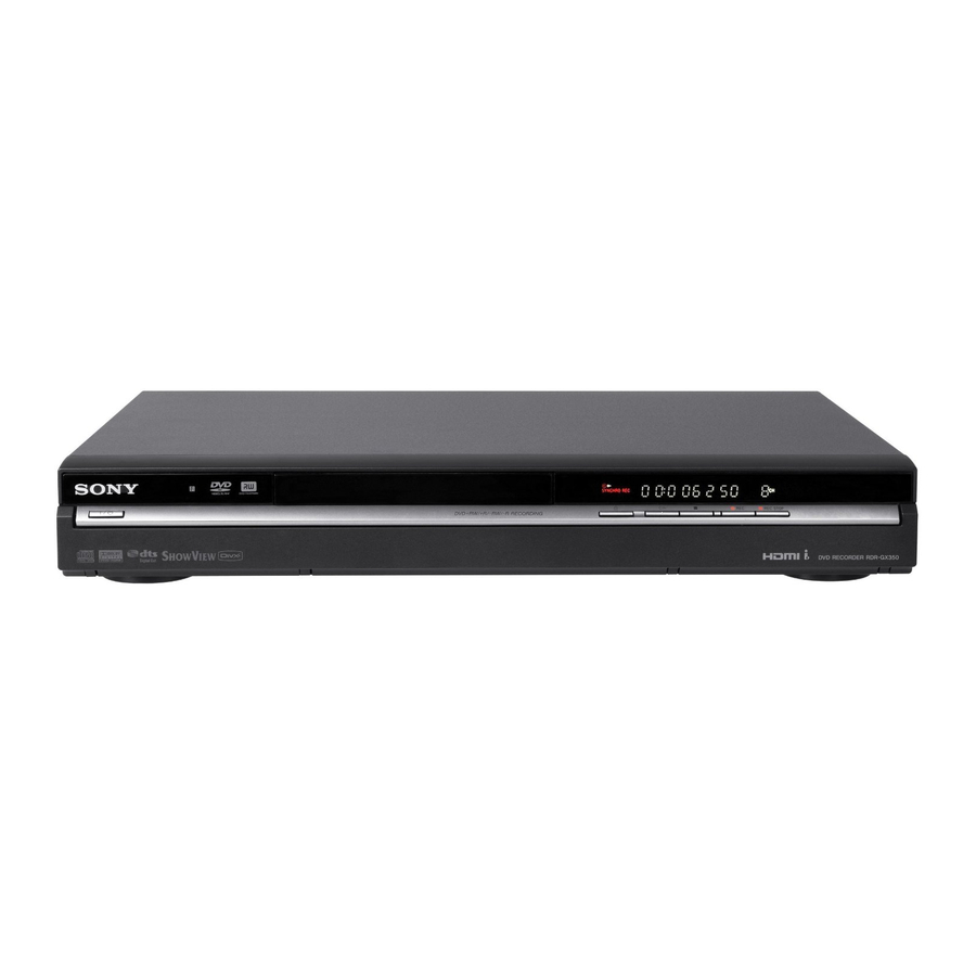
RDR-GX350/HX750/HX950
Photo : RDR-HX750
RMT-D246P
SPECIFICATIONS
Inputs and outputs
LINE OUT
(AUDIO): Phono jack/2 Vrms/10 kilohms
(VIDEO): Phono jack/1.0 Vp-p
(S VIDEO): 4-pin mini DIN/Y: 1.0 Vp-p,
C: 0.3 Vp-p (PAL) (AUS, SP ONLY)
C: 0.286 Vp-p (NTSC)
LINE 1/LINE 2/LINE 3*
* LINE 3 ONLY for these destinations:
(GX350: CND/HX750: TW, CND, E)
(AUDIO): Phono jack/2 Vrms/more than
22 kilohms
(VIDEO): Phono jack/1.0 Vp-p
(S VIDEO): 4-pin mini DIN/Y: 1.0 Vp-p,
C: 0.3 Vp-p (PAL) (AUS, SP ONLY)
C: 0.286 Vp-p (NTSC)
DV IN: 4-pin/i.LINK S100
DIGITAL OUT (COAXIAL): Phono jack/
0.5 Vp-p/75 ohms
COMPONENT VIDEO OUT
(Y, P
/C
, P
/C
) (Except CND):
B
B
R
R
Phono jack/Y: 1.0 Vp-p,
P
/C
: 0.7 Vp-p, P
/C
: 0.7 Vp-p
B
B
R
R
(Y, P
, P
) (CND ONLY):
B
R
Phono jack/Y: 1.0 Vp-p,
P
: 0.7 Vp-p, P
: 0.7 Vp-p
B
R
HDMI OUT: HDMI 19-pin-Standard
Connector
USB:
RDR-HX750/HX950:
USB jack Type A (For connecting
digital still camera, Memory card
reader and USB memory)
USB jack Type B (For connecting
PictBridge-compatible printers)
RMT-D245A/D245P/D246A/D246P
General
Power requirements:
220 – 240 V AC, 50/60 Hz
(AUS, SP ONLY)
110 – 240 V AC, 50/60 Hz
(E, BR, AR ONLY)
120 V AC, 60 Hz (CND ONLY)
110 V AC, 60 Hz (TW ONLY)
Power consumption:
RDR-GX350: 22W
RDR-HX750/HX950: 42W
Dimensions (approx.):
430 × 66.5 × 286 mm
(width/height/depth) incl. projecting parts
Hard disk drive capacity:
RDR-HX750: 160 GB
RDR-HX950: 250 GB
Mass (approx.):
4.4 kg (HX750/HX950)
3.6 kg (GX350)
Operating temperature: 5°C to 35°C
Operating humidity: 25% to 80%
Supplied accessories
Power cord/(Mains lead) (1)
Antenna cable/Aerial cable (1)
Audio/Video cord (1)
Remote commander (remote) (1)
RDR-HX750/HX950:
Set top box controller (1)
Size AA (R6) batteries (2)
Plug adaptor (E ONLY)
Specifications and design are subject to
change without notice.
DVD RECORDER
Australia New
Zealand Model
RDR-GX350/HX750/HX950
Argentina Model
RDR-GX350
Brazilian Model
RDR-GX350
Canadian Model
RDR-GX350/HX750
E Model
RDR-GX350/HX750
Singapore Model
RDR-GX350/HX750/HX950
Taiwan Model
RDR-HX750
Advertisement
Table of Contents

Related Manuals for Sony RDR-GX350


Summary of Contents for Sony RDR-GX350
-
Page 1: Dvd Recorder
UHF (ultra high frequency): 14 to 69 * LINE 3 ONLY for these destinations: Power consumption: CATV (cable television): A8 to A1, (GX350: CND/HX750: TW, CND, E) RDR-GX350: 22W A to W, W+1 to W+84 (AUDIO): Phono jack/2 Vrms/more than RDR-HX750/HX950: 42W Channel coverage (AUS,SP): 22 kilohms Dimensions (approx.):... - Page 2 THESE COMPONENTS WITH SONY PARTS WHOSE PART CRITIQUES POUR LA SÉCURITÉ DE FONCTIONNEMENT. NE NUMBERS APPEAR AS SHOWN IN THIS MANUAL OR IN REMPLACER CES COMPOSANTS QUE PAR DES PIÈSES SONY SUPPLEMENTS PUBLISHED BY SONY. DONT LES NUMÉROS SONT DONNÉS DANS CE MANUEL OU DANS LES SUPPÉMENTS PUBLIÉS PAR SONY.
-
Page 3: Table Of Contents
RDR-GX350/HX750/HX950 TABLE OF CONTENTS SERVICE NOTE DV Camcorder Dubbing ............1-17 Before DV Camcorder Dubbing ........1-17 Dubbing an Entire DV Format Tape Disc Removal Procedure in the Tray cannot be Ejected (DV One Touch Dubbing) ..........1-18 (Forced Ejection) ..............5 Dubbing Selected Scenes (Manual Dubbing) .... - Page 4 RDR-GX350/HX750/HX950 PRINTED WIRING BOARDS AND SERVICE MODE SCHEMATIC DIAGRAMS 6-1. SERVICE MODE MAP ............6-2 6-2. Diagnostic Mode ..............6-3 4-1. Frame Schematic Diagram ..........4-1 6-2-1. Model Setting ............6-3 4-2. Printed Wiring Boards and Schematic Diagrams ....4-3 6-2-2.
-
Page 5: Service Note
RDR-GX350/HX750/HX950 SERVICE NOTE 1. DISC REMOVAL PROCEDURE IN THE TRAY CANNOT BE EJECTED (FORCED EJECTION) 1. Remove the upper case. 2. Insert the stiff wire in the hole and eject the tray. Hole 1 The stiff wire Open the tray NOTES DURING THE FORCED EJECTION 1. -
Page 6: Model Name Setting Method When Engine Is Replaced
RDR-GX350/HX750/HX950 3. MODEL NAME SETTING METHOD WHEN ENGINE IS REPLACED Required equipment: • Remote controller (RMT-D245A/D245P/D246A/D246P) • Service remote controller (J-6090-203-A) • Monitor Model name delete method 1. Turn the main POWER ON. 2. Press the following buttons on the service remote controller in this order.: “ESC”... -
Page 7: How To Diagnose Hdd Failure
Failure to physically Replace the SATA cable or Please consult your identify the HDD (no Blank space power cable. nearest Sony dealer. connection, defective Replace the HDD. Note that contents on HDD, interface error). Replace the FE or part in the the HDD may be SATA/ATA communication. -
Page 8: Display [E01] On Fld With Unrecognized Hdd
RDR-GX350/HX750/HX950 4-3. Display [E01] on FLD with unrecognized HDD Is the HDD free from irregular noises? Is “#” displayed? Unauthorized HDD Replace the HDD * For information about replacing the HDD, see Section 2, page 2-5. After replacing the HDD, perform “Factory Check”... -
Page 9: Display [E02] On Fld
RDR-GX350/HX750/HX950 4-4. Display [E02] on FLD Is the HDD free from Replace the HDD irregular noises? Note: When performing Factory Check, the data saved to the HDD Factory check by the customer is erased. Obtain customer consent before performing Factory Check. -
Page 10: Factory Check
RDR-GX350/HX750/HX950 4-6. Factory Check Pull out and then reconnect the AC cable. Press the “ESC” key followed by the “P.RUN” key to start Formatting. When “B COMPLETE” appears, the Factory Check is complete. Press the “Power” button. The unit starts normally. -
Page 11: Performance Check
RDR-GX350/HX750/HX950 4-8. Performance Check Press the “ESC” key, then the “A.MON” key. This is a reading test across all sectors of the HDD. Data recorded on the HDD will not be erased, because no writing operation is performed. Time required for testing: Approx. 45 min/160 G... -
Page 12: General
VCR or amplifier (receiver). Sony is not liable and will not enclosure. outlet, even if the recorder • Do not use the recorder in a compensate for any lost itself has been turned off. -
Page 13: Hookups And Settings
RDR-GX350/HX750/HX950 Usable disc versions (as of April 2007) Playable discs • 8x-speed or slower DVD+RWs • 6x-speed or slower DVD-RWs (Ver.1.1, Ver.1.2 with CPRM Icon used in • 16x-speed or slower DVD+Rs Type Disc Logo Characteristics this manual • 16x-speed or slower DVD-Rs (Ver.2.0, Ver.2.1 with CPRM... -
Page 14: Step 1: Connecting The Aerial Cable
HDMI OUT jack. When playing “wide screen” images supplied with the TV. Some recorded images may not fit your TV When connecting a Sony TV that is screen. To change the picture size, see Notes compatible with the HDMI control function, •... -
Page 15: Step 3: Connecting The Audio Cords/Hdmi Cord
: Signal flow * The yellow plug is used for video signals (page 15). A Digital audio input jack If you connect a Sony audio component that is compatible with the HDMI control If your audio component has a Dolby... -
Page 16: Step 6: Easy Setup
RDR-GX350/HX750/HX950 Auto Channel Setting To return to the previous step Step 6: Easy Setup Press O RETURN. Select “Auto Scan.” Then select your country/region using </,, and press z Hint ENTER. The programme position order Make the basic adjustments by following the If you want to run “Easy Setup”... -
Page 17: Connecting To A Satellite Or Digital Tuner
RDR-GX350/HX750/HX950 Connecting to a Satellite or Digital Tuner 2. Recording a Eight Basic Operations — Getting to Know Your DVD Recorder Programme Connect a satellite or digital tuner to this recorder using the LINE 1 IN jacks. Disconnect the 1. Inserting a Disc recorder’s AC power cord (mains lead) from the mains when connecting the tuner. -
Page 18: Displaying The Playing Time And Play Information
RDR-GX350/HX750/HX950 E Title information: Select “Original” or “Play List” using M/ Select “Edit” using M/m, and press m, and press ENTER. 4. Displaying the Playing ENTER. Displays the title number, title thumbnail picture (playback picture for the selected Select “Set Thumbnail” using M/m, and... -
Page 19: Labelling And Protecting A Disc
RDR-GX350/HX750/HX950 Press x (or select “OK,” and press Select “Basic,” and press ENTER. Select “Basic,” and press ENTER. 6. Labelling and ENTER). To cancel the setting, press Protecting a Disc O RETURN. You can execute options effective for the entire disc in the “Disc Setup” setup. -
Page 20: Reformatting A Disc
RDR-GX350/HX750/HX950 Select “Unfinalise,” and press Select “Format,” and press ENTER. 8. Reformatting a Disc ENTER. Video Video New discs are automatically formatted when inserted. If necessary, you can manually re- format a DVD+RW, DVD-RW, or DVD-R disc to make a blank disc. For DVD-RWs or DVD-Rs, you can select a recording format Select an item, and press ENTER. -
Page 21: Time Recording
RDR-GX350/HX750/HX950 Select the “New Input” row, and press Select “OK,” and press ENTER. Notes Timer Recording • If a message indicating that the HDD is full ENTER. The “Timer List” display appears appears on the screen, change the recording (page 46). -
Page 22: Checking/Changing/Cancelling Timer Settings (Timer List)
RDR-GX350/HX750/HX950 Select an option, and press ENTER. Select the desired audio signal when Checking/Changing/ Recording from recording a bilingual programme. “Modify”: Changes the timer setting. Set “External Audio” to “Bilingual” and Cancelling Timer Connected Equipment Select an item using </, and adjust “Bilingual Recording”... - Page 23 RDR-GX350/HX750/HX950 To display the registration code for this To lock the recorder (Child Lock) Playback options recorder You can lock all of the buttons on the Select “Registration Code” of “DivX” in the recorder so that the settings are not cancelled To check the position of the buttons below, see the illustration on page 49.
-
Page 24: Playing From The Beginning Of The Programme You Are Recording (Chase Play)
RDR-GX350/HX750/HX950 To cancel Programme play To check the detailed settings for the “BNR” (block noise reduction): Reduces Creating your own programme selected preset, press DISPLAY. “block noise” or mosaic-like patterns in Press CLEAR during playback. Or, set (Programme) the picture. -
Page 25: Erasing And Editing
RDR-GX350/HX750/HX950 The display for entering the number appears. Erasing and Editing Example: Chapter Search Before Editing This recorder offers various edit options for various disc types. Notes • You may lose the edited contents if you remove the disc or a timer recording starts while editing. -
Page 26: Creating And Editing A Playlist
RDR-GX350/HX750/HX950 Select point A using Select an option, and press ENTER. Dividing a title (Divide) Erasing and Editing a and press You can make the following edits to the • To return to the beginning of the title, chapter. Chapter press X and then press .. -
Page 27: Dubbing (Hdd <-> Dvd)
RDR-GX350/HX750/HX950 Dubbing restriction • The chapter marks in the dubbing source HDD/DVD Dubbing are dubbed. The position of chapter marks You cannot dub movies and other DVD Dubbing (HDD y DVD) may be slightly changed from the original. VIDEOs to the HDD. Also, when dubbing... -
Page 28: Making A Backup Disc (Dvd Backup)
RDR-GX350/HX750/HX950 To edit titles on the Dubbing List Select “Yes” or “No,” and press Notes • The Dubbing List you created remains after Making a Backup Disc ENTER. Follow steps 1 to 7 of “Dubbing Using dubbing. To edit the existing Dubbing List, select To erase the backup data on the HDD, Dubbing List”... -
Page 29: Dubbing An Entire Dv Format Tape (Dv One Touch Dubbing)
RDR-GX350/HX750/HX950 z Hint Dubbing an Entire DV Dubbing Selected You can turn off the dubbing menu by pressing the Playing from a DV DISPLAY button during dubbing. Press the Format Tape (DV One Scenes (Manual Camcorder DISPLAY button again to display the dubbing menu. -
Page 30: Searching For An Audio Track
RDR-GX350/HX750/HX950 To cancel Programme play Press the number buttons to select the Creating your own programme Searching for an Audio number of the album or track you Press CLEAR during playback. Or, set (Programme) “Programme” to “Cancel Programme Play” want. -
Page 31: Playing Audio Tracks Using Jukebox/Usb Device
RDR-GX350/HX750/HX950 Select an album or track, and press To skip a track (Set Skip) Playing repeatedly (Repeat) Playing Audio Tracks ENTER. If you want a track not to play, set the track to Playback starts from the selected album be skipped. -
Page 32: Jpeg Image Files
RDR-GX350/HX750/HX950 Select the item, and press ENTER. Connecting the USB device Copying all JPEG image files To copy from DATA CDs/DATA DVDs JPEG Image Files from the connected USB device (DVD-RWs/DVD-Rs), select “View You can connect a USB device (digital still Photos on a CD/DVD.”... -
Page 33: Using The "Photo Album" List
RDR-GX350/HX750/HX950 C Sub-menu: Switch to the JPEG image file list. 12-Photo List (Example: HDD) Using the “Photo Album” Press , to display the sub-menu. For instructions, see “To switch between the album list and JPEG image file list” The sub-menu displays options List on page 91. -
Page 34: Printing Jpeg Image Files
RDR-GX350/HX750/HX950 Connect the USB device to the USB Select “Print,” and press ENTER. • “Protect Album Contents”: Protects all Printing JPEG Image JPEG image files in the selected album. jack on the recorder. The display asks for confirmation. • “Cancel Protection”: Cancels... -
Page 35: Aerial Reception Settings (Tuner)
RDR-GX350/HX750/HX950 Power Save CH System Manual CH Setting Aerial Reception Selects whether this recorder is in power save Select the region to get the best broadcast reception. mode when the power is turned off (standby). Settings (Tuner) Presets programme positions manually. -
Page 36: Video Settings (Video In/Out)
RDR-GX350/HX750/HX950 z Hint External Audio Video Settings (Video In/ When “Input Line System” is set to “NTSC,” you Audio Input Settings Stereo can select “Auto,” “3.58NTSC,” or “PAL-60.” Select this when receiving Out) (Audio In) stereo programmes from Component Video Out connected equipment. -
Page 37: Recording Settings (Recording)
RDR-GX350/HX750/HX950 Auto Language Manual recording mode Approx. recording time Recording Settings The table below shows the approximate The “Auto Language” function is available (hours) Recording recording times for the HDD and the different when “Audio Language” and “Subtitle mode (Recording) -
Page 38: Hdmi Settings (Hdmi Output)
RDR-GX350/HX750/HX950 Parental Control (DVD VIDEO only) Select “Code” (geographic area) as the Notes 4:3 Letter Box • If you forget your password, reset the recorder playback limitation level, and press Playback of some DVD VIDEOs can be (page 122). ENTER. -
Page 39: Other Settings (Options)
Set Preview (HDD only) Other Settings (Options) Changes the Command Mode of the recorder Selects the thumbnail type shown in the Title to avoid interference with your other Sony List. DVD recorder or player. The “Options” and “Options 2” setups allow... - Page 40 , The remote is not pointed at the remote erased from the disc when the disc is High-speed dubbing is not possible. , Contact your Sony dealer or local , The title cannot be dubbed at high speed inserted. sensor on the recorder.
-
Page 41: Resetting The Recorder
IEEE 1394 See the instructions supplied with the disc • Proceeding to the next or another album may take data transport bus proposed by SONY, and is drives and the recording software (not some time. -
Page 42: Guide To Parts And Controls
6 INPUT (input select) button (47) wj TV [/1 (on/standby) button (20) 7 AUDIO button (51, 76) wk TV PROG (programme) +/– buttons Use the Sony i.LINK 4-pin-to-4-pin cable. The AUDIO button has a tactile dot (20) i.LINK and are trademarks. -
Page 43: Disassembly
RDR-GX350/HX750/HX950 SECTION 2 DISASSEMBLY Note: Follow the disassembly procedure in the numerical order given. 2-1. UPPER CASE 4 Upper case 2 Tapping screw 3 Three screws (special front point screw) 1 Tapping screw 2-2. TRAY COVER ASSEMBLY Hole 3 Two claws... -
Page 44: Front Panel Section
RDR-GX350/HX750/HX950 2-3. FRONT PANEL SECTION 1 Three claws 2 Four claws 3 Front panel section 2-4. FR-274 BOARD, FL-178 BOARD 4 Connector (6p) 3 Connector (10p) (CN101) (CN102) 2 The wire pin that holds (except GX350) the harness is set up. -
Page 45: Dvd Drive
RDR-GX350/HX750/HX950 2-5. DVD DRIVE 6 Harness (7p) qg Four screws (CN5604) (+BV3) 5 Connector (13p) (CN201) qf Two screws 4 PH-080 (+BV3) Connector (4p) (CN203) wa Two screws (+PSW3 x 6) ws Clamp (L35) wd PR-076 Connector (13p) qd Remove the harness. -
Page 46: Hard Disk (Except Gx350)
RDR-GX350/HX750/HX950 2-7. HARD DISK (Except GX350) 3 Screw (+BV3) and wire clamp 2 Screw (+BV3) 1 Two screws (+BV3) 8 Hard disk 7 Two screws (6-32UNCX5) 6 Two screws 5 Harness (7pin) (6-32UNCX5) (power) 4 Harness (4pin) (data) 2-8. AV-117 BOARD... -
Page 47: Board
RDR-GX350/HX750/HX950 2-9. VCD-001 BOARD 3 Two screws (+BV3) 4 Two screws (+BV3) 5 Flexible flat cable (FVR-001) 6 VDC-001 board (28core)(CN104) 2 Connector (12p) (CN202) 1 Flexible flat cable (24core) (CN106) 2-10. POWER SUPPLY BLOCK 1 Connector (12p) 2 Three screws (+BV3) -
Page 48: Circuit Boards Location
RDR-GX350/HX750/HX950 2-11. CIRCUIT BOARDS LOCATION RD-65 board Power supply block VDC-001 board RL-178 board AV-117 board FR-274 board 2-6E... -
Page 49: Block Diagrams
MOTOR TRACKING COIL DRIVE HW+,HW- FOCUS COIL DRIVE RDR-HX750 : TW1, CA2, E32 AUDIO DAC SPINDLE MOTOR DRIVE IC104 IC3202 SLED MOTOR DRIVE RDR-GX350 : CA2 LOADING MOTOR DRIVE ST1+,ST1-, DDC SW AGC, MSPSTAT AUDIO LPF SL1,SL2 SLED ST2+,ST2- MOTOR X101 16.9344MHz... - Page 50 TO/FROM ASCK A L1 IN(R) RD-065 BOARD HST_TO_M (CN2301(2/2)) HST_TO_M DDC SW DDC_SW1 (SEE PAGE 3-5) DDC_SW1 RDR-HX750 : TW, CND, E HOTPLUG DSDA RDR-GX350 : CND DSCL CEC0 DDC_SW2 AMUTE1 X525P AMUTE1 TXD1 TXD1 RXD1 RXD1 RESET CN103 V+5R8E...
-
Page 51: Block Diagram
RDR-GX350/HX750/HX950 3-3. RD-065 BLOCK DIAGRAM RD-065 BOARD EXCEPT RDR-GX350 CN3801 24,26,28,30, V14,U11,U12,W15, AT0D00 IC1001 (2/7,4/7 to 7/7 ) 32,34,36,38, V11,T12,P13,R15, OPTICAL AT0DATA0-15 IDE I/F 37,35,33,31, 17,15,13,11, R13,V10,P15,U13, PICK-UP AT0D015 29,27,25,23 9,7,5,3, AV ENC/DEC R14,U15,W13,T14 BLOCK AT1DATA0-15 DD0-15 4,6,8,10, IC4701 (2/7) -
Page 52: Block Diagram
RDR-GX350/HX750/HX950 3-4. FR-274, FL-178, VDC-001 BLOCK DIAGRAM FR-274 BOARD EXCEPT RDR-GX350 Q206 D214 LED2 LED DRIVE Q205 LED3 LED DRIVE D212 IC201 FL DRIVER SEG1 SEG16 SG16 GRD1 FLDATA FLCLK GRD12 VDC-001 BOARD FLSTB GR12 ND201 FLUORESCENT T201 DISPLAY Q203,204... -
Page 53: Power Line Block Diagram
RDR-GX350/HX750/HX950 3-5. POWER LINE BLOCK DIAGRAM SWITCHING REGULATOR (SRV-2058EK) (RDR-HX750:SP,AUS/HX950/GX350:AUS,SP) (SRV-2059WW) (RDR-GX350:AR,BR,CND,E/HX750:TW,CND,E) T101 SWITCHING SW+1.5V(T) TRANSFORMER SPINDLE D401 11,12 P401 MOTOR OPTICAL PICK-UP BLOCK EV+12V(T) EV+12V FU101 P201 EV+5.8V(T) D101-104 Q401,402 VA5V VD3V T3.15A/250V SW+3.3V(T) SW+12V 6,16 AC IN P_ON/OFF... -
Page 54: Frame Schematic Diagram
RDR-GX350/HX750/HX950 SECTION 4 PRINTED WIRING BOARDS AND SCHEMATIC DIAGRAMS 4-1. FRAME SCHEMATIC DIAGRAM EXCEPT RDR-GX350 CN201 13P EV+5.8V(M ) PH-080 SW+1.5V(M ) SW+1.5V(M ) HARNESS DVD-UNIT GND D SW+3.3V(M ) SW+3.3V(M ) HDD UNIT SW+12V CN101 50P GND(J) SW+5V(W ) -
Page 55: Waveforms
RDR-GX350/HX750/HX950 WAVEFORMS 4-2. SCHEMATIC DIAGRAMS AV-117 VDC-001 BOARD BOARD THIS NOTE IS COMMON FOR SCHEMATIC DIAGRAMS (In addition to this, the necessary note is printed in each block) JA402 COMPONENT P X101 X101 (TP1125) For schematic diagrams: • All capacitors are in µF unless otherwise noted. pF : µµF. - Page 56 RDR-GX350/HX750/HX950 For Schematic Diagram • Refer to page 4-xx for printed wiring board of AV-117 board. • Refer to page 4-4 for waveform AV-117 BOARD (1/5) IT CONTROLLER, IR -REF.NO.:1000 SERIES- XX MARK:NO MOUNT NO MARK:PB MODE MARKED:MOUNT TABLE SIGNAL PATH...
- Page 57 RDR-GX350/HX750/HX950 For Schematic Diagram • Refer to page 4-xx for printed wiring board of AV-117 board. • Refer to page 4-4 for waveform AV-117 BOARD (2/5) POWER/FAN CONT. -REF.NO.:1000 SERIES- XX MARK:NO MOUNT NO MARK:PB MODE MARKED:MOUNT TABLE SIGNAL PATH...
-
Page 58: Schematic Diagram
RDR-GX350/HX750/HX950 For Schematic Diagram • Refer to page 4-xx for printed wiring board of AV-117 board. • Refer to page 4-4 for waveform AV-117 BOARD (3/5) VIDEO/AUDIO -REF.NO.:1000 SERIES- XX MARK:NO MOUNT NO MARK:PB MODE MARKED:MOUNT TABLE SIGNAL PATH VIDEO SIGNAL... - Page 59 RDR-GX350/HX750/HX950 For Schematic Diagram • Refer to page 4-xx for printed wiring board of AV-117 board. • Refer to page 4-4 for waveform AV-117 BOARD (4/4) -REF.NO.:1000 SERIES- XX MARK:NO MOUNT NO MARK:PB MODE MARKED:MOUNT TABLE EURO AV-117 (4/4) 4-11...
-
Page 60: Dv, Usb, Remocon Receiver, Power Sw
RDR-GX350/HX750/HX950 For Schematic Diagram • Refer to page 4-xx for printed wiring board of FL-178 board. FL-178 BOARD DV, USB, REMOCON RECEIVER, POWER SW -REF.NO.:1000 SERIES- XX MARK:NO MOUNT NO MARK:PB MODE MARKED:MOUNT TABLE RDR-HX750/HX950 CN101 JL101 TPB N JL102... -
Page 61: Fl Driver, Line 2 In, Function Sw
RDR-GX350/HX750/HX950 For Schematic Diagram • Refer to page 4-xx for printed wiring board of FR-274 board. FR-274 BOARD FL DRIVER, LINE 2 IN, FUNCTION SW -REF.NO.:1000 SERIES- XX MARK:NO MOUNT NO MARK:PB MODE MARKED:MOUNT TABLE ND201 FLUORESCENT TUBE DISPLAY L201... - Page 62 RDR-GX350/HX750/HX950 For Schematic Diagram • Refer to page 4-xx for printed wiring board of RD-065 board. RD-065 (1/7) POWER BLOCK -REF.NO.:1000 SERIES- XX MARK:NO MOUNT NO MARK:PB MODE MARKED:MOUNT TABLE C 4511 V +1R0 4 . 7 V+1R 0 6.3V...
- Page 63 RDR-GX350/HX750/HX950 For Schematic Diagram • Refer to page 4-xx for printed wiring board of RD-065 board. RD-065 (2/7) EMMA BLOCK -REF.NO.:1000 SERIES- XX MARK:NO MOUNT NO MARK:PB MODE MARKED:MOUNT TABLE IC1301 L 1831 R1812 IC1302 EM I C 1812 C 1811...
- Page 64 RDR-GX350/HX750/HX950 For Schematic Diagram • Refer to page 4-xx for printed wiring board of RD-065 board. RD-065 (3/7) VIDEO/AUDIO BLOCK -REF.NO.:1000 SERIES- XX MARK:NO MOUNT C 2501 R2501 6.3V Y_OUT NO MARK:PB MODE Q2501 ISA1602AM1TP-1EF YOUT MARKED:MOUNT TABLE VIDEO BUFFER...
- Page 65 RDR-GX350/HX750/HX950 For Schematic Diagram • Refer to page 4-xx for printed wiring board of RD-065 board. RD-065 (4/7) MEMORY BLOCK -REF.NO.:1000 SERIES- XX MARK:NO MOUNT NO MARK:PB MODE IC1001 (2/5) MARKED:MOUNT TABLE AV ENC/DEC IC1001 MC10050F1-105-LU1-A IC201 R253 R252 R248...
- Page 66 RDR-GX350/HX750/HX950 For Schematic Diagram • Refer to page 4-xx for printed wiring board of RD-065 board. RD-065 (5/7) SATA/IDE IF -REF.NO.:1000 SERIES- XX MARK:NO MOUNT IC1001 ( 3/5) AV ENC/DEC NO MARK:PB MODE IC1001 CN3801 R3808 TP3801 AT0RESET MC10050F1-105-LU1-A MARKED:MOUNT TABLE...
-
Page 67: Hdmi/Dv/Usb Block
RDR-GX350/HX750/HX950 For Schematic Diagram • Refer to page 4-xx for printed wiring board of RD-065 board. RD-065 (6/7) HDMI/DV/USB BLOCK -REF.NO.:1000 SERIES- XX MARK:NO MOUNT NO MARK:PB MODE MARKED:MOUNT TABLE R5825 IC1001 (4/5) RSEN IC5801 AV ENC/DEC Note: The HDMI block is highly confidential,... - Page 68 RDR-GX350/HX750/HX950 For Schematic Diagram • Refer to page 4-xx for printed wiring board of RD-065 board. RD-065 (7/7) DVD DRIVE -REF.NO.:1000 SERIES- CN101 TP171 XX MARK:NO MOUNT TP173 TP175 NO MARK:PB MODE TP177 TP187 SCLK MARKED:MOUNT TABLE SCLK TP183 SDIO...
- Page 69 RDR-GX350/HX750/HX950 For Schematic Diagram • Refer to page 4-xx for printed wiring board of VDC-001 board. • Refer to page 4-4 for waveform VDC-001 BOARD VIDEO ENCODER -REF.NO.:1000 SERIES- XX MARK:NO MOUNT NO MARK:PB MODE MARKED:MOUNT TABLE R161 CN103 TP126...
- Page 70 RDR-GX350/HX750/HX950 For Schematic Diagram • Refer to page 4-xx for printed wiring board of Power board (SRV2058EK). POWER BOARD POWER SUPPLY (SRV2058EK) (AUS, SP) -REF.NO.:1000 SERIES- XX MARK:NO MOUNT NO MARK:PB MODE MARKED:MOUNT TABLE The components identified by mark or dotted line with mark are critical for safety.
- Page 71 RDR-GX350/HX750/HX950 For Schematic Diagram • Refer to page 4-xx for printed wiring board of Power board (SRV2059WW). POWER BOARD POWER SUPPLY (SRV2059WW) (AR, BR, CND, E, TW) -REF.NO.:1000 SERIES- XX MARK:NO MOUNT NO MARK:PB MODE MARKED:MOUNT TABLE The components identified by...
-
Page 72: Printed Wiring Board
RDR-GX350/HX750/HX950 AV-117 (IT CONTROLLER, IR, POWER/FAN CONT., VIDEO/AUDIO, EURO) • : Uses unleaded solder. PRINTED WIRING BOARD AV-117 (SIDE A) AV-117 (SIDE B) For printed wiring board AV-117 BOARD There are a few cases that the part printed on SIDE B SIDE A this diagram isn’t mounted in this model. - Page 73 RDR-GX350/HX750/HX950 FL-178 (DV, USB, REMOCON RECEIVER, POWER SW) PRINTED WIRING BOARD For printed wiring board • : Uses unleaded solder. There are a few cases that the part printed on this diagram isn’t mounted in this model. FL-178 (SIDE A)
- Page 74 RDR-GX350/HX750/HX950 FR-274 (FL DRIVER, LINE 2 IN, FUNCTION SW) PRINTED WIRING BOARD For printed wiring board • : Uses unleaded solder. There are a few cases that the part printed on this diagram isn’t mounted in this model. FR-274 (SIDE A)
-
Page 75: Printed Wiring Board
RDR-GX350/HX750/HX950 RD-065 (POWER BLOCK, EMMA BLOCK, VIDEO/AUDIO BLOCK, MEMORY BLOCK, SATA/IDE IF, HDMI/DV/USB BLOCK, DVD DRIVE) For printed wiring board • : Uses unleaded solder. PRINTED WIRING BOARD There are a few cases that the part printed on this diagram isn’t mounted in this model. - Page 76 RDR-GX350/HX750/HX950 VDC-001 (VIDEO DECODER) PRINTED WIRING BOARD For printed wiring board • : Uses unleaded solder. There are a few cases that the part printed on this diagram isn’t mounted in this model. VDC-001 (SIDE A) VDC-001 (SIDE A) RD-65 board...
- Page 77 RDR-GX350/HX750/HX950 POWER BOARD (SRV2058EK) PRINTED WIRING BOARD For printed wiring board • : Uses unleaded solder. There are a few cases that the part printed on this diagram isn’t mounted in this model. POWER BOARD (SRV2058EK) (SIDE A) RD-65 board...