Table of Contents
Advertisement
Quick Links
Advertisement
Table of Contents

Related Manuals for Supero SuperServer 4027GR-TR


Summary of Contents for Supero SuperServer 4027GR-TR
- Page 1 ® UPER SuperServer 4027GR-TR 4027GR-TRT USER'S MANUAL Revision 1.0...
- Page 2 The information in this User’s Manual has been carefully reviewed and is believed to be accurate. The vendor assumes no responsibility for any inaccuracies that may be contained in this document, makes no commitment to update or to keep current the information in this manual, or to notify any person or organization of the updates.
-
Page 3: About This Manual
Preface About This Manual This manual is written for professional system integrators and PC technicians. It provides information for the installation and use of the SuperServer 4027GR-TR/ TRT. Installation and maintainance should be performed by experienced technicians only. The SuperServer 4027GR-TR/TRT is a high-end server based on the SC418GTS- R3200B 4U rackmount chassis and the dual processor X9DRG-OF/OTFserverboard. - Page 4 SUPERSERVER 4027GR-TR/TRT USER'S MANUAL Chapter 6: Advanced Chassis Setup Refer to Chapter 6 for detailed information on the SC418GTS-R3200B server chassis. You should follow the procedures given in this chapter when installing, removing or reconfi guring SATA or peripheral drives and when replacing system power supply units and cooling fans.
- Page 5 SUPERSERVER 4027GR-TR/TRT USER'S MANUAL Notes...
-
Page 6: Table Of Contents
SUPERSERVER 4027GR-TR/TRT USER'S MANUAL Table of Contents Chapter 1 Introduction Overview ......................1-1 Serverboard Features ..................1-2 Processors ...................... 1-2 Memory ......................1-2 Serial ATA ....................... 1-2 PCI Expansion Slots ..................1-2 Rear I/O Ports ....................1-2 Graphics Controller ..................1-3 Server Chassis Features ................ - Page 7 Table of Contents Installing the Outer Rails on the Rack ............2-7 Standard Chassis Installation ................. 2-8 Optional Quick Installation Method ..............2-9 Chapter 3 System Interface Overview ......................3-1 Control Panel Buttons ..................3-2 Control Panel LEDs ..................3-2 Drive Carrier LEDs ..................
- Page 8 SUPERSERVER 4027GR-TR/TRT USER'S MANUAL Serverboard Details ..................5-16 X9DRG-OF/OTF Quick Reference ..............5-18 Connector Defi nitions ..................5-21 Jumper Settings .................... 5-27 Explanation of Jumpers ................5-27 5-10 Onboard Indicators ..................5-29 5-11 SATA Ports ....................5-31 5-12 Installing Software ..................5-32 SuperDoctor III ....................
-
Page 9: Chapter 1 Introduction
Chapter 1 Introduction Overview The SuperServer 4027GR-TR/TRT is a high-end GPU-optimized server comprised of two main subsystems: the SC418GTS-R3200B 4U server chassis, the X9DRG- OF/OTF dual processor serverboard and the X9DRG-O-PCIE I/O board. Please refer to our web site for information on operating systems that have been certifi ed for use with the system (www.supermicro.com). -
Page 10: Serverboard Features
SUPERSERVER 4027GR-TR/TRT USER'S MANUAL Serverboard Features At the heart of the SuperServer 4027GR-TR/TRT lies the X9DRG-OF/OTF, a dual processor serverboard based on the Intel® C602 PCH chipset and designed to provide maximum performance. The sections below cover the main features of the X9DRG-OF/OTF serverboard (see Figure 1-1 for a block diagram of the chipset). -
Page 11: Graphics Controller
Chapter 1: Introduction Note: For IPMI confi guration instructions, refer to the Embedded BMC Confi guration User's Guide at http://www.supermicro.com/support/manuals/. Graphics Controller The X9DRG-OF/OTF features a Matrox G200 video controller. Server Chassis Features The following is a general outline of the main features of the SC418 server chassis. System Power The SC418 chassis model includes four high-effi... -
Page 12: Mounting Rails
SUPERSERVER 4027GR-TR/TRT USER'S MANUAL Mounting Rails The SC418 includes a set of quick-release rails, and can be placed in a rack for secure storage and use. To setup your rack, follow the step-by-step instructions included in this manual. Figure 1-1. Intel C602 Chipset:... - Page 13 Chapter 1: Introduction Figure 1-2. PCI-E Card Block Diagram slot slot slot slot slot slot slot slot slot slot slot Gen3 Gen3 Gen3 Gen3 Gen3 Gen3 Gen3 Gen3 Gen3 Gen3 Gen2 PEX8747 PEX8747 PEX8747 PEX8747 driver driver RSC-X9DRG-O RSC-X9DRG-O Gen3 Gen3 Gen3 Gen3...
-
Page 14: Gpu Subsystem
SUPERSERVER 4027GR-TR/TRT USER'S MANUAL GPU Subsystem The 4027GR-TR/TRT server represents one of Supermicro's massively parallel processing multiple-GPU servers, with support for up to eight GPUs. NVIDIA® Kepler™ GPUs place this system at the forefront of today's GPU computing solutions. Please refer to the NVIDIA web site (www.nvidia.com) for details on Kepler GPUs. -
Page 15: Contacting Supermicro
Chapter 1: Introduction Contacting Supermicro Headquarters Address: Super Micro Computer, Inc. 980 Rock Ave. San Jose, CA 95131 U.S.A. Tel: +1 (408) 503-8000 Fax: +1 (408) 503-8008 Email: marketing@supermicro.com (General Information) support@supermicro.com (Technical Support) Web Site: www.supermicro.com Europe Address: Super Micro Computer B.V. Het Sterrenbeeld 28, 5215 ML 's-Hertogenbosch, The Netherlands Tel:... - Page 16 SUPERSERVER 4027GR-TR/TRT USER'S MANUAL Notes...
-
Page 17: Chapter 2 Rack Installation
Chapter 2: Server Installation Chapter 2 Rack Installation Overview This chapter provides a quick setup checklist to get your chassis up and running. Following these steps in the order given should enable you to have the system operational within a minimal amount of time. Unpacking the System You should inspect the box which the chassis was shipped in and note if it was damaged in any way. -
Page 18: Warnings And Precautions
SUPERSERVER 4027GR-TR/TRT USER'S MANUAL Warnings and Precautions Rack Precautions • Ensure that the leveling jacks on the bottom of the rack are fully extended to the fl oor with the full weight of the rack resting on them. • In single rack installations, stabilizers should be attached to the rack. -
Page 19: Rack Mounting Considerations
Chapter 2: Server Installation Rack Mounting Considerations Ambient Operating Temperature If installed in a closed or multi-unit rack assembly, the ambient operating tempera- ture of the rack environment may be greater than the ambient temperature of the room. Therefore, consideration should be given to installing the equipment in an environment compatible with the manufacturer’s maximum rated ambient tempera- ture (TMRA). -
Page 20: Rack Mounting Instructions
SUPERSERVER 4027GR-TR/TRT USER'S MANUAL Rack Mounting Instructions This section provides information on installing the chassis into a rack unit with the rails provided. There are a variety of rack units on the market, which may mean that the assembly procedure will differ slightly from the instructions provided. You should also refer to the installation instructions that came with the rack unit you are using. -
Page 21: Locking Tabs
Chapter 2: Server Installation Locking Tabs Each inner rail has a locking tab. This tab locks the chassis into place when installed and pushed fully into the rack. These tabs also lock the chassis in place when fully extended from the rack. This prevents the server from coming completely out of the rack when when the chassis is pulled out for servicing. -
Page 22: Installing The Inner Rails On The Chassis
SUPERSERVER 4027GR-TR/TRT USER'S MANUAL Inner Rails Figure 2-3. Installing the Inner Rails Figure 2-4. Inner Rails Installed on the Chassis Installing The Inner Rails on the Chassis Installing the Inner Rails 1. Confi rm that the left and right inner rails have been correctly identifi ed. -
Page 23: Installing The Outer Rails On The Rack
Chapter 2: Server Installation Figure 2-5. Extending and Releasing the Outer Rails Installing the Outer Rails on the Rack Installing the Outer Rails 1. Press upward on the locking tab at the rear end of the middle rail. 2. Push the middle rail back into the outer rail. 3. -
Page 24: Standard Chassis Installation
SUPERSERVER 4027GR-TR/TRT USER'S MANUAL Ball-Bearing Shuttle Figure 5-6: Installing into a Rack Note: fi gures are for illustrative purposes only. Always install servers into racks from the bottom up. Standard Chassis Installation Installing the Chassis into a Rack 1. Confi rm that the inner rails are properly installed on the chassis. -
Page 25: Optional Quick Installation Method
Chapter 2: Server Installation Optional Quick Installation Method The following quick installation method may be used to install the chassis onto a rack. Installing the Chassis into a Rack 1. Install the whole rail assembly onto the rack as described on page 2-7. 2. - Page 26 SUPERSERVER 4027GR-TR/TRT USER'S MANUAL Notes 2-10...
-
Page 27: Chapter 3 System Interface
Chapter 3: System Interface Chapter 3 System Interface Overview There are several LEDs on the control panel as well as others on the drive carriers to keep you constantly informed of the overall status of the system as well as the activity and health of specifi... -
Page 28: Control Panel Buttons
SUPERSERVER 4027GR-TR/TRT USER'S MANUAL Control Panel Buttons There are two push-buttons located on the left handle of the chassis. These are (in order from top to bottom) a power on/off button and a reset button. Power The main power button is used to apply or remove power from the power supply to the server system. -
Page 29: Information Led
Chapter 3: System Interface NIC1 Indicates network activity on GLAN1 when fl ashing. NIC2 Indicates network activity on GLAN2 when fl ashing. Information LED This LED will be solid blue when the UID function has been activated. When this LED fl ashes red, it indicates a fan failure. When red continuously it indicates an overheat condition, which may be caused by cables obstructing the airfl... -
Page 30: Power Failure
SUPERSERVER 4027GR-TR/TRT USER'S MANUAL Power Failure When this LED fl ashes, it indicates a failure in the redundant power supply. Drive Carrier LEDs Your system supports SAS/SATA drives. SAS/SATA Drives Each SAS/SATA drive carrier has two LEDs. • Blue: Solid on = Drive is present and available. -
Page 31: About Standardized Warning Statements
Chapter 4: Warning Statements for AC Systems Chapter 4 Standardized Warning Statements for AC Systems About Standardized Warning Statements The following statements are industry standard warnings, provided to warn the user of situations which have the potential for bodily injury. Should you have questions or experience difficulty, contact Supermicro's Technical Support department for assistance. - Page 32 SUPERSERVER 4027GR-TR/TRT USER'S MANUAL Warnung WICHTIGE SICHERHEITSHINWEISE Dieses Warnsymbol bedeutet Gefahr. Sie befi nden sich in einer Situation, die zu Verletzungen führen kann. Machen Sie sich vor der Arbeit mit Geräten mit den Gefahren elektrischer Schaltungen und den üblichen Verfahren zur Vorbeugung vor Unfällen vertraut.
- Page 33 Warning Statements for AC Systems ﺟﺴﺪﻳﺔ ﺍﺻﺎﺑﺔ ﺗﺘﺴﺒﺐ ﻓﻲ ﺣﺎﻟﺔ ﻳﻤﻜﻦ ﺃﻥ ﺍﻧﻚ ﻓﻲ ﺧﻄﺮ ﻳﻌﻨﻲ ﻫﺬﺍ ﺍﻟﺮﻣﺰ !ﺗﺤﺬﻳﺮ ﺍﻟﺪﻭﺍﺋﺮ ﺑﺎﻟﻤﺨﺎﻁﺮ ﺍﻟﻨﺎﺟﻤﺔ ﻋﻦ ﻦ ﻋﻠﻰ ﻋﻠﻢ ، ﻛ ﻣﻌﺪﺍﺕ ﺗﻌﻤﻞ ﻋﻠﻰ ﺃﻱ ﻗﺒﻞ ﺃﻥ ﺍﻟﻜﻬﺮﺑﺎﺋﻴﺔ ﺣﻮﺍﺩﺙ ﺃﻱ ﻭﻗﻮﻉ ﻤﻨﻊ ﻟ ﺍﻟﻮﻗﺎﺋﻴﺔ...
-
Page 34: Installation Instructions
SUPERSERVER 4027GR-TR/TRT USER'S MANUAL Installation Instructions Warning! Read the installation instructions before connecting the system to the power source. 警告 将此系统连接电源前,请先阅读安装说明。 警告 將系統與電源連接前,請先閱讀安裝說明。 Warnung Vor dem Anschließen des Systems an die Stromquelle die Installationsanweisungen lesen. ¡Advertencia! Lea las instrucciones de instalación antes de conectar el sistema a la red de alimentación. -
Page 35: Circuit Breaker
Chapter 4: Warning Statements for AC Systems Circuit Breaker Warning! This product relies on the building's installation for short-circuit (overcurrent) protection. Ensure that the protective device is rated not greater than: 250 V, 20 A. 警告 此产品的短路(过载电流)保护由建筑物的供电系统提供,确保短路保护设备的额定电 流不大于250V,20A。 警告 此產品的短路(過載電流)保護由建築物的供電系統提供,確保短路保護設備的額定電 流不大於250V,20A。... -
Page 36: Power Disconnection Warning
SUPERSERVER 4027GR-TR/TRT USER'S MANUAL Waarschuwing Dit product is afhankelijk van de kortsluitbeveiliging (overspanning) van uw electrische installatie. Controleer of het beveiligde aparaat niet groter gedimensioneerd is dan 220V, 20A. Power Disconnection Warning Warning! The system must be disconnected from all sources of power and the power cord removed from the power supply module(s) before accessing the chassis interior to install or remove system components. - Page 37 Chapter 4: Warning Statements for AC Systems ¡Advertencia! El sistema debe ser disconnected de todas las fuentes de energía y del cable eléctrico quitado de los módulos de fuente de alimentación antes de tener acceso el interior del chasis para instalar o para quitar componentes de sistema. Attention Le système doit être débranché...
-
Page 38: Equipment Installation
SUPERSERVER 4027GR-TR/TRT USER'S MANUAL Equipment Installation Warning! Only trained and qualifi ed personnel should be allowed to install, replace, or service this equipment. 警告 只有经过培训且具有资格的人员才能进行此设备的安装、更换和维修。 警告 只有經過受訓且具資格人員才可安裝、更換與維修此設備。 Warnung Das Installieren, Ersetzen oder Bedienen dieser Ausrüstung sollte nur geschultem, qualifi ziertem Personal gestattet werden. -
Page 39: Restricted Area
Chapter 4: Warning Statements for AC Systems Waarschuwing Deze apparatuur mag alleen worden geïnstalleerd, vervangen of hersteld door geschoold en gekwalifi ceerd personeel. Restricted Area Warning! This unit is intended for installation in restricted access areas. A restricted access area can be accessed only through the use of a special tool, lock and key, or other means of security. -
Page 40: Battery Handling
SUPERSERVER 4027GR-TR/TRT USER'S MANUAL אזור עם גישה מוגבלת !אזהרה יש להתקין את היחידה באזורים שיש בהם הגבלת גישה. הגישה ניתנת בעזרת .('כלי אבטחה בלבד )מפתח, מנעול וכד ﻣﺤﻈﻮﺭﺓ ﻣﻨﺎﻁﻖ ﻟﺘﺮﻛﻴﺒﻬﺎ ﻓﻲ ﻫﺬﻩ ﺍﻟﻮﺣﺪﺓ ﺗﺨﺼﻴﺺ ﺗﻢ ،ﺃﺩﺍﺓ ﺧﺎﺻﺔ ﻣﻦ ﺧﻼﻝ ﺍﺳﺘﺨﺪﺍﻡ... - Page 41 Chapter 4: Warning Statements for AC Systems Warnung Bei Einsetzen einer falschen Batterie besteht Explosionsgefahr. Ersetzen Sie die Batterie nur durch den gleichen oder vom Hersteller empfohlenen Batterietyp. Entsorgen Sie die benutzten Batterien nach den Anweisungen des Herstellers. Attention Danger d'explosion si la pile n'est pas remplacée correctement. Ne la remplacer que par une pile de type semblable ou équivalent, recommandée par le fabricant.
-
Page 42: Redundant Power Supplies
SUPERSERVER 4027GR-TR/TRT USER'S MANUAL Redundant Power Supplies Warning! This unit might have more than one power supply connection. All connections must be removed to de-energize the unit. 警告 此部件连接的电源可能不止一个,必须将所有电源断开才能停止给该部件供电。 警告 此裝置連接的電源可能不只一個,必須切斷所有電源才能停止對該裝置的供電。 Warnung Dieses Gerät kann mehr als eine Stromzufuhr haben. Um sicherzustellen, dass der Einheit kein trom zugeführt wird, müssen alle Verbindungen entfernt werden. -
Page 43: Backplane Voltage
Chapter 4: Warning Statements for AC Systems ﺍﻣﺪﺍﺩ ﺍﻟﻄﺎﻗﺔ ﺑﻮﺣﺪﺍﺕ ﻋﺪﺓ ﺍﺗﺼﺎﻻﺕ ﺠﻬﺎﺯ ﺍﻟ ﻳﻜﻮﻥ ﻟﻬﺬﺍ ﻗﺪ ﺍﻟﻜﻬﺮﺑﺎء ﻋﻦ ﻮﺣﺪﺓ ﺍﻟ ﻟﻌﺰﻝ ﻛﺎﻓﺔ ﺍﻻﺗﺼﺎﻻﺕ ﻳﺠﺐ ﺇﺯﺍﻟﺔ Waarschuwing Deze eenheid kan meer dan één stroomtoevoeraansluiting bevatten. Alle aansluitingen dienen verwijderd te worden om het apparaat stroomloos te maken. Backplane Voltage Warning! Hazardous voltage or energy is present on the backplane when the system is... -
Page 44: Comply With Local And National Electrical Codes
SUPERSERVER 4027GR-TR/TRT USER'S MANUAL מתח בפנל האחורי !הרה אז קיימת סכנת מתח בפנל האחורי בזמן תפעול המערכת. יש להיזהר במהלך .העבודה ﺍﻟﻠﻮﺣﺔ ﺃﻭﺍﻟﻄﺎﻗﺔ ﺍﻟﻤﻮﺟﻮﺩﺓ ﻋﻠﻰ ﺍﻟﺘﻴﺎﺭ ﺍﻟﻜﻬﺮﺑﺎﺋﻲ ﻣﻦ ﺧﻄﺮ ﻫﻨﺎﻙ ﻫﺬﺍ ﺍﻟﺠﻬﺎﺯ ﺧﺪﻣﺔ ﻛﻦ ﺣﺬﺭﺍ ﻋﻨﺪ ﻳﻌﻤﻞ ﺍﻟﻨﻈﺎﻡ ﻋﻨﺪﻣﺎ ﻳﻜﻮﻥ... -
Page 45: Product Disposal
Chapter 4: Warning Statements for AC Systems Attention L'équipement doit être installé conformément aux normes électriques nationales et locales. תיאום חוקי החשמל הארצי !אזהרה הציוד חייבת להיות תואמת לחוקי החשמל המקומיים והארציים התקנת ﺍﻟﻤﺘﻌﻠﻘﺔ ﺍﻟﻤﺤﻠﻴﺔ ﻭﺍﻟﻮﻁﻨﻴﺔ ﻘﻮﺍﻧﻴﻦ ﻳﺠﺐ ﺃﻥ ﻳﻤﺘﺜﻞ ﻟﻠ ﺍﻟﻜﻬﺮﺑﺎﺋﻴﺔ... -
Page 46: Hot Swap Fan Warning
SUPERSERVER 4027GR-TR/TRT USER'S MANUAL ¡Advertencia! Al deshacerse por completo de este producto debe seguir todas las leyes y reglamentos nacionales. Attention La mise au rebut ou le recyclage de ce produit sont généralement soumis à des lois et/ou directives de respect de l'environnement. Renseignez-vous auprès de l'organisme compétent. - Page 47 Chapter 4: Warning Statements for AC Systems 警告 當您從機架移除風扇裝置,風扇可能仍在轉動。小心不要將手指、螺絲起子和其他 物品太靠近風扇。 Warnung Die Lüfter drehen sich u. U. noch, wenn die Lüfterbaugruppe aus dem Chassis genommen wird. Halten Sie Finger, Schraubendreher und andere Gegenstände von den Öffnungen des Lüftergehäuses entfernt. ¡Advertencia! Los ventiladores podran dar vuelta cuando usted quite ell montaje del ventilador del chasis.
-
Page 48: Power Cable And Ac Adapter
SUPERSERVER 4027GR-TR/TRT USER'S MANUAL Power Cable and AC Adapter Warning! When installing the product, use the provided or designated connection cables, power cables and AC adaptors. Using any other cables and adaptors could cause a malfunction or a fi re. Electrical Appliance and Material Safety Law prohibits the use of UL or CSA -certifi... - Page 49 Chapter 4: Warning Statements for AC Systems Attention Lors de l'installation du produit, utilisez les bables de connection fournis ou désigné. L'utilisation d'autres cables et adaptateurs peut provoquer un dysfonctionnement ou un incendie. Appareils électroménagers et de loi sur la sécurité Matériel interdit l'utilisation de UL ou CSA câbles certifi...
- Page 50 SUPERSERVER 4027GR-TR/TRT USER'S MANUAL Notes 4-20...
-
Page 51: Chapter 5 Advanced Serverboard Setup
Chapter 5: Advanced Serverboard Setup Chapter 5 Advanced Serverboard Setup This chapter covers the steps required to install the X9DRG-OF/OTFserverboard into the chassis, connect the data and power cables and install add-on cards. All serverboard jumpers and connections are also described. A layout and quick reference chart are included in this chapter for your reference. -
Page 52: Connecting Cables
If you are confi guring the system, keep the interior system airfl ow in mind when routing the cables. The following cables need to be connected for the SuperServer 4027GR-TR/TRT system: •... -
Page 53: Control Panel Connectors And I/O Ports
Chapter 5: Advanced Serverboard Setup Control Panel Connectors and I/O Ports The I/O ports are located on the backplane of the serverboard. See Figure 5-2 below for the descriptions of the various I/O ports. Figure 5-1. Rear I/O Ports Back Panel I/O Port Locations and Defi nitions Dedicated IPMI LAN Back Panel USB Port 0/1 (USB2.0) Back Panel USB Port 2/3 (USB2.0) -
Page 54: Connecting The Control Panel
SUPERSERVER 4027GR-TR/TRT USER'S MANUAL Connecting the Control Panel JF1 contains header pins for various front control panel connectors. See Figure 5-2 for the pin locations of the various front control panel buttons and LED indicators. Even and odd numbered pins are on opposite sides of each header. -
Page 55: Processor And Heatsink Installation
Chapter 5: Advanced Serverboard Setup Processor and Heatsink Installation Caution! When handling the processor package, avoid placing direct pressure on the label area. Make sure to install the system board into the chassis before you install the CPU heatsink. Notes •... - Page 56 SUPERSERVER 4027GR-TR/TRT USER'S MANUAL 2. Press the second load lever labeled 'Close 1st' to release the load plate that covers the CPU socket from its locking position. Press down on the load Pull the lever away lever labeled 'Close 1st' from the socket 3.
- Page 57 Chapter 5: Advanced Serverboard Setup 4. Use your index fi ngers to loosen the lever and open the load plate. 5. Use your thumb and index fi nger to hold the CPU on its edges. Align the CPU keys, which are semi-circle cutouts, against the socket keys. Socket Keys CPU Keys...
- Page 58 SUPERSERVER 4027GR-TR/TRT USER'S MANUAL 6. Once they are aligned, carefully lower the CPU straight down into the socket. (Do not drop the CPU on the socket. Do not move the CPU horizontally or vertically. Do not rub the CPU against the surface or against any pins of the socket to avoid damaging the CPU or the socket.)
- Page 59 Chapter 5: Advanced Serverboard Setup 7. With the CPU inside the socket, inspect the four corners of the CPU to make sure that the CPU is properly installed. 8. Close the load plate with the CPU inside the socket. Lock the lever labeled 'Close 1st' fi...
-
Page 60: Installing A Passive Cpu Heatsink
SUPERSERVER 4027GR-TR/TRT USER'S MANUAL Installing a Passive CPU Heatsink 1. Do not apply any thermal grease to the heatsink or the CPU die -- the required amount has already been applied. 2. Place the heatsink on top of the CPU so that the four mounting holes are aligned with those on the Serverboard's and the Heatsink Bracket underneath. -
Page 61: Removing The Heatsink
Chapter 5: Advanced Serverboard Setup Removing the Heatsink Caution: We do not recommend that the CPU or the heatsink be removed. However, if you do need to uninstall the heatsink, please follow the instructions below to uninstall the heatsink to prevent damage done to the CPU or the CPU socket. 1. -
Page 62: Installing Memory
SUPERSERVER 4027GR-TR/TRT USER'S MANUAL Installing Memory Caution: exercise extreme care when installing or removing DIMMs to prevent possible damage. Remove power from the system before installing or changing memory modules. Installing Memory Installing & Removing DIMMs 1. Insert the desired number of DIMMs into the memory slots, starting with P1- DIMMA1. - Page 63 Chapter 5: Advanced Serverboard Setup Processor & Memory Module Population Confi guration For memory to work properly, follow the tables below for memory installation. Processors and their Corresponding Memory Modules CPU# Corresponding DIMM Modules CPU 1 P1-DIMM CPU2 P2-DIMM Processor and Memory Module Population Number of CPU and Memory Population Confi...
- Page 64 SUPERSERVER 4027GR-TR/TRT USER'S MANUAL Populating UDIMM (ECC/Non-ECC) Memory Modules Intel E5-2600(v2) Series Processor UDIMM Memory Support Ranks Memory Capacity Speed (MT/s) and Voltage Validated by Slot per Channel (SPC) and Per DIMM DIMM Per Channel (DPC) DIMM 2 Slots Per Channel 3 Slots Per Channel &...
- Page 65 Chapter 5: Advanced Serverboard Setup Populating UDIMM (ECC/Non-ECC) Memory Modules Intel E5-2600 Series Processor UDIMM Memory Support Ranks Memory Capacity Speed (MT/s) and Voltage Validated by Slot per Channel (SPC) and Per DIMM DIMM Per Channel (DPC) DIMM 2 Slots Per Channel 3 Slots Per Channel &...
-
Page 66: Adding Pci Expansion Cards
SUPERSERVER 4027GR-TR/TRT USER'S MANUAL Adding PCI Expansion Cards The 4027GR-TR/TRT supports up to eight PCI Express x16 cards. Installing an Expansion Card 1. After powering down the system, remove the PCI slot shield. 2. Fully seat the card into the slot, pushing down with your thumbs evenly on both sides of the card. - Page 67 Chapter 5: Advanced Serverboard Setup Figure 5-5. X9DRG-OF/OTFServerboard Layout VGA1 LAN2 LAN1 USB2/3 USB0/1 IPMI_LAN CTRL X9DRG-OF-CPU REV:1.00 JPLD1 BIOS JPW21 JPW22 JPW23 JPW24 JBT1 IPMI CODE BIOS BAR CODE 10G MAC CODE T-SGPIO-S1 LICENSE 10G SAN MAC 1G MAC CODE CPU1 CPU2 CLOSE 1st...
-
Page 68: X9Drg-Of/Otf Quick Reference
SUPERSERVER 4027GR-TR/TRT USER'S MANUAL X9DRG-OF/OTF Quick Reference Jumper Description Default Setting JBR1 BIOS Recovery Pins 1-2 (Normal) JBT1 Clear CMOS See Section 5-9 JPB1 BMC Enabled Pins 1-2 (Enabled) JPG1 VGA Enabled Pins 1-2 (Enabled) JPL1 GLAN1/GLAN2 Enable Pins 1-2 (Enabled) - Page 69 Chapter 5: Advanced Serverboard Setup T-SGPIO-S1 Serial Link General Purpose I/O Header for S-SATA Ports 1-4 USB 0/1, 2/3 Back Panel USB 2.0 Ports USB 6 USB Internal Type A USB Header USB 8/9 USB 2.0 Headers USB 10/11 USB 2.0 Headers Description State Status...
- Page 70 SUPERSERVER 4027GR-TR/TRT USER'S MANUAL Link is down 1Hz Green Blinking 2.5GT/s CPU1 Slot9 Link Status Indicator 2Hz Green Blinking 5GT/s Static Green On 8GT/s Link is down 1Hz Green Blinking 2.5GT/s CPU1 Port3 Link Status Indicator 2Hz Green Blinking 5GT/s...
-
Page 71: Connector Defi Nitions
Chapter 5: Advanced Serverboard Setup Connector Defi nitions Power Connectors The main power to the serverboard is provided from the backplane through 8-pin HDD the JPW21, JPW22, JPW23 and JPW24 8-Pin PCI-E Aux. Backplane Power Power Con- Connector connectors. In addition, the following nector Pin Defi... - Page 72 SUPERSERVER 4027GR-TR/TRT USER'S MANUAL NIC1/NIC2 LED Indicators NIC1/2 LED The NIC (Network Interface Controller) Pin Defi nitions (JF1) LED connection for LAN port 1 is located Pin# Defi nition on pins 11 and 12 of JF1 and the LED NIC 2 Act. LED connection for LAN Port 2.
- Page 73 Chapter 5: Advanced Serverboard Setup Power Button The Power Button connection is located on pins 1 and 2 of JF1. Momentarily contacting both pins will power on/off Power Button Pin Defi nitions (JF1) the system. This button can also be Pin# Defi...
- Page 74 SUPERSERVER 4027GR-TR/TRT USER'S MANUAL Ethernet Ports Two Ethernet ports (LAN1, LAN2) are located on the I/O backplane on the serverboard. These LAN ports support 10G LAN. These ports accept RJ45 type cables. Please refer to the LED Indicator Section for LAN LED information.
- Page 75 Chapter 5: Advanced Serverboard Setup TPM/Port 80 Header (JTPM1) Pin Defi nitions Pin# Defi nition Pin# Defi nition LCLK TPM Header/Port 80 LFRAME# <(KEY)> A Trusted Platform Module/Port 80 LRESET# +5V (X) header is located at JTPM1 to provide LAD 3 LAD 2 TPM support and Port 80 connection.
- Page 76 SUPERSERVER 4027GR-TR/TRT USER'S MANUAL Speaker Header Speaker Header The speaker header (JSPK1) for a Pin Defi nition buzzer can be used to provide audible Pin# Defi nitions indications for various beep codes. See Pin 1 Pos. (+) the table on the right for pin defi nitions.
-
Page 77: Jumper Settings
Chapter 5: Advanced Serverboard Setup Jumper Settings Connector Pins Explanation of Jumpers To modify the operation of the serverboard, Jumper jumpers can be used to choose between optional settings. Jumpers create shorts between two pins to change the function Setting of the connector. - Page 78 SUPERSERVER 4027GR-TR/TRT USER'S MANUAL VGA Enable VGA Enable/Disable Jumper JPG1 allows the user to enable Jumper Settings the onboard VGA connector. The default Jumper Setting Defi nition setting is 1-2 to enable the connection. Pins 1-2 Enabled See the table on the right for jumper...
-
Page 79: 5-10 Onboard Indicators
Chapter 5: Advanced Serverboard Setup Watch Dog Enable/Disable Watch Dog (JWD1) is a system moni- tor that will reboot the system when a Watch Dog Jumper Settings software application hangs. Close pins Jumper Setting Defi nition 1-2 to reset the system if an applica- Pins 1-2 Reset (default) tion hangs. - Page 80 SUPERSERVER 4027GR-TR/TRT USER'S MANUAL GLAN LEDs There are two Ethernet LAN ports on Link Speed Activity the serverboard. Each LAN port has two LEDs. The Yellow LED on the right indicates connection and activity. The GLAN Activity Indicator (Right) LED Settings...
-
Page 81: 5-11 Sata Ports
Chapter 5: Advanced Serverboard Setup 5-11 SATA Ports SATA Port Pin Defi nitions Serial ATA Ports Pin # Defi nition There are two SATA 3.0 Ports (I- Ground SATA0/1) and four SATA 2.0 ports (I-SATA2-I-SATA5) on the mother- board. In addition, there are four S- Ground SATA 2.0 ports (S-SATA1-S-SATA4). -
Page 82: 5-12 Installing Software
SUPERSERVER 4027GR-TR/TRT USER'S MANUAL 5-12 Installing Software The Supermicro ftp site contains drivers and utilities for your system at ftp://ftp. supermicro.com. Some of these must be installed, such as the chipset driver. After accessing the ftp site, go into the CDR_Images directory and locate the ISO fi... -
Page 83: Superdoctor Iii
Chapter 5: Advanced Serverboard Setup SuperDoctor III The SuperDoctor® III program is a web-based management tool that supports remote management capability. It includes Remote and Local Management tools. The local management is called SD III Client. The SuperDoctor III program allows you to monitor the environment and operations of your system. - Page 84 SUPERSERVER 4027GR-TR/TRT USER'S MANUAL Figure 5-8. SuperDoctor III Interface Display Screen (Remote Control) Note: The SuperDoctor III program and User’s Manual can be downloaded from the Supermicro web site at http://www.supermicro.com/products/accessories/software/ SuperDoctorIII.cfm. For Linux, we recommend that you use the SuperDoctor II application instead.
-
Page 85: 5-13 Onboard Battery
Chapter 5: Advanced Serverboard Setup 5-13 Onboard Battery Caution: There is a danger of explosion if the onboard battery is installed upside down, which will reverse its polarites (see Figure 5-9). This battery must be replaced only with the same or an equivalent type recommended by the manufacturer (CR2032). -
Page 86: Chapter 6 Advanced Chassis Setup
Chapter 6: Advanced Chassis Setup Chapter 6 Advanced Chassis Setup This chapter covers the steps required to install components and perform maintenance on the SC418GTSGTS-R3200B chassis. For component installation, follow the steps in the order given to eliminate the most common problems encountered. -
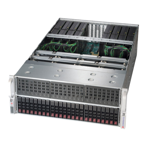
Page 87: Control Panel
SUPERSERVER 4027GR-TR/TRT USER'S MANUAL Figure 6-1. Front and Rear Chassis Views Control Panel Hard Drives (24) Power Supplies I/O Ports Power Supplies Control Panel The control panel is located on the front of the chassis. The LEDs inform you of system status. -
Page 88: Installing Hard Drives
Chapter 6: Advanced Chassis Setup Installing Hard Drives The SC418GTS supports a total of 24 hard disk drives, which are mounted in drive carriers and reside within the the hard drive bays. These drives are hot-swappable and can be removed or replaced without powering down the chassis. Enterprise SAS or SATA HDDs only are recommended. - Page 89 SUPERSERVER 4027GR-TR/TRT USER'S MANUAL Installing a Hard Drive into a Drive Carrier 1. Insert a drive into the carrier with the PCB side facing down and the connector end toward the rear of the carrier. 2. Align the drive in the carrier so that the screw holes of both line up. Note that there are holes in the carrier marked “SATA”...
-
Page 90: Accessing The Inside Of The System
Chapter 6: Advanced Chassis Setup Accessing the Inside of the System Removing the Chassis Cover You will need to access the inside of the system to complete certain procedures such as replacing fans. Removing the Chassis Cover If working with components such as memory, processors or heatsinks, start by shutting the system down and disconnecting the AC power cord. -
Page 91: Installing The Air Shroud
SUPERSERVER 4027GR-TR/TRT USER'S MANUAL Installing the Air Shroud Air Shrouds Air shrouds concentrate airfl ow to maximize fan effi ciency. Two air shrouds are included in the system: one for the CPUs and another for the PCI slots. The CPU air shroud, which sits behind the system fans, should be installed into the chassis fi... - Page 92 Chapter 6: Advanced Chassis Setup Installing the PCI-E Air Shroud 1. Remove the GPU retention bracket screw (located on the right side) and remove the GPU retention bracket. 2. Noting the front and rear sides of the air shroud, insert the sides of the air shroud between the chassis and GPU1 and GPU8.
-
Page 93: Cooling System
SUPERSERVER 4027GR-TR/TRT USER'S MANUAL Cooling System The SC418GTS chassis contains eight 9-cm system fans that provide cooling for the system. All eight fans are hot-swappable. There is no need to power down the system when switching fans. Changing a System Fan 1. -
Page 94: Power Supply
Chapter 6: Advanced Chassis Setup Power Supply The 4027GR-TR/TRT has four redundant, high-effi ciency 1600 Watt power supplies. These power supplies are auto-switching capable, enabling it to automatically sense and operate at a 100v to 240v input voltage. An amber light will be illuminated on the power supply when the power is off. - Page 95 SUPERSERVER 4027GR-TR/TRT USER'S MANUAL Notes 6-10...
-
Page 96: Chapter 7 Bios
Chapter 7: BIOS Chapter 7 BIOS Introduction This chapter describes the AMI BIOS setup utility for the X9DRG-O(T)F-CPU/ X9DRG-O-PCIE Platform. It also provides the instructions on how to navigate the AMI BIOS setup utility screens. The AMI ROM BIOS is stored in a Flash EEPROM and can be easily updated. -
Page 97: How To Change The Confi Guration Data
SUPERSERVER 4027GR-TR/TRT USER'S MANUAL How To Change the Confi guration Data The confi guration data that determines the system parameters may be changed by entering the AMI BIOS setup utility. This setup utility can be accessed by pressing <Delete> at the appropriate time during system boot. - Page 98 Chapter 7: BIOS The AMI BIOS main menu displays the following information: System Date This item displays the system date in Day MM/DD/YYYY format (e.g. Wed 01/15/2014). System Time This item displays the system time in HH:MM:SS format (e.g. 15:32:52). Supermicro X9DRG-O(T)F Version This item displays the SMC version of the BIOS ROM used in this system.
-
Page 99: Boot Feature
SUPERSERVER 4027GR-TR/TRT USER'S MANUAL Advanced Setup Confi gurations Use the arrow keys to select Advanced setup menu and press <Enter> to access the following submenu items. Boot Feature Quiet Boot This feature allows the user to select the bootup screen display between POST messages and the OEM logo. - Page 100 Chapter 7: BIOS Interrupt 19 Capture Interrupt 19 is the software interrupt that handles the boot disk function. When this item is set to Enabled, the ROM BIOS of the host adaptors will "capture" Interrupt 19 at bootup and allow the drives that are attached to these host adaptors to function as bootable disks.
- Page 101 SUPERSERVER 4027GR-TR/TRT USER'S MANUAL • CPU Signature • Microcode Patch • CPU Stepping • Max (Maximum) CPU Speed • Min (Minimum) CPU Speed • Processor Cores • Intel HT (Hyper-Threading) Technology • Intel VT-x Technology • Intel SMX Technology •...
- Page 102 Chapter 7: BIOS Hyper-threading Select Enabled to support Intel Hyper-threading Technology to enhance CPU per- formance. The options are Enabled and Disabled. Active Processor Cores Set to Enabled to use a processor's second core and above. (Please refer to Intel's website for more information.) The options are All, 1, 2, 3, 4, 5, 6, 7, 8, 9, 10, and 11.
- Page 103 SUPERSERVER 4027GR-TR/TRT USER'S MANUAL Intel ® Virtualization Technology (Available when supported by the CPU) Select Enabled to support Intel Virtualization Technology, which will allow one platform to run multiple operating systems and applications simultaneously in multiple partitions, creating multiple "virtual" systems in one physical computer.
- Page 104 Chapter 7: BIOS CPU C3 Report (Available when Power Technology is set to Custom) Select Enabled to allow the BIOS to report the CPU C3 State (ACPI C2) to the operating system. During the CPU C3 State, the CPU clock generator is turned off.
-
Page 105: North Bridge
SUPERSERVER 4027GR-TR/TRT USER'S MANUAL Recommended Short Duration Power Limit This item displays the short duration power settings (in watts) recommended by the manufacturer. Short Duration Power Limit This item displays the time period during which short duration power (in watts) is maintained. - Page 106 Chapter 7: BIOS MMCFG BASE This feature determines the lowest base address that can be assigned to PCI devices. The lower the address, the less system memory is available (for a 32-bit OS). The higher the address, the less resources are allocated to PCI devices. The options are 0x80000000, 0xA0000000, and 0xC0000000.
- Page 107 SUPERSERVER 4027GR-TR/TRT USER'S MANUAL QPI Confi guration Current QPI Link Speed This item displays the speed of the QPI Link. Current QPI Link Frequency This item displays the frequency of the QPI Link. Isoc Select Enabled to enable Isochronous support to meet QoS (Quality of Service) requirements.
- Page 108 Chapter 7: BIOS DIMM Information The status of a memory module is displayed as detected by the BIOS. Memory Mode When Independent is selected, all DIMMs are available to the operating system. When Mirroring is selected, the motherboard maintains two identical copies of all data in memory for data backup.
-
Page 109: South Bridge
SUPERSERVER 4027GR-TR/TRT USER'S MANUAL Data Scrambling Select Enabled to enable data scrambling to ensure data security and integrity. The options are Disabled and Enabled. Device Tagging Select Enabled to support device tagging which will allow the BIOS to tag a memory device that generates a stuck-bit or a hard error. - Page 110 Chapter 7: BIOS devices available for EFI (Extensive Firmware Interface) applications only. The settings are Disabled, Enabled and Auto. Port 60/64 Emulation Select Enabled to enable I/O port 60h/64h emulation support for a legacy USB keyboard to be supported by the operating system that does not recognize a legacy USB device.
- Page 111 SUPERSERVER 4027GR-TR/TRT USER'S MANUAL an active state when I/O activity resumes. The options are Enabled and Disabled. Port 0~5 Hot Plug Select Enabled to enable hot-plugging support for a particular port, which will allow the user to change a hardware component or device without shutting down the system.
- Page 112 Chapter 7: BIOS PCIe/PCI/PnP Confi guration Launch Storage OpROM Policy Use this feature to select the Option ROM to boot the system when there are multiple Option ROMs available in the system. The options are UEFI only and Legacy only. PCI Latency Timer Use this feature to set the latency timer of each PCI device installed on a PCI bus.
- Page 113 SUPERSERVER 4027GR-TR/TRT USER'S MANUAL CPU2 Slot1 PCI-E 3.0 x16 OPROM, CPU2 Slot2 PCI-E 3.0 x16 OPROM, CPU2 Slot3 PCI-E 3.0 x16 OPROM, CPU2 Slot4 PCI-E 3.0 x16 OPROM, CPU2 Slot5 PCI-E 3.0 x8 OPROM, CPU1 Slot6 PCI-E 3.0 x8 OPROM, PCI/PCIX/PCIe Slot7 OPROM, CPU1 Slot8 PCI-E 3.0 x16 OPROM, CPU1 Slot9 PCI-E 3.0...
- Page 114 Chapter 7: BIOS Serial Port 1 Confi guration Serial Port Select Enabled to enable a serial port specifi ed by the user. The options are En- abled and Disabled. Device Settings This item displays the settings of Serial Port 1. Change Settings This option specifi...
-
Page 115: Serial Port Console Redirection
SUPERSERVER 4027GR-TR/TRT USER'S MANUAL SOL Device Mode Use this feature to select the desired mode for a serial port specifi ed. The options are Normal and High Speed. Serial Port Console Redirection COM1/SOL These two submenus allow the user to confi gure the following console redirection settings for a COM Port specifi... - Page 116 Chapter 7: BIOS in transmission. Select Mark to add a mark as a parity bit to be sent along with the data bits. Select Space to add a Space as a parity bit to be sent with your data bits. The options are None, Even, Odd, Mark and Space. Stop Bits A stop bit indicates the end of a serial data packet.
- Page 117 SUPERSERVER 4027GR-TR/TRT USER'S MANUAL Serial Port for Out-of-Band Management/Windows Emergency Management Services (EMS) The submenu allows the user to confi gure console redirection settings to support Out-of-Band Serial Port management. Console Redirection Select Enabled to use a COM Port selected by the user for console redirection. The options are Enabled and Disabled.
-
Page 118: Acpi Settings
Chapter 7: BIOS ACPI Settings Use this feature to confi gure Advanced Confi guration and Power Interface (ACPI) power management settings for your system. ACPI Sleep State Use this feature to select the ACPI State when the system is in the sleep mode. Select S1 (CPU Stop Clock) to erase all CPU caches and stop executing instruc- tions. - Page 119 SUPERSERVER 4027GR-TR/TRT USER'S MANUAL Pending Operation Use this item to schedule an operation for the security device. The options are None, Enable Take Ownership, Disable Take Ownership, and TPM Clear. Note: During restart, the computer will reboot in order to execute the pend- ing operation and change the state of the security device.
-
Page 120: Event Logs
Chapter 7: BIOS VT Support: Intel Virtualization Technology support TPM Support: Trusted Platform support TPM State: Trusted Platform state ME Subsystem This feature displays the following ME Subsystem Confi guration settings. • ME BIOS Interface Version • ME Version Event Logs Use this feature to confi... - Page 121 SUPERSERVER 4027GR-TR/TRT USER'S MANUAL Memory Correctable Error Threshold This feature allows the user to enter the threshold value for correctable memory errors. The default setting is 10. PCI Error Logging Support Select Enabled to support error event logging for PCI slots. The options are Enabled and Disabled.
-
Page 122: Ipmi
Chapter 7: BIOS • Severity IPMI Use this feature to confi gure Intelligent Platform Management Interface (IPMI) settings. IPMI Firmware Revision This item indicates the IPMI fi rmware revision used in your system. IPMI Status This item indicates the status of the IPMI fi rmware installed in your system. ... - Page 123 SUPERSERVER 4027GR-TR/TRT USER'S MANUAL Select No to keep all system event logs after each system reboot. The options are No, Yes, On next reset, and Yes, On every reset. When SEL is Full This feature allows the user to decide what the BIOS should do when the system event log is full.
-
Page 124: Boot
Chapter 7: BIOS Gateway IP Address This item displays the Gateway IP address for this computer. This should be in decimal and in dotted quad form (i.e., 192.168.10.253). Boot This submenu allows the user to confi gure the following boot settings for the system. - Page 125 SUPERSERVER 4027GR-TR/TRT USER'S MANUAL UEFI OS Boot Priorities • 1st Device 7-30...
-
Page 126: Security
Chapter 7: BIOS Security This menu allows the user to confi gure the following security settings for the system. Password Check Use this feature to determine when a password entry is required. Select Setup for the user to enter a password only when entering setup. Select Always for the user to enter a password upon entering setup and at each system boot. -
Page 127: Save & Exit
SUPERSERVER 4027GR-TR/TRT USER'S MANUAL Save & Exit This submenu allows the user to confi gure the Save and Exit settings for the system. Discard Changes and Exit Select this option to quit the BIOS setup menu without making any permanent changes to the system confi... - Page 128 Chapter 7: BIOS Discard Changes Select this feature and press <Enter> to discard all the changes and return to the BIOS setup. When the dialog box appears, asking you if you want to load previ- ous values, select Yes to load the values previous saved, or select No to keep the changes you've made so far.
- Page 129 SUPERSERVER 4027GR-TR/TRT USER'S MANUAL Notes 7-34...
-
Page 130: Appendix A Bios Error Beep Codes
Appendix A: BIOS Error Beep Codes Appendix A BIOS Error Beep Codes During the POST (Power-On Self-Test) routines, which are performed at each system boot, errors may occur. Non-fatal errors are those which, in most cases, allow the system to continue to boot. - Page 131 SUPERSERVER 4027GR-TR/TRT USER'S MANUAL Notes...
-
Page 132: Appendix B System Specifi Cations
Appendix B: System Specifi cations Appendix B System Specifi cations Processors Two E5-4600 series processors in Socket R LGA 2011 type sockets Note: please refer to our website for details on supported processors. Chipset C602 chipset BIOS 16MB SPI Flash EEPROM with AMI® BIOS Memory Capacity Twenty four DIMM slots supporting up to 1.5 TB of LRDIMM. - Page 133 SUPERSERVER 4027GR-TR/TRT USER'S MANUAL Chassis SC418GTS-R3200B (4U rackmount) Dimensions: (WxHxD) 7 x 17.2 x 29 in. (178 x 437 x 737 mm) Weight Gross (Bare Bone): 100 lbs. (45.4 kg.) System Cooling The system has eight 9-cm hot-swappable cooling fans...
- Page 134 Appendix B: System Specifi cations Notes...
- Page 135 SUPERSERVER 4027GR-TR/TRT USER'S MANUAL (continued from front) The products sold by Supermicro are not intended for and will not be used in life support systems, medical equipment, nuclear facilities or systems, aircraft, aircraft devices, aircraft/emergency communication devices or other critical systems whose failure to perform be reasonably expected to result in signifi...