Table of Contents
Advertisement
Quick Links
Advertisement
Table of Contents

Related Manuals for Supero SuperServer 2027R-N3RF4+


Summary of Contents for Supero SuperServer 2027R-N3RF4+
- Page 1 UPER ® UPER ERVER 2027R-N3RF4+ 2027R-N3RFT+ USER’S MANUAL...
- Page 2 The information in this User’s Manual has been carefully reviewed and is believed to be accurate. The vendor assumes no responsibility for any inaccuracies that may be contained in this document, makes no commitment to update or to keep current the information in this manual, or to notify any person or organization of the updates.
-
Page 3: About This Manual
Preface Preface About This Manual This manual is written for professional system integrators and PC technicians. It provides information for the installation and use of the SuperServer 2027R- N3RF4+/2027R-N3RFT+. Installation and maintenance should be performed by experienced technicians only. Manual Organization Chapter 1: Introduction The first chapter provides a checklist of the main components included with the serv- er system and describes the main features of the X9DRW-3LN4F+/X9DRW-3TF+... - Page 4 UPER ERVER 2027R-N3RF4+/2027R-N3RFT+ User's Manual Chapter 5: Advanced Serverboard Setup Chapter 5 provides detailed information on the X9DRW-3LN4F+/X9DRW-3TF+ serverboard, including the locations and functions of connections, headers and jumpers. Refer to this chapter when adding or removing processors or main memory and when reconfiguring the serverboard.
- Page 5 Preface Notes...
-
Page 6: Table Of Contents
UPER ERVER 2027R-N3RF4+/2027R-N3RFT+ User's Manual Table of Contents Chapter 1 Introduction Overview ......................1-1 Serverboard Features ..................1-2 Processors ...................... 1-2 Memory ......................1-2 Onboard SAS ....................1-2 Onboard Serial ATA ..................1-2 Rear I/O Ports ....................1-2 Graphics Controller ..................1-3 Server Chassis Features ................ - Page 7 Table of Contents Chapter 3 System Interface Overview ......................3-1 Control Panel Buttons ..................3-1 Reset ....................... 3-1 Power ......................3-1 Control Panel LEDs ..................3-1 NIC1 ........................ 3-2 NIC2 ........................ 3-2 HDD ......................... 3-2 Power ......................3-2 Drive Carrier LEDs ..................3-3 Power Failure ....................
- Page 8 ERVER 2027R-N3RF4+/2027R-N3RFT+ User's Manual 5-11 SAS/SATA Port Connections ................. 5-26 5-12 Installing Software ..................5-27 Supero Doctor III ................... 5-28 Chapter 6 Advanced Chassis Setup Static-Sensitive Devices .................. 6-1 Precautions ..................... 6-1 Control Panel ....................6-2 System Fans ....................6-3 System Fan Failure ..................
-
Page 9: Chapter 1 Introduction
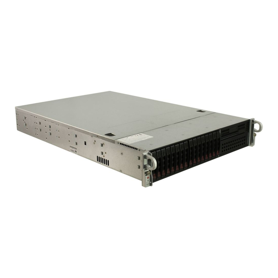
Chapter 1: Introduction Chapter 1 Introduction Overview The SuperServer 2027R-N3RF4+/2027R-N3RFT+ is a high-end server comprised of two main subsystems: the SC219A-R920WB 2U server chassis and the X9DRW- 3LN4F+/X9DRW-3TF+ dual processor serverboard. Please refer to our web site for information on operating systems that have been certified for use with the system (www.supermicro.com). -
Page 10: Serverboard Features
UPER ERVER 2027R-N3RF4+/2027R-N3RFT+ User's Manual Serverboard Features At the heart of the SuperServer 2027R-N3RF4+/2027R-N3RFT+ lies the X9DRW- 3LN4F+/X9DRW-3TF+, a dual processor serverboard based on the Intel® C606 chipset. Below are the main features of the serverboard. (See Figure 1-1 for a block diagram of the chipset.) Processors The X9DRW-3LN4F+/X9DRW-3TF+ supports single or dual Intel®... -
Page 11: Graphics Controller
Chapter 1: Introduction Graphics Controller The X9DRW-3LN4F+/X9DRW-3TF+ features an integrated G200 (Renesas SH7757 BMC) graphics chip. Server Chassis Features The 2027R-N3RF4+/2027R-N3RFT+ is built upon the SC219A-R920WB chassis. Details on the chassis and on servicing procedures can be found in Chapter 6.The following is a general outline of the main features of the chassis. -
Page 12: System Block Diagram
UPER ERVER 2027R-N3RF4+/2027R-N3RFT+ User's Manual Figure 1-1. Intel C606 Chipset: System Block Diagram Note: This is a general block diagram. Please see Chapter 5 for details. Powerville / Twinville L3 / L4 To WIO Riser Card PE3 PE2 CPU REAR LEFT WIO RIGHT WIO Socket 01... -
Page 13: Contacting Supermicro
Chapter 1: Introduction Contacting Supermicro Headquarters Address: Super Micro Computer, Inc. 980 Rock Ave. San Jose, CA 95131 U.S.A. Tel: +1 (408) 503-8000 Fax: +1 (408) 503-8008 Email: marketing@supermicro.com (General Information) support@supermicro.com (Technical Support) Web Site: www.supermicro.com Europe Address: Super Micro Computer B.V. Het Sterrenbeeld 28, 5215 ML 's-Hertogenbosch, The Netherlands Tel:... - Page 14 UPER ERVER 2027R-N3RF4+/2027R-N3RFT+ User's Manual Notes...
-
Page 15: Chapter 2 Server Installation
Chapter 2: Server Installation Chapter 2 Server Installation Overview This chapter provides a quick setup checklist to get your 2027R-N3RF4+/2027R- N3RFT+ up and running. Following these steps in the order given should enable you to have the system operational within a minimum amount of time. This quick setup assumes that your system has come to you with the processors and memory pre-installed. -
Page 16: Warnings And Precautions
UPER ERVER 2027R-N3RF4+/2027R-N3RFT+ User's Manual installation only in a Restricted Access Location (dedicated equipment rooms, service closets and the like). • This product is not suitable for use with visual display work place devices acccording to §2 of the the German Ordinance for Work with Visual Display Units. -
Page 17: Rack Mounting Considerations
Chapter 2: Server Installation Rack Mounting Considerations Ambient Operating Temperature If installed in a closed or multi-unit rack assembly, the ambient operating tempera- ture of the rack environment may be greater than the ambient temperature of the room. Therefore, consideration should be given to installing the equipment in an environment compatible with the manufacturer’s maximum rated ambient tempera- ture (Tmra). -
Page 18: Installing The System Into A Rack
UPER ERVER 2027R-N3RF4+/2027R-N3RFT+ User's Manual Installing the System into a Rack This section provides information on installing the 2027R-N3RF4+/2027R-N3RFT+ into a rack unit with the rack rails provided. There are a variety of rack units on the market, which may mean the assembly procedure will differ slightly. You should also refer to the installation instructions that came with the rack unit you are using. -
Page 19: The Inner Rail Extensions
Chapter 2: Server Installation Inner Rails (Pre-installed on the chassis) Figure 2-2. Inner Rail Extensions The Inner Rail Extensions The inner rails are pre-attached and do not interfere with normal use of the chas- sis if you decide not to use a server rack. When using a rack, attach the inner rail extension to the inner rail to stabilize the chassis within the rack. -
Page 20: Outer Rack Rails
UPER ERVER 2027R-N3RF4+/2027R-N3RFT+ User's Manual Figure 2-3. Extending and Releasing the Outer Rails Outer Rack Rails Outer rails attach to the server rack and hold the chassis in place. The SC213 comes equipped with quick-release outer rails that allow the chassis to be easily extended or removed from the rack. -
Page 21: Attaching The Outer Rack Rails To The Rack
Chapter 2: Server Installation Figure 2-3. Extending and Releasing the Outer Rails Attaching the Outer Rack Rails to the Rack The outer rails attach to the rack and allow easy access to the chassis. Installing the Outer Rails to the Rack 1. - Page 22 UPER ERVER 2027R-N3RF4+/2027R-N3RFT+ User's Manual Figure 2-4. Installing into a Rack Installing the Chassis into a Rack 1. Confirm that the inner rails (A) and rail extensions (B) are properly installed. Confirm that the outer rails (C) and outer rail extensions (D) are correctly installed on the rack.
- Page 23 Chapter 2: Server Installation Figure 2-5. Securing the Chassis to the Rack...
- Page 24 UPER ERVER 2027R-N3RF4+/2027R-N3RFT+ User's Manual Notes 2-10...
-
Page 25: Chapter 3 System Interface
Chapter 3: System Interface Chapter 3 System Interface Overview There are several LEDs on the control panel as well as others on the hard drive carriers to keep you constantly informed of the overall status of the system as well as the activity and health of specific components. -
Page 26: Nic1
UPER ERVER 2027R-N3RF4+/2027R-N3RFT+ User's Manual This section explains what each LED indicates when illuminated and any corrective action you may need to take. NIC1 Indicates network activity on LAN1 when flashing . NIC2 Indicates network activity on LAN2 when flashing. Indicates IDE channel activity. -
Page 27: Drive Carrier Leds
Chapter 3: System Interface Power Failure When this LED flashes, it indicates a power failure in the power supply. Overheat/Fan Fail When this LED flashes it indicates a fan failure. When continuously on (not flashing) it indicates an overheat condition, which may be caused by cables obstructing the airflow in the system or the ambient room temperature being too warm. - Page 28 UPER ERVER 2027R-N3RF4+/2027R-N3RFT+ User's Manual Notes...
-
Page 29: Chapter 4 System Safety
Chapter 4: System Safety Chapter 4 System Safety Electrical Safety Precautions Basic electrical safety precautions should be followed to protect yourself from harm and the SuperServer 2027R-N3RF4+/2027R-N3RFT+ from damage: • Be aware of the locations of the power on/off switch on the chassis as well as the room's emergency power-off switch, disconnection switch or electrical outlet. -
Page 30: General Safety Precautions
UPER ERVER 2027R-N3RF4+/2027R-N3RFT+ User's Manual supply cord. Disconnect both power supply cords before servicing to avoid electrical shock • Serverboard Battery: CAUTION - There is a danger of explosion if the onboard battery is installed upside down, which will reverse its polarites (see Figure 4-1). This battery must be replaced only with the same or an equivalent type recom- mended by the manufacturer (CR2032). -
Page 31: Esd Precautions
Chapter 4: System Safety • Remove any jewelry or metal objects from your body, which are excellent metal conductors that can create short circuits and harm you if they come into contact with printed circuit boards or areas where power is present. •... -
Page 32: Operating Precautions
UPER ERVER 2027R-N3RF4+/2027R-N3RFT+ User's Manual Operating Precautions Care must be taken to assure that the chassis cover is in place when the 2027R- N3RF4+/2027R-N3RFT+ is operating to assure proper cooling. Out of warranty damage to the system can occur if this practice is not strictly followed. Figure 4-1. -
Page 33: Chapter 5 Advanced Serverboard Setup
Chapter 5: Advanced Serverboard Setup Chapter 5 Advanced Serverboard Setup This chapter covers the steps required to install processors and heatsinks to the X9DRW-3LN4F+/X9DRW-3TF+ serverboard, connect the data and power cables and install add-on cards. All serverboard jumpers and connections are described and a layout and quick reference chart are included in this chapter. -
Page 34: Installing The Processor And Heatsink
UPER ERVER 2027R-N3RF4+/2027R-N3RFT+ User's Manual Installing the Processor and Heatsink When handling the processor package, avoid placing direct pressure on the label area of the fan. Notes: • Always connect the power cord last and always remove it before adding, re- moving or changing any hardware components. - Page 35 Chapter 5: Advanced Serverboard Setup 3. With the lever labeled 'Close 1st' fully retracted, gently push down on the 'Open 1st' lever to open the load plate. Lift the load plate to open it completely. Gently push 4. Using your thumb and the index down to pop the load plate finger, remove the 'WARNING'...
- Page 36 UPER ERVER 2027R-N3RF4+/2027R-N3RFT+ User's Manual Warning: You can only install the CPU to the socket in one direction. Make sure that the CPU is properly inserted into the socket before closing the load plate. If it doesn't close properly, do not force it as it may damage your CPU.
-
Page 37: Installing A Cpu Heatsink
Chapter 5: Advanced Serverboard Setup Installing a CPU Heatsink 1. Place the heatsink on top of the CPU, referring to Figure 5-1 for correct orien- tation. An incorrect heatsink orientation will interfere with the add-on cards. 2. Screw in two diagonal screws until just snug (do not over-tighten the screws, which may damage the CPU.) 3. -
Page 38: Connecting Cables
UPER ERVER 2027R-N3RF4+/2027R-N3RFT+ User's Manual Connecting Cables Now that the processors are installed, the next step is to connect the cables to the serverboard. Connecting Data Cables The cables used to transfer data from the peripheral devices have been carefully routed in preconfigured systems to prevent them from blocking the flow of cooling air that moves through the system from front to back. -
Page 39: I/O Ports
Chapter 5: Advanced Serverboard Setup Figure 5-2. Front Control Panel Header Pins (JF1) Ground x (key) x (key) Power LED 3.3V HDD LED UID Switch/Vcc NIC1 Link LED NIC1 Active LED NIC2 Link LED NIC2 Active LED Blue: OH/Fan Fail/Power Fail/UID LED Red: (Blue LED Cathode) Power Fail LED 3.3V... -
Page 40: Installing Memory
UPER ERVER 2027R-N3RF4+/2027R-N3RFT+ User's Manual Installing Memory Note: Check the Supermicro web site for recommended memory modules. CAUTION Exercise extreme care when installing or removing DIMM modules to prevent any possible damage. Installing DIMMs 1. Insert the desired number of DIMMs into the memory slots, starting with slot P1-DIMMA1. - Page 41 Chapter 5: Advanced Serverboard Setup Processor & Memory Module Population Configuration For memory to work properly, follow the tables below for memory installation. Processors and their Corresponding Memory Modules CPU# Corresponding DIMM Modules CPU 1 CPU2 Processor and Memory Module Population Number of CPU and Memory Population Configuration Table CPUs+DIMMs...
- Page 42 UPER ERVER 2027R-N3RF4+/2027R-N3RFT+ User's Manual UDIMM Support DIMMs Populated per UDIMM Type POR Speeds (in Ranks per DIMM DDR Channel (Unb. DIMM) MHz) (Any Combination) ECC/Non-ECC DDR3 1066, 1333 SR, DR ECC/Non-ECC DDR3 1066, 1333 SR, DR RDIMM Support DIMMs Populated per RDIMM Type POR Speeds (in Ranks per DIMM...
-
Page 43: Adding Pci Cards
Chapter 5: Advanced Serverboard Setup Adding PCI Cards PCI Expansion Slots Riser cards installed to the system allow you to add PCI expansion cards (see below). The 2027R-N3RF4+/2027R-N3RFT+ can support the use of two standard size (full-height), two low-profile and two full-height, half-length expansion cards (with pre-installed riser cards). -
Page 44: Serverboard Details
UPER ERVER 2027R-N3RF4+/2027R-N3RFT+ User's Manual Serverboard Details Figure 5-5. SUPER X9DRW-3TF+/X9DRW-3TF+ Layout LAN4 LAN3 LAN1 LAN2 VGA1 COM1 JUIDB1 KB/MOUSE USB0/1 Buzzer IPMI_LAN CTRL 1 SXB1B CTRL 2 X9DRW-3LN4F+ Rev. 1.20 LEM1 CPU2 CTRL BATTERY CPLD JBAT1 JBT1 Clock Intel CPU1 JPW2 I-SATA5... -
Page 45: X9Drw-3Ln4F+/X9Drw-3Tf+ Quick Reference
Chapter 5: Advanced Serverboard Setup X9DRW-3LN4F+/X9DRW-3TF+ Quick Reference Jumper Description Default Setting JBT1 Clear CMOS See Section 5-9 SMB to PCI-E Slots Pins 2-3 (Normal) JPB1 BMC Enable/Disable Pins 1-2 (Enabled) JPG1 VGA Enable/Disable Pins 1-2 (Enabled) JPL1 LAN1/LAN2 Enable/Disable Pins 1-2 (Enabled) JPL2 LAN3/LAN4 Enable/Disable... - Page 46 UPER ERVER 2027R-N3RF4+/2027R-N3RFT+ User's Manual Onboard Buzzer (Internal Speaker) SXB1A/1B/1C SMC-Proprietary WIO_L (Left) Add-On Card Slot SXB2 SMC-Proprietary WIO_R (Right) Add-On Card Slot T-SGPIO 1/2 Serial-Link General_Purpose IO Headers (J17/J18) USB 0/1 Rear I/O USB 0/1 Ports USB 2/3, 4/5 Front Accessible USB 2/3, 4/5 Headers USB 6 Front Panel Type A USB 6 Port...
-
Page 47: Connector Definitions
Chapter 5: Advanced Serverboard Setup Connector Definitions ATX Power 24-pin Connector Pin Definitions ATX Power Connector Pin# Definition Pin # Definition +3.3V +3.3V The primary ATX power supply con- -12V +3.3V nector meets the SSI EPS 12V speci- fication. Make sure that the orientation PS_ON of the connector is correct. - Page 48 UPER ERVER 2027R-N3RF4+/2027R-N3RFT+ User's Manual NMI Button NMI Button Pin Definitions (JF1) The non-maskable interrupt button Pin# Definition header is located on pins 19 and 20 Control of JF1. Refer to the table on the right Ground for pin definitions. Power LED Power LED Pin Definitions (JF1)
- Page 49 Chapter 5: Advanced Serverboard Setup Overheat (OH)/Fan Fail/PWR Fail/ OH/Fan Fail/ PWR Fail/Blue_UID UID LED LED Pin Definitions (JF1) Pin# Definition Connect an LED to pins 7 and 8 of Blue_LED Cathode (UID) JF1 to provide advanced warning of chassis overheating or fan failure. OH/Fan Fail/PWR Fail/UID LED These pins also work with the front OH/Fan Fail/PWR Fail LED Status...
-
Page 50: Chassis Intrusion
UPER ERVER 2027R-N3RF4+/2027R-N3RFT+ User's Manual Fan Headers The serverboard has six system/ Fan Header Pin Definitions CPU fan headers (Fan 1~Fan 5, Fan Pin# Definition A). All are 4-pin fans headers, which Ground are backward compatible with tradi- +12V tional 3-pin fans. Fan speed control is Tachometer available for 4-pin fans only. - Page 51 Chapter 5: Advanced Serverboard Setup TPM Header/Port 80 TPM/Port 80 Header Pin Definitions A Trusted Platform Module/Port 80 Pin # Definition Pin # Definition header is located at JTPM1 to provide LCLK TPM support and Port 80 connection. LFRAME# <(KEY)> Use this header to enhance system LRESET# +5V (X)
- Page 52 UPER ERVER 2027R-N3RF4+/2027R-N3RFT+ User's Manual T-SGPIO 1/2 Headers T-SGPIO Pin Definitions Two SGPIO (Serial-Link General Pin# Definition Definition Purpose Input/Output) headers are located at J17 and J18. These head- Ground Data ers support Serial Link interface for Load Ground onboard SATA connections. See the Clock table on the right for pin definitions.
- Page 53 Chapter 5: Advanced Serverboard Setup Unit Identifier Switch The UID Switch is located next to the 10G LAN 4 port on the backplane. The rear UID LED (LE2) is located next to the UID Switch. The Front Panel UID LED is located at Pins 7/8 UID Switch of the Front Control Panel at JF1.
-
Page 54: Serial Ports
UPER ERVER 2027R-N3RF4+/2027R-N3RFT+ User's Manual Serial Ports Serial COM) Ports Pin Definitions Two COM connections (COM1 & Pin # Definition Pin # Definition COM2) are located on the serverboard. COM1 is located on the Backplane I/O panel. COM2, located close to USB 4/5 Connectors, is used to provide front access support. -
Page 55: Jumper Settings
Chapter 5: Advanced Serverboard Setup Jumper Settings Explanation of Jumpers To modify the operation of the serverboard, jumpers can be used Connector to choose between optional settings. Pins Jumpers create shorts between two pins to change the function of the Jumper connector. - Page 56 UPER ERVER 2027R-N3RF4+/2027R-N3RFT+ User's Manual JPL1/JPL2 LAN Port Use JPL1 to enable/disable LAN ports Jumper Settings 1/2, and use JPL2 for LAN ports Jumper Setting Definition 3/4. See the table on the right for Pins 1-2 Enabled jumper settings. The default setting Pins 2-3 Disabled is Enabled.
-
Page 57: 5-10 Onboard Indicators
Chapter 5: Advanced Serverboard Setup 5-10 Onboard Indicators Activity LED Link LED LAN LEDs The Ethernet ports (located beside the VGA port) have two LEDs. On each LAN LED Gigabit LAN port, one LED indicates Connection Speed Indicator activity when blinking while the other LED Color Definition LED may be green, amber or off to... -
Page 58: 5-11 Sas/Sata Port Connections
UPER ERVER 2027R-N3RF4+/2027R-N3RFT+ User's Manual 5-11 SAS/SATA Port Connections SATA Port Pin Definitions Pin # Definition SATA Ports Ground There are six Serial ATA Ports (I- SATA0 ~I - SATA 5) located on the serverboard, including four SATA2 Ground ports and two SATA3 ports. See the table on the right for pin definitions. -
Page 59: 5-12 Installing Software
Chapter 5: Advanced Serverboard Setup 5-12 Installing Software After the hardware has been installed, you should first install the operating system and then the drivers. The necessary drivers are all included on the Supermicro CDs that came packaged with your serverboard. Driver/Tool Installation Display Screen Note: Click the icons showing a hand writing on paper to view the readme files for each item. -
Page 60: Supero Doctor Iii
ERVER 2027R-N3RF4+/2027R-N3RFT+ User's Manual Supero Doctor III The Supero Doctor III program is a Web base management tool that supports remote management capability. It includes Remote and Local Management tools. The local management is called SD III Client. The Supero Doctor III program included on the CDROM that came with your serverboard allows you to monitor the environment and operations of your system. - Page 61 Chapter 5: Advanced Serverboard Setup Supero Doctor III Interface Display Screen (Remote Control) Note: SD III Software Revision 1.0 can be downloaded from our Web Site at: ftp:// ftp.supermicro.com/utility/Supero_Doctor_III/. You can also download SDIII User's Guide at: http://www.supermicro.com/manuals/other/SDIII_User_Guide.pdf. For Linux, we will still recommend Supero Doctor II.
- Page 62 UPER ERVER 2027R-N3RF4+/2027R-N3RFT+ User's Manual Notes 5-30...
-
Page 63: Chapter 6 Advanced Chassis Setup
Chapter 6: Advanced Chassis Setup Chapter 6 Advanced Chassis Setup This chapter covers the steps required to install components and perform mainte- nance on the SC219 chassis. For component installation, follow the steps in the order given to eliminate the most common problems encountered. If some steps are unnecessary, skip ahead to the next step. -
Page 64: Control Panel
UPER ERVER 2027R-N3RF4+/2027R-N3RFT+ User's Manual Figure 6-1. Chassis: Front and Rear Views Slim DVD-ROM (optional) Control Panel SATA Drive Bays (4) Power Supplies IPMI LAN USB Ports VGA Port PCI Expansion Slots (w/riser card) Mouse/Keyboard Ports COM1 Port 1G Ethernet Ports 10G Ethernet Ports Note: the 10G Ethernet ports are included on the 2027R-N3RFT+ only. -
Page 65: System Fans
Chapter 6: Advanced Chassis Setup System Fans Four 8-cm hot-swap fans provide the cooling for the 2027R-N3RF4+/2027R- N3RFT+. These fans are located on the front side of the fan bracket. In addition, three optional fans may be placed on the rear side of the fan bracket for cooling redundancy. - Page 66 UPER ERVER 2027R-N3RF4+/2027R-N3RFT+ User's Manual Figure 6-3. Installing a Front System Fan...
-
Page 67: Air Shroud
Chapter 6: Advanced Chassis Setup Air Shroud Air shrouds concentrate airflow to maximize fan efficiency. The SC219 chassis air shroud does not require screws for installation. Installing the Air Shroud 1. Lay the chassis on a flat, stable surface and remove the chassis cover. 2. -
Page 68: Accessing The Drive Bays
UPER ERVER 2027R-N3RF4+/2027R-N3RFT+ User's Manual Accessing the Drive Bays SATA Drives: Because of their hotswap capability, you do not need to access the inside of the chassis or power down the system to install or replace the SATA drives. Proceed to the next section for instructions. DVD-ROM Drive: For installing/removing a DVD-ROM drive, you will need to gain access to the inside of the 2027R-N3RF4+/2027R-N3RFT+ by removing the top cover of the chassis. - Page 69 Chapter 6: Advanced Chassis Setup Figure 6-5. Mounting a Drive in a Carrier Figure 6-6. Removing Hard Drive Tray...
-
Page 70: Hard Drive Backplane
UPER ERVER 2027R-N3RF4+/2027R-N3RFT+ User's Manual Hard Drive Backplane The hard drives plug into a backplane that provides power and drive ID. A RAID controller can be used with the backplane to provide data security. The operating system you use must have RAID support to enable the hot-swap capability of the drives. -
Page 71: Power Supply
Chapter 6: Advanced Chassis Setup Power Supply The SuperServer 2027R-N3RF4+/2027R-N3RFT+ has a 920 watt redundant power supply consisting of two power modules. Each power supply module has an auto- switching capability, which enables it to automatically sense and operate at a 100V - 240V input voltage. - Page 72 UPER ERVER 2027R-N3RF4+/2027R-N3RFT+ User's Manual Figure 6-7. Removing the Power Supply Release Tab 6-10...
-
Page 73: Chapter 7 Bios
Chapter 7: BIOS Chapter 7 BIOS Introduction This chapter describes the AMI BIOS Setup utility for the X9DRW-3LN4F+/X9DRW- 3TF+. It also provides the instructions on how to navigate the AMI BIOS Setup utility screens. The AMI ROM BIOS is stored in a Flash EEPROM and can be easily updated. -
Page 74: How To Change The Configuration Data
UPER ERVER 2027R-N3RF4+/2027R-N3RFT+ User's Manual How To Change the Configuration Data The configuration data that determines the system parameters may be changed by entering the AMI BIOS Setup utility. This Setup utility can be accessed by pressing <F2> at the appropriate time during system boot. Note: For AMI UEFI BIOS Recovery, please refer to the UEFI BIOS Re- covery User Guide posted @http://www.supermicro.com/support/manuals/. - Page 75 Chapter 7: BIOS The AMI BIOS main menu displays the following information: System Date This item displays the system date in Day MM/DD/YY format (e.g. Wed 10/12/2011). System Time This item displays the system time in HH:MM:SS format (e.g. 15:32:52). Supermicro X9DRW-3LN4F+/X9DRW-3TF+ Version This item displays the SMC version of the BIOS ROM used in this system.
-
Page 76: Advanced Setup Configurations
UPER ERVER 2027R-N3RF4+/2027R-N3RFT+ User's Manual Advanced Setup Configurations Use the arrow keys to select Advanced and press <Enter> to access the following submenu items. Boot Features Quiet Boot This feature allows the user to select bootup screen display between POST mes- sages and the OEM logo. -
Page 77: Power Configuration
Chapter 7: BIOS Interrupt 19 Capture Interrupt 19 is the software interrupt that handles the boot disk function. When this item is set to Enabled, the ROM BIOS of the host adaptors will "capture" Interrupt 19 at bootup and allow the drives that are attached to these host adaptors to function as bootable disks. - Page 78 UPER ERVER 2027R-N3RF4+/2027R-N3RFT+ User's Manual • CPU Stepping • Maximum CPU Speed • Minimum CPU Speed • Processor Cores • Intel HT (Hyper-Threading) Technology • Intel VT-x Technology • Intel SMX Technology • L1 Data Cache • L1 Code Cache •...
- Page 79 Chapter 7: BIOS Active Processor Cores Set to Enabled to use a processor's second core and above. (Please refer to Intel's website for more information.) The options are All, 1, 2, 4 and 6. Limit CPUID Maximum This feature allows the user to set the maximum CPU ID value. Enable this function to boot the legacy operating systems that cannot support processors with extended CPUID functions.
-
Page 80: Cpu Power Management Configuration
UPER ERVER 2027R-N3RF4+/2027R-N3RFT+ User's Manual Intel® Virtualization Technology (Available when supported by the CPU) Select Enabled to support Intel Virtualization Technology, which will allow one platform to run multiple operating systems and applications in independent parti- tions, creating multiple "virtual" systems in one physical computer. The options are Enabled and Disabled. - Page 81 Chapter 7: BIOS CPU C6 Report (Available when Power Technology is set to Custom) Select Enabled to allow the BIOS to report the CPU C6 State (ACPI C3) to the operating system. During the CPU C6 State, the power to all cache is turned off.
-
Page 82: Chipset Configuration
UPER ERVER 2027R-N3RF4+/2027R-N3RFT+ User's Manual Short Duration Power Limit This item displays the time period during which short duration power is main- tained. Chipset Configuration North Bridge This feature allows the user to configure the settings for the Intel North Bridge. Integrated IO Configuration Intel VT-d Select Enabled to enable Intel Virtualization Technology support for Direct I/O... -
Page 83: Qpi Configuration
Chapter 7: BIOS IOU3-PCIe Port This feature allows the user to set the bus speed between the IOU3 and the PCI-Exp port. The options are x4x4x4x4, x4x4x8, x8x4x4, x8x8, x16, and Auto. IIO 2 PCIe Port Bifurcation Control This submenu configures the following IO PCIe Port Bifurcation Control settings for IIO 2 PCIe ports to determine how the available PCI-Express lanes to be distributed between the PCI-Exp. -
Page 84: Dimm Configuration
UPER ERVER 2027R-N3RF4+/2027R-N3RFT+ User's Manual DIMM Configuration This section displays the following DIMM information. Current Memory Mode This item displays the current memory mode. Current Memory Speed This item displays the current memory speed. Mirroring This item displays if memory mirroring is supported by the motherboard. Memory mirroring creates a duplicate copy of the data stored in the memory to enhance data security. - Page 85 Chapter 7: BIOS Channel Interleaving This feature selects from the different channel interleaving methods. The options are Auto, 1 Way, 2 Way, 3, Way, and 4 Way. Rank Interleaving This feature allows the user to select a rank memory interleaving method. The options are Auto, 1 Way, 2 Way, 4, Way, and 8 Way.
-
Page 86: South Bridge Configuration
UPER ERVER 2027R-N3RF4+/2027R-N3RFT+ User's Manual South Bridge Configuration This feature allows the user to configure the settings for the Intel PCH chip. PCH Information This feature displays the following PCH information. Name: This item displays the name of the PCH chip. Stepping: This item displays the status of the PCH stepping. -
Page 87: Sata Configuration
Chapter 7: BIOS SATA Configuration When this submenu is selected, the AMI BIOS automatically detects the presence of IDE or SATA devices and displays the following items. SATA Port0~SATA Port5: The AMI BIOS displays the status of each SATA port as detected by the BIOS. - Page 88 UPER ERVER 2027R-N3RF4+/2027R-N3RFT+ User's Manual RAID Mode The following items are displayed when RAID Mode is selected: Port 0~5 Hot Plug Select Enabled to enable hot-plug support for the particular port. The options are Enabled and Disabled. SCU (Storage Control Unit) Configuration Storage Controller Unit Select Enabled to enable PCH SCU storage devices.
- Page 89 Chapter 7: BIOS SERR# Generation Select Enabled to allow a PCI device to generate an SERR number for a PCI Bus Signal Error Event. The options are Enabled and Disabled. Maximum Payload Select Auto to allow the system BIOS to automatically set the maximum payload value for a PCI-E device to enhance system performance.
-
Page 90: Super Io Configuration
UPER ERVER 2027R-N3RF4+/2027R-N3RFT+ User's Manual Super IO Configuration Super IO Chip: This item displays the Super IO chip used in the motherboard. Serial Port 1 Configuration Serial Port Select Enabled to enable a serial port specified by the user. The options are En- abled and Disabled. -
Page 91: Serial Port Console Redirection
Chapter 7: BIOS Serial Port 2 Attribute Use this feature to select the attribute for serial port 2. The options are SOL (Serial On LAN), and COM. Serial Port Console Redirection COM 1/COM 2/SOL These two submenus allow the user to configure the following Console Redirection settings for a COM Port specified by the user. - Page 92 UPER ERVER 2027R-N3RF4+/2027R-N3RFT+ User's Manual in transmission. Select Mark to add a mark as a parity bit to be sent along with the data bits. Select Space to add a Space as a parity bit to be sent with your data bits.
-
Page 93: Acpi Settings
Chapter 7: BIOS Console Redirection Select Enabled to use a COM Port selected by the user for Console Redirection. The options are Enabled and Disabled. Console Redirection Settings This feature allows the user to specify how the host computer will exchange data with the client computer, which is the remote computer used by the user. -
Page 94: Tpm Enable Status
UPER ERVER 2027R-N3RF4+/2027R-N3RFT+ User's Manual to use power-reduced mode. Power will only be supplied to limited components (such as RAMs) to maintain the most critical functions of the system. The options are S1 (CPU_Stop_Clock), and Suspend Disabled. NUMA (NON-Uniform Memory Access) This feature enables the Non-Uniform Memory Access ACPI support. - Page 95 Chapter 7: BIOS TPM Owner Status This item displays the status of TPM Ownership. Intel TXT (LT-SX) Configuration Intel TXT (LT-SX) Hardware Support This feature indicates if the following hardware components support the Intel Trusted Execution Technology. CPU: TXT (Trusted Execution Technology) Feature Chipset: TXT (Trusted Execution Technology) Feature Intel TXT (LT-SX) Configuration This feature displays the following TXT configuration setting.
-
Page 96: Nic Configuration
UPER ERVER 2027R-N3RF4+/2027R-N3RFT+ User's Manual NIC Configuration Link Speed Use this feature to change the link speed and duplex for the current port. The op- tions are AutoNeg, 10Mbps Half, 10Mbps Full, 100Mbps Half, and 100Mbps full. Wake on LAN Select enabled to wake the system with a magic packet. -
Page 97: Event Logs
Chapter 7: BIOS Event Logs Use this feature to configure Event Log settings. Change SMBIOS Event Log Settings This feature allows the user to configure SMBIOS Event settings. Enabling/Disabling Options SMBIOS Event Log Select Enabled to enable SMBIOS (System Management BIOS) Event Logging during system boot. - Page 98 UPER ERVER 2027R-N3RF4+/2027R-N3RFT+ User's Manual Erasing Settings Erase Event Log Select Enabled to erase the SMBIOS (System Management BIOS) Event Log, which is completed before a event logging is initialized upon system reboot. The options are No and Yes. When Log is Full Select Erase Immediately to immediately erase SMBIOS error event logs that ex- ceed the limit when the SMBIOS event log is full.
-
Page 99: Ipmi
Chapter 7: BIOS IPMI Use this feature to configure Intelligent Platform Management Interface (IPMI) settings. IPMI Firmware Revision This item indicates the IPMI firmware revision used in your system. IPMI Status This item indicates the status of the IPMI firmware installed in your system. System Event Log ... -
Page 100: Bmc Network Configuration
UPER ERVER 2027R-N3RF4+/2027R-N3RFT+ User's Manual When SEL is Full This feature allows the user to decide what the BIOS should do when the system event log is full. Select Erase Immediately to erase all events in the log when the system event log is full. -
Page 101: Boot
Chapter 7: BIOS Gateway IP Address This item displays the Gateway IP address for this computer. This should be in decimal and in dotted quad form (i.e., 192.168.10.253). Boot This submenu allows the user to configure the following boot settings for the system. -
Page 102: Security
UPER ERVER 2027R-N3RF4+/2027R-N3RFT+ User's Manual Security This menu allows the user to configure the following security settings for the system. Administrator Password Use this feature to set the Administrator Password which is required to enter the BIOS setup utility. The length of the password should be from 3 characters to 8 characters long. -
Page 103: Save & Exit
Chapter 7: BIOS Save & Exit This submenu allows the user to configure the Save and Exit settings for the system. Discard Changes and Exit Select this option to quit the BIOS Setup without making any permanent changes to the system configuration, and reboot the computer. Select Discard Changes and Exit, and press <Enter>. - Page 104 UPER ERVER 2027R-N3RF4+/2027R-N3RFT+ User's Manual Discard Changes Select this feature and press <Enter> to discard all the changes and return to the BIOS setup. When the dialog box appears, asking you if you want to load previ- ous values, click Yes to load the values previous saved, or click No to keep the changes you've made so far.
-
Page 105: Appendix A Bios Error Beep Codes
Appendix A: BIOS Error Beep Codes Appendix A BIOS Error Beep Codes During the POST (Power-On Self-Test) routines, which are performed each time the system is powered on, errors may occur. Non-fatal errors are those which, in most cases, allow the system to continue the boot-up process. - Page 106 UPER ERVER 2027R-N3RF4+/2027R-N3RFT+ User's Manual Notes...
-
Page 107: Appendix B System Specifications
Appendix B: System Specifications Appendix B System Specifications Processors Single or dual Intel® E5-2600 Series processors in LGA2011 sockets Note: Please refer to our web site for a complete listing of supported processors. Chipset Intel C606 chipset BIOS 16 Mb AMI® SPI Flash EEPROM Memory Capacity Twenty-four DIMM sockets supporting up to 768 GB of ECC registered DDR3- 1333/1066/800 RDIMMs or up to 192 GB of unbuffered DDR3-1333/1066/800... -
Page 108: System Cooling
UPER ERVER 2027R-N3RF4+/2027R-N3RFT+ User's Manual Serverboard 2027R-N3RF4+: X9DRW-3LN4F+ (Proprietary form factor) 2027R-N3RFT+: X9DRW-3TF+ (Proprietary form factor) Dimensions: 16.5 x 12.8 in (419 x 325 mm) Chassis SC219A-R920U (2U rackmount) Dimensions: (WxHxD) 17.2 x 3.5 x 26.93 in. (437 x 89 x 684 mm) Weight Gross Weight: 52 lbs. -
Page 109: Regulatory Compliance
Appendix B: System Specifications Regulatory Compliance Electromagnetic Emissions: FCC Class A, EN 55022 Class A, EN 61000-3-2/-3- 3, CISPR 22 Class A Electromagnetic Immunity: EN 55024/CISPR 24, (EN 61000-4-2, EN 61000-4-3, EN 61000-4-4, EN 61000-4-5, EN 61000-4-6, EN 61000-4-8, EN 61000-4-11) Safety: CSA/EN/IEC/UL 60950-1 Compliant, UL or CSA Listed (USA and Canada), CE Marking (Europe) California Best Management Practices Regulations for Perchlorate Materials:... - Page 110 UPER ERVER 2027R-N3RF4+/2027R-N3RFT+ User's Manual (continued from front) The products sold by Supermicro are not intended for and will not be used in life support systems, medical equipment, nuclear facilities or systems, aircraft, aircraft devices, aircraft/emergency com- munication devices or other critical systems whose failure to perform be reasonably expected to result in significant injury or loss of life or catastrophic property damage.