Table of Contents
Advertisement
Advertisement
Table of Contents

Related Manuals for Carrier 38GLP---G


Summary of Contents for Carrier 38GLP---G
- Page 1 38GLP---G/38GLP---G9 INSTALLATION MANUAL...
-
Page 2: Table Of Contents
• In case the system should be opened for maintenance, stop the vacuum function with dry nitrogen and replace the drier filters, if any. • Do not vent R-410A into the atmosphere. • Use only Carrier matching indoor units (Table I). Quantity Drier already installed on... -
Page 3: Dimensions And Weight
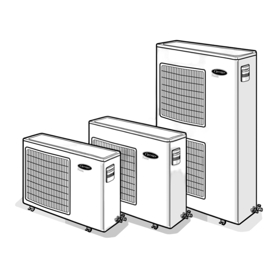
38GLP---G / 38GLP---G9 Dimensions and weight Mod. 38GLP 18 - 24 Mod. 38GLP 28 - 36 Mod. 38GLP 48 - 60 38GLP Mod. 1264 1264 Table II: Connections Connessioni Model 30 m 40 m 40 m 50 m 50 m 50 m Max. -
Page 4: Minimum Clearances
38GLP---G / 38GLP---G9 Minimum clearances E N G L I S H Mod. System charge Suitable up to Extra charge Extra charge (g) with indoor unit Nameplate Size 42VMC 40SMC 1200 – – Single-phase 1525 – 1265 – – 1265 2100 –... -
Page 5: General Information
38GLP---G / 38GLP---G9 General information Unit installation • All of the manufacturing and packaging materials used for your new appliance are compatible with the environment and can be recycled. R-410A systems operate at higher pressures than standard R-22 systems. • Dispose of the packaging material in accordance with local Do not use R-22 service equipment or components on R-410A requirements. -
Page 6: Warnings: Avoid
38GLP---G / 38GLP---G9 Warnings: avoid..E N G L I S H Disconnecting the refrigerant connections after installation: Excessive height difference between indoor and outdoor unit (see this will cause refrigerant leaks. Table II "Connections"). Excessive distance between indoor and Connecting the condensate drain pipe to the outdoor unit. -
Page 7: Refrigerant Connections
38GLP---G / 38GLP---G9 Refrigerant connections No moisture. No dust. Charge liquid-no gas. No leak. No mineral oil. Copper tubes during storage. Neat. 1/2” UNF (R-410A) Use tools designed for R-410A higher pressure. Keep inside clean. Dry nitrogen brazing. Min. – 100 kPa (–... - Page 8 38GLP---G / 38GLP---G9 Refrigerant connections E N G L I S H Flaring the ends of the tubing The unit can be installed: on the floor; on the wall using the bracket kit. Remove protective caps from copper tube ends.
-
Page 9: Operating Limits
38GLP---G / 38GLP---G9 Refrigerant connections Three-way valve Gas line (large diameter) Needle valve Liquid line (small diameter) Valve cap Flare nut Valve needle Indoor unit Two-way valve Outdoor unit Allen (hex. head) wrench Vacuum pump Air purging Use only a vacuum pump to purge air from the piping. -
Page 10: Electrical Connections
38GLP---G / 38GLP---G9 Electrical connections E N G L I S H Single-phase version Cooling only unit Cooling only system Terminal box legend, all models Connecting cable, indoor-outdoor units Earth (field wiring). Live power supply. Mains supply connecting cable L1 Live power supply. -
Page 11: Electrical Data
38GLP---G / 38GLP---G9 Electrical connections • For 230 V ~ 1 pH 50 Hz single-phase unit Before proceeding with the unit connection to the mains supply locate live L and neutral N, then make connections as shown in the wiring diagram. -
Page 12: Pump Down And Check The Refrigerant Charge
38GLP---G / 38GLP---G9 Pump Down and check the refrigerant charge E N G L I S H Pump-down Check the refrigerant charge Pump-down is an operation intended to collect all the system • This check becomes necessary after any refrigerant leak due to refrigerant in the outdoor unit. -
Page 13: Unit Maintenance
Istruzioni d’installazione supplementari 38GLP---G / 38GLP---G9 Unit maintenance, troubleshooting and guide for the owner Indoor unit coil • Condenser coil (outdoor or indoor, in case of heat pump operation) obstructed; remove obstructions. The following maintenance operations must be carried out by •... -
Page 14: Installation Instructions Supplement
38GLP---G Installation instructions supplement 38GLP---G9 E N G L I S H Cooling only Outdoor unit Indoor unit Head pressure controller (HPC) Loss of refrigerant pressure switch (LRPS) Pressure service port High pressure cut-out (HIP) Fan motor 38GLP...G units are designed to work in North European countries Features climates. - Page 15 38GLP---G Installation instructions supplement 38GLP---G9 Head pressure controller: wiring diagram 10FM - Fan Capacitor 1OFM - Fan motor Troubleshooting See paragraph “Troubleshooting”. Note: At start-up or in case of re-start after a stop of several hours at – 10°C, with low voltage supply (198V), high pressure switch HIP may trip off the unit.
- Page 16 L010126H11 - 0603 Via R. Sanzio, 9 - 20058 Villasanta (MI) Italy - Tel. 039/3636.1 The manufacturer reserves the right to change any product specifications without notice. June 2003 Printed in Italy...