Carrier 40GXC Service Manual
Hide thumbs
Also See for 40GXC:
- Product data (15 pages) ,
- Owner's manual (13 pages) ,
- Installation instructions manual (12 pages)
Table of Contents
Advertisement
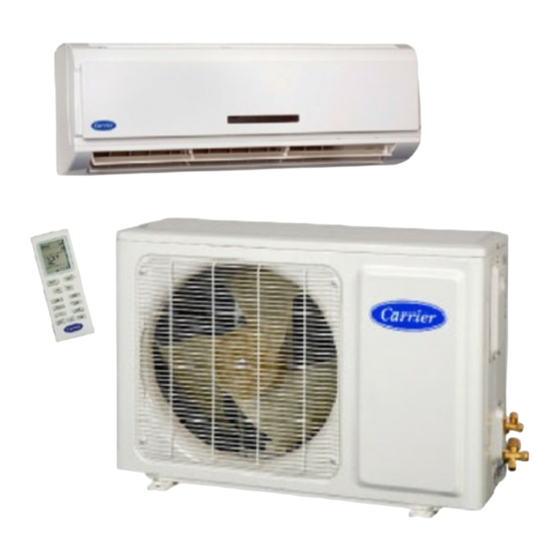
40GXC / 38GXC Cooling Only
40GXQ / 38GXQ Heat Pump
Inverter---Driven High Wall Duct---Free Split System
Sizes 009 to 012
INTRODUCTION
This Service Manual provides the necessary information to service,
repair, and maintain the 38/40GXC(Q).
TABLE OF CONTENTS
. . . . . . . . . . . . . . . . . . . . . . . . . . . . . . . . . . .
. . . . . . . . . . . . . . . . . . . . . . . . . . . . . . . . . . . . . .
. . . . . . . . . . . . . . . . . . . . . . . . . . . . . . . . . . . . .
. . . . . . . . . . . . . . . . . . . . . . . . . . . . . . . .
. . . . . . . . . . . . . . . . . . . . . . . . . . . . . . . . . . . . . . . . . . .
WIRING DIAGRAMS
. . . . . . . . . . . . . . . . . . . . . . . . . . . . . .
. . . . . . . . . . . . . . . . . . . . . . . . . . . . .
. . . . . . . . . . . . . . . . . . . . . . . . . . . .
. . . . . . . . . . . . . . . . . . . . . . . . .
. . . . . . . . . . . . . . . . . . . . . . . . . . . . . .
. . . . . . . . . . . . . . . . . . . . . . . . . . . . .
. . . . . . . . . . . . . . . . . . . . . . . . . . . . . . . . . . . .
Service Manual
PAGE
. . . . . . . . . . . . . . . . . . . . . . . . .
. . . . . . . . .
. . . . . . . . . . .
. . . . . . . . . . . . . . . . . . . .
. . . . . . . . . . . . . . . . . . . . . . . . . .
. . . . . . . . . . . . . . . . .
. . . . . . . . . . . . .
12- -13
. . . . . . . . . . . . . . . . . . . . . . . .
13- -15
24- -27
SAFETY CONSIDERATIONS
Improper installation, adjustment, alteration, service, maintenance,
or use can cause explosion, fire, electrical shock, or other
conditions which may cause death, personal injury, or property
damage. Consult a qualified installer, service agency, or your
distributor or branch for information or assistance. The qualified
installer or agency must use factory- -authorized kits or accessories
when modifying this product. Refer to the individual instructions
packaged with the kits or accessories when installing.
Follow all safety codes. Wear safety glasses, protective clothing,
1
and work gloves. Use quenching cloth for brazing operations.
2
Have fire extinguisher available. Read these instructions
3
thoroughly and follow all warnings or cautions included in
literature and attached to the unit. Consult local building codes and
4
National Electrical Code (NEC) for special requirements.
5
Recognize safety information. This is the safety- -alert symbol
6
When you see this symbol on the unit and in instructions or
7
manuals, be alert to the potential for personal injury.
7
Understand these signal words: DANGER, WARNING, and
CAUTION. These words are used with the safety- -alert symbol.
7
DANGER identifies the most serious hazards which will result in
7
severe personal injury or death.
8- -9
which could result in personal injury or death. CAUTION is used
to identify unsafe practices which may result in minor personal
10
injury or product and property damage. NOTE is used to highlight
11
suggestions which will result in enhanced installation, reliability, or
11
operation.
!
13
ELECTRICAL SHOCK HAZARD
16
Failure to follow this warning could result in personal injury
or death.
23
Before installing, modifying, or servicing system, main
electrical disconnect switch must be in the OFF position.
There may be more than 1 disconnect switch. Lock out and
tag switch with a suitable warning label.
WARNING signifies hazards
WARNING
! !
Advertisement
Table of Contents

Related Manuals for Carrier 40GXC


Summary of Contents for Carrier 40GXC
-
Page 1: Table Of Contents
40GXC / 38GXC Cooling Only 40GXQ / 38GXQ Heat Pump Inverter---Driven High Wall Duct---Free Split System Sizes 009 to 012 Service Manual INTRODUCTION SAFETY CONSIDERATIONS Improper installation, adjustment, alteration, service, maintenance, This Service Manual provides the necessary information to service, or use can cause explosion, fire, electrical shock, or other repair, and maintain the 38/40GXC(Q). -
Page 2: Model / Serial Number Nomenclature
MODEL NUMBER NOMENCLATURE INDOOR UNIT 1--- 01 Voltage Fan Coil Unit 1 --- 115 ---1 ---60 Nominal Capacity Unit Type 009 --- 3/4 Ton GXQ --- Heat Pump 012 --- 1 Ton GXC --- Cooling Only OUTDOOR UNIT 1--- 01 Air ---Cooled Condenser Voltage 1--- 115 ---1 ---60... -
Page 3: Standard Features And Accessories
STANDARD FEATURES AND ACCESSORIES INDOOR UNITS Ease Of Installation Mounting Brackets Low Voltage Controls Comfort Features Microprocessor Controls Wireless Remote Control Rapid Cooling/Heating Automatic Air Sweep Cold Blow Prevention Continuous Fan * Auto Restart Feature Memory Function Auto Changeover Energy Saving Features Inverter Driven Compressor A07892 Fig. -
Page 4: Specifications
PRODUCT SPECIFICATIONS System Model Number 53GXC009--- --- --- 1 53GXC012--- --- --- 1 53GXQ009--- --- --- 1 53GXQ012--- --- --- 1 System Voltage 115 V 115 V 115 V 115 V Control Voltage 0 --- 24v DC 0 --- 24v DC 0 --- 24v DC 0 --- 24v DC Capacity (Btuh) Clg/Htg... -
Page 5: Dimensions
DIMENSIONS - - INDOOR A08289 Net Operating Weight Unit Size In. (mm) In. (mm) In. (mm) Lbs. (Kg) 30.3 (770) 9.8 (250) 7.84 (1.99) 18.7 (8.5) 32.7 (830) 11.2 (285) 8.9 (225) 24.2 (11) Fig. 2 – Dimensions of Indoor Unit DIMENSIONS - - OUTDOOR A08290 Net Operating Weight... -
Page 6: Clearances
CLEARANCES - - INDOOR CEILING 6" (0.15m) min. 5" 5" (0.13m) (0.13m) min. min. (1.8m) FLOOR A07891 Fig. 4 – Indoor unit clearance CLEARANCES - - OUTDOOR Air-inlet Air-outlet A07894 UNIT 12k in. (mm) 20 (508) 20 (508) 24 (610) 12 (305) 12 (305) Fig. -
Page 7: System Operating Envelope
38/40GXQ SYSTEM OPERATING ENVELOPE Outdoor Temperature (_C) --- 40 --- 35 --- 30 --- 25 --- 20 --- 15 --- 10 --- 5 95_F Cooling Continuous 80_F Operation Heating Continuous Operation 60_F 55_F 115_F 55_F 14_F 75_F --- 10 Outdoor Temperature (_F) NOTE: Low ambient controls cannot be used with these systems A09247 Fig. -
Page 11: Refrigerant Lines
SYSTEM EVACUATION AND REFRIGERANT LINES CHARGING Routing – Refrigerant lines can be routed in any of the four directions shown in Fig. 10. CAUTION As viewed from front UNIT DAMAGE HAZARD 3 Left Exit Failure to follow this caution may result in equipment 1 Right Exit damage or improper operation. -
Page 12: Control System
SYSTEM SAFETIES Safety CODE POSSIBLE CAUSE 3 Minute Time Delay Freeze Protection, Indoor Coil Low Refrigerant Charge, Blocked Indoor Air Flow, or Dirty Air Filter High Compressor Discharge Temperature Low Refrigerant Charge, or Blocked Capillary Low Voltage Protection Low Voltage High Condensing Temperature High Ambient Temperature, or Loss of Condenser Airflow Compressor Over Current Protection... -
Page 13: Sequence Of Operation
MODES OF OPERATION Compressor Over Current Protection Over current protection can result due to any of the following: The units have five main operating modes: The ambient temperature is too high 1. Fan only 2. Cooling Locked rotor on the compressor 3. -
Page 14: Heating Mode
Heating Mode Cold Blow Prevention This function prevents the cold air from blowing into a space when In this mode, the system heats the room air with the indoor fan in heat mode. When there is a demand for heating one of the running at either the selected speed or on Auto. -
Page 15: Auto Mode
AUTO MODE SLEEP MODE When the Auto setting is selected, at startup the unit will run in Additional energy savings can be realized by selecting the Sleep cooling, fan only, or heating based on the room temperature at mode. When the sleep setting is selected, the temperature set point shown below. -
Page 16: Troubleshooting
TROUBLESHOOTING This section provides the required flow charts to troubleshoot problems that may arise. NOTE: Information required in the diagnoses can be found either on the wiring diagrams or in the appendix. Required Tools: The following tools are needed when diagnosing the units: S Digital multimeter S Screw drivers (Phillips and straight head) S Needle- -nose pliers... -
Page 17: Diagnostic Charts
DIAGNOSTIC CHARTS Indoor fan motor Indoor fan motor Indoor fan motor Check motor Check motor Check motor running? running? running? Chart Chart Chart Connect low side gauge at Connect low side gauge at Connect low side gauge at Check for leaks. Check for leaks. - Page 18 DIAGNOSTIC CHARTS (CONT.) Reset circuit breaker. Is Reset circuit breaker. Is Problem fixed Problem fixed Notes: Notes: problem fixed? problem fixed? Before measuring the Volts DC on outdoor TB, Before measuring the Volts DC on outdoor TB, disconnect the field wire on terminal S. disconnect the field wire on terminal S.
- Page 19 DIAGNOSTIC CHARTS (CONT.) Is unit running in outdoor Is unit running in outdoor Beyond operating range Beyond operating range ambient higher than ambient higher than 110 °F? 110 °F? Clean coil. Clean coil. Problem solved Problem solved Outdoor coil clean? Outdoor coil clean? Problem persists? Problem persists?
- Page 20 DIAGNOSTIC CHARTS (CONT.) Check heat sink for Check heat sink for Clean. Clean. obstruction and dirt obstruction and dirt Problem fixed? Problem fixed? Check if connection Check if connection See note below * See note below * is loose is loose Is problem fixed? Is problem fixed? Check voltage and current.
- Page 21 DIAGNOSTIC CHARTS (CONT.) Clean coil. Problem Clean coil. Problem Outdoor coil clean? Outdoor coil clean? Problem solved Problem solved persists? persists? Clean filter. Problem Clean filter. Problem Indoor filter clean? Indoor filter clean? Problem solved Problem solved persists? persists? Check indoor fan Check indoor fan Replace indoor fan Replace indoor fan...
- Page 22 DIAGNOSTIC CHARTS (CONT.) Visually confirm that fan Visually confirm that fan blades and outdoor coil blades and outdoor coil Clear blockage Clear blockage are not blocked. are not blocked. Trace connections from Trace connections from Fix connection Fix connection OD board. Connections OD board.
-
Page 23: Diagnostic Charts
DIAGNOSTIC CHARTS (CONT.) Check wiring and Check wiring and Fix wiring or Fix wiring or connection between connection between connection connection receiver and ID board. Ok? receiver and ID board. Ok? Check input and output Check input and output Replace receiver board Replace receiver board on ID and receiver on ID and receiver... -
Page 24: Appendix
APPENDIX APPENDIX TABLE OF CONTENTS DESCRIPTION NUMBER ..............Control Board Input or Output Values . - Page 25 A1 - - CONTROL BOARDS INPUT OR OUTPUT VALUES INDOOR BOARD CONNECTOR VOLTAGE INPUT DATA1 BLACK(24v max) relative to N DC INPUT BLUE (neutral) INPUT AC L1: BROWN(115v) relative to N AC [Pin1 BLACK (0--- 115v) Pin2:GREEN(0--- 115v) Pin3:YELLOW(0--- 115v) Pin5:BROWN(0--- 115v) OUTPUT FAN1: Pin6:RED(0--- 115v)] relative to Pin4:WHITE...
- Page 27 A3 - - CHARACTERISTICS OF TEMPERATURE SENSORS Indoor Outdoor Temperature ° F (° C) Return Air Coil Coil OD Air Comp. Discharge 10 (--- 12.2) 92220 123000 123000 92220 306200 50 (10.0) 29900 39870 39870 29900 98000 90 (32.2) 11090 14790 14790 11090...
- Page 28 Catalog No.38---40GX ---3SM Copyright 2011 Carrier Corp. S 7310 W. Morris St. S Indianapolis, IN 46231 Printed in U.S.A. Edition Date: 05/11 Replaces: 38--- 40GX--- 2SM Manufacturer reserves the right to change, at any time, specifications and designs without notice and without obligations.