Table of Contents
Advertisement
Quick Links
Advertisement
Table of Contents

Related Manuals for Bosch DS484Q


Summary of Contents for Bosch DS484Q
- Page 1 DS484Q/DS486Q Installation Instructions Quad Beam Photoelectric Detectors...
- Page 2 1.0 Overview Description The DS484Q and DS486Q are photoelectric quad beam detectors that use four pulsed infrared beams to activate an alarm relay upon detection of an intruder. Both models contain a transmitter that emits an invisible infrared beam, and a receiver. If the beam is broken, the receiver signals an alarm. Multiple channel operation provides increased system flexibility by allowing multiple devices to be used near each other without cross-talk or other interference.
- Page 3 1.3.5 Selectable Beams The beams in the DS484Q and DS486Q are configurable into eight different combinations (two groups by four channels). These combinations can eliminate false alarms that can occur from cross-talk when multiple beams are stacked, or when the transmitter and receiver are separated by a long distance.
- Page 4 1.3.6 Selectable AND/OR Gate Table 1: EDC BYPASS Switch States The photoelectric intrusion detection system in the DS484Q and DS486Q provides alarm relay activation Detector Status BYPASS Switch BYPASS Switch for different considerations. Use the DIP Switches to select the required protection:...
-
Page 5: Installation
• Do not disassemble or modify the base. Figure 5: Beam Spread 1 - Beam spread 3 - Horizontal spread 2 - Distance between transmitter and receiver 4 - Total vertical spread Bosch Security Systems, Inc. | 7/05 | 4998138530F... - Page 6 DS484Q/DS486Q | Installation Instructions | 2.0 Installation Mounting Figure 7: Using U-clamps Mount the DS484Q and DS486Q in one of two ways: • Pole mounted • Wall mounted 2.2.1 Pole Mounting 1. Choose an appropriate mounting location for the system. Install poles with a clear line-of- sight between the transmitter and the receiver.
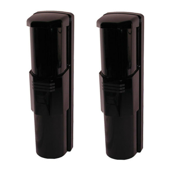
- Page 7 Wall Mounting 1 - Chassis 5 - Terminal block 2 - Base 6 - Wire entrance 3 - Cover 7 - Base mounting screws 4 - Mounting holes 8 - Cover mounting screw Bosch Security Systems, Inc. | 7/05 | 4998138530F...
- Page 8 1 - Power (non-polarized), 10.5 VDC to 28.0 VDC 2 - Alarm Output (1c), 30 VDC 0.2 A 3 - EDC Output (1b), 30 VDC 0.2 A 4 - Tamper Output (1b), 30 VDC 0.1 A Bosch Security Systems, Inc. | 7/05 | 4998138530F...
- Page 9 Figure 13: Two Sets on the Run – Wiring Example 1 - Terminal block on transmitter and receiver 4 - Power output 2 - Receiver 5 - Alarm input (INC) 3 - Transmitter Bosch Security Systems, Inc. | 7/05 | 4998138530F...
-
Page 10: Setup And Alignment
100 ms beam must be broken to cause an alarm. interruption time. Table 4: Beam Interruption Time Examples Interrupt Time (ms) Catch Performance Running Jogging Fast Walking Normal Walking Slow Moving Bosch Security Systems, Inc. | 7/05 | 4998138530F... - Page 11 110 to 120 180 to 200 set to Channel M. Set the remaining sets to Channel 1, (361 to 394) (591 to 656) 2, or 3. Bosch Security Systems, Inc. | 7/05 | 4998138530F...
- Page 12 Table 8 for the DIP Switches 1, 2, and 3, and the example for Group B, Channel 2 in Figure 18. When the POWER LED flashes, shut off the power and reconnect the wires correctly. Bosch Security Systems, Inc. | 7/05 | 4998138530F...
- Page 13 Difficult to do in a noisy Select a procedure based on the conditions and environment considerations of the specific installation. Refer to Table 9. Figure 19: Alignment Interruption Sheet Bosch Security Systems, Inc. | 7/05 | 4998138530F...
- Page 14 8. Do Steps 3 through 6 for the optical modules on the (Figure 21). receiver to align the transmitter image. Bosch Security Systems, Inc. | 7/05 | 4998138530F...
- Page 15 If outdoors, the alignment is complete when all LEDs are off. • If indoors, the alignment is complete when the lower two LEDs are off. 5. Repeat the procedure for the other optical module pair. Bosch Security Systems, Inc. | 7/05 | 4998138530F...
-
Page 16: Walk Test
Figure 24: Walk Test Pattern 1 - Receiver 3 - Beam path 2 - Transmitter 4 - Crossing the beam path Inspect the system and perform a walk test at least once a year. Bosch Security Systems, Inc. | 7/05 | 4998138530F... -
Page 17: Stacking Information
3 - Synchronized wiring Each top line set must be set to Channel M, and the other line sets to Channels 1, 2, or 3 to avoid incorrect communication between the stacking sets. Bosch Security Systems, Inc. | 7/05 | 4998138530F... -
Page 18: Troubleshooting
Frost or dew is present. Attach the optical heater. POWER LED on transmitter Synchro wires are not connected. Connect the synchro wiring correctly. Refer to flickers Section 4.1.4 Synchronized Wiring on page 12. Bosch Security Systems, Inc. | 7/05 | 4998138530F... -
Page 19: Specifications
4 hours (120 mAh) minimum required for UL Certificated Installations Temper Output Normally-closed contacts rated at 0.1 A @ 30 VDC Trigger Response Time Selectable response time of 35 ms to 700 ms Bosch Security Systems, Inc. | 7/05 | 4998138530F... - Page 20 Bosch Security Systems, Inc. 130 Perinton Parkway Fairport, NY 14450-9199 Customer Service: (800) 289-0096 Technical Support: (888) 886-6189 © 2005 Bosch Security Systems 4998138530F...